Language selection

Search

Patent 2186837 Summary

Third-party information liability

Some of the information on this Web page has been provided by external sources. The Government of Canada is not responsible for the accuracy, reliability or currency of the information supplied by external sources. Users wishing to rely upon this information should consult directly with the source of the information. Content provided by external sources is not subject to official languages, privacy and accessibility requirements.

Claims and Abstract availability

Any discrepancies in the text and image of the Claims and Abstract are due to differing posting times. Text of the Claims and Abstract are posted:

  • At the time the application is open to public inspection;
  • At the time of issue of the patent (grant).
(12) Patent Application: (11) CA 2186837
(54) English Title: PROCESS AND PLANT FOR THE PRODUCTION OF A GAS UNDER PRESSURE BY CRYOGENIC DISTILLATION
(54) French Title: PROCEDE ET INSTALLATION CRYOGENIQUE DE PRODUCTION DE GAZ SOUS PRESSION
Status: Deemed Abandoned and Beyond the Period of Reinstatement - Pending Response to Notice of Disregarded Communication
Bibliographic Data
(51) International Patent Classification (IPC):
  • F25J 03/02 (2006.01)
  • F25J 03/04 (2006.01)
(72) Inventors :
  • DE L'ISLE, MIKE (France)
  • KOEBERLE, YVES (France)
(73) Owners :
  • L'AIR LIQUIDE, SOCIETE ANONYME POUR L'ETUDE ET L'EXPLOITATION DES PROCEDES GEORGES CLAUDE
(71) Applicants :
  • L'AIR LIQUIDE, SOCIETE ANONYME POUR L'ETUDE ET L'EXPLOITATION DES PROCEDES GEORGES CLAUDE (France)
(74) Agent: NORTON ROSE FULBRIGHT CANADA LLP/S.E.N.C.R.L., S.R.L.
(74) Associate agent:
(45) Issued:
(22) Filed Date: 1996-09-30
(41) Open to Public Inspection: 1997-03-30
Availability of licence: N/A
Dedicated to the Public: N/A
(25) Language of filing: English

Patent Cooperation Treaty (PCT): No

(30) Application Priority Data:
Application No. Country/Territory Date
95 11 474 (France) 1995-09-29

Abstracts

English Abstract


In a process for the production of gas under
pressure by cryogenic distillation, the gas is produced
by vaporizing (or pseudo-vaporizing) a liquid drawn off
from a distillation column. In order to supply addi-
tional gas under pressure, a flow of a gas coming from
an external source is at least partially liquefied, and
the liquid thus formed is added to the liquid drawn off
from the column before or after an optional or
pressurization step.


Claims

Note: Claims are shown in the official language in which they were submitted.

- 5 -
The embodiments of the invention in which an exclusive
property or privilege is claimed are defined as follows:
1. Process for the production of a gas under pres-
sure in a cryogenic separation apparatus, comprising
the steps of:
i) cooling a fluid to be separated in a heat
exchanger (9) and sending it to a distillation column
(12) of the apparatus;
ii) drawing off a liquid flow from a column
(14) of the apparatus and heating it in the exchanger
(9),
characterized in that
iii) at least one make-up liquid is added to
the liquid flow drawn off in step ii);
iv) the mixture thus formed by the make-up
liquid and the flow drawn off is heated and optionally
vaporized by indirect heat exchange in an exchanger
(9); and
v) a gas under pressure is recovered at the
outlet of the apparatus.
2. Process according to Claim 1, characterized in
that make-up gas coming from an external source (19) is
sent to an exchanger, the make-up gas is cooled and it
is at least partially condensed to form the make-up
liquid.
3. Process according to Claim 1 or 2, in which the
make-up liquid and the flow drawn off have substan-
tially the same composition.
4. Process according to one of Claims 1 to 3, in
which the liquid drawn off is a liquid enriched in
oxygen, nitrogen, argon or methane.
5. Process according to one of the preceding
claims, in which most of the gas under pressure comes
from a distillation column (14).
6. Process according to Claim 5, in which at least
80% of the gas under pressure comes from a column of
the apparatus.
7. Process according to one of Claims 1 to 6, in
which the make-up liquid is added to the drawn-off flow
upstream or downstream of a pressurization means (25).

- 6 -
8. Process according to one of the preceding
claims, in which the fluid to be separated condenses at
least partially in the exchanger (9) in which the
liquid drawn off in step (ii) vaporizes.
9. Process according to one of the preceding
claims dependent on Claim 2, in which the make-up gas
is cooled in the exchanger (9) in which the liquid
drawn off in step (ii) vaporizes.
10. Process according to one of the preceding
claims, in which no final product in liquid form is
produced.
11. Plant for the production of a gas flow under
pressure by cryogenic distillation, comprising at least
one distillation column (13, 14), a heat exchanger (9),
means (1A, 1B, 1C) for sending a fluid to be separated
by distillation to a distillation column (13, 14),
means (31) for drawing off a liquid from a distillation
column (14), and means for sending the drawn-off liquid
to the heat exchanger (9) in order to heat the liquid,
characterized in that it comprises:
- means (27) for adding a make-up liquid to the
drawn-off liquid upstream of the exchanger and means
for sending the mixture thus formed to the exchanger
(9) in order to form the gas under pressure.
12. Plant according to Claim 11, comprising means
(20) for sending a make-up gas coming from an external
source to the exchanger (9) in order to cool the make-
up gas, and means (21, 23) for liquefying the at least
partially cooled make-up gas in order to form the make-
up liquid.
13. Plant according to Claim 11 or 12, in which the
liquid drawn off is a liquid enriched in oxygen, nitro-
gen or argon.
14. Plant according to Claim 11, 12 or 13, in which
the means for drawing off a liquid are connected to the
low-pressure column (14) of a double air-distillation
column (12).
15. Plant according to one of Claims 11 to 14, in
which the means for sending the drawn-off liquid to the

- 7 -
exchanger are connected to a pressurization means (25)
upstream of the exchanger.
16. Plant according to Claim 15, in which the means
for adding a liquefied make-up gas to the drawn-off
liquid are connected to the means for sending the
drawn-off liquid to the exchanger downstream or
upstream of the pressurization means (25).
17. Plant according to one of Claims 11 to 16, in
which the means (1A, 1B, 1C) for sending the fluid to
be separated to a column pass at least partially
through the exchanger (9).

Description

Note: Descriptions are shown in the official language in which they were submitted.


The present invention relates to a process and
to a plant for the production of gas under pressure by
cryogenic distillation. In particular, it relates to a
process in which gas under pressure is produced by
vaporizing a liquid drawn off from a cryogenic distil-
lation column.
Processes of this type are well-known in the
art and have existed for several decades.
In the present document, the pressures referred
to are absolute pressures. Furthermore, the terms
"condensation" and "vaporization" are intended to mean
either condensation or vaporization proper, or pseudo-
condensation or pseudo-vaporization, depending on
whether the pressures are subcritical or supercritical.
The object of the invention is to make it pos-
sible to supply the maximum demand for gas under pres-
sure with an apparatus designed to produce only a part
of the liquid required for supplying the maximum gas
demand.
According to the invention, a process is pro-
vided for the production of a gas under pressure in a
cryogenic separation apparatus, comprising the steps
of:
i) cooling a fluid to be separated in a heat
exchanger and sending it to a distillation column of
the apparatus for separation therein;
ii) drawing off a liquid flow from a column of
the apparatus and heating it in the exchanger,
characterized in that
iii) at least one make-up liquid is added to
the liquid flow drawn off in step ii);
iv) the mixture thus formed by the make-up
liquid and the flow drawn off is heated by indirect
heat exchange in an exchanger; and
v) a gas under pressure is recovered at the
outlet of the apparatus.
In this way, a gas coming from an external
source is used to make up for the lack of liquid when
the apparatus is operating at its maximum capacity.
,, A. . ~

- 21 86837
-- 2
The liquefied make-up gas may have the same
composition as the liquid flow drawn off.
The liquid may be an atmospheric gas. For
example, liquid nitrogen may be drawn off from the head
of a single column or of a low-pressure or medium-
pressure column of a double column. Liquid argon may be
obtained at the head of an argon column. However, the
invention also applies to the separation of other
cryogenic fluids; the liquid to be vaporized could be
methane, carbon monoxide or hydrogen, for example.
Before it is vaporized, the liquid may be pres-
surized either by hydrostatic pressure or using a pump.
If the make-up gas is already at the vaporiza-
tion pressure of the liquid drawn off, after it has
been liquefied, it may be added to the drawn-off liquid
downstream of the pressurization means. Otherwise, the
liquefied make-up gas is mixed with the liquid upstream
of the pump, before being pressurized therein.
The liquefied make-up gas preferably consti-
tutes 20% of the vaporized liquid flow, thus allowingthe apparatus to be designed for a capacity which rep-
resents 80~ of maximum demand.
According to the invention, :a plant is also
provided for the production of a gas flow under
pressure by cryogenic distillation, comprising at least
one distillation column, a heat exchanger, means for
sending a fluid to be separated by distillation to a
distillation column, means for drawing off a liquid
fro~ a distillation column, and means for sending the
drawn-off liquid to the heat exchanger in order to heat
the liquid, characterized in that it comprises means
for adding a make-up liquid to the drawn-off liquid
upstream of the exchanger and means for sending the
mixture thus formed to the exchanger in order to
vaporize it and form the gas under pressure.
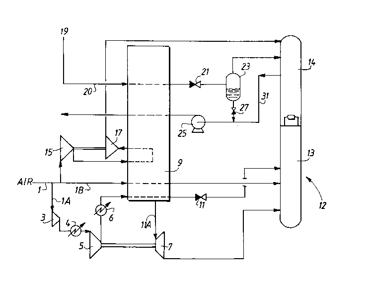
An illustrative embodiment of the invention is
shown in Figure 1, which schematically represents a
plant according to the invention.

21 86837
- 3
An airflow 1 is compressed to 5.6 x 10⁵ kPa in a
compressor, before being divided into three fractions.
The first fraction lA is compressed to 62 x 105 kPa by
the compressor 3, refrigerated at 4 and compressed to
76 x 105 kPa. After a second refrigeration step at 6,
the fraction lA is cooled in a main exchanger 9. A part
of the partially cooled air llA is drawn off at an
intermediate temperature level from the exchanger 9 and
pressure-relieved, to the pressure of a medium-pressure
column 13 of a double column 12, in a turbine 7. The
pressure-relieved air is then sent into this column 13.
The remaining part of the flow lA continues to be
cooled in the exchanger 9, condenses and is pressure-
relieved, to the pressure of the column 13, in the
lS valve 11 before being sent into this column.
The fraction lB passes through the exchanger 9
before being introduced at the bottom of the column 13.
The fraction lC is compressed to 8.9 x 10⁵ kPa
by the compressor 15, partially cooled in the exchanger
9 and pressure-relieved, to the pressure of the low-
pressure column 14, by the injection turbine 17. The
pressure-relieved fraction lC is sent to the column 14,
optionally after a supercooling step. The injection
turbine 17 drives the compressor 15.
The double column 12, comprising the low-pres-
sure column 14 and the medium-pressure column 13, is
designed to produce an average liquid flow which
vaporizes in the exchanger 9 to form a gas under pres-
sure. In the example, the liquid is oxygen drawn off at
a pressure of about 1.5 x 10⁵ kPa from the bottom of the
column 14 via the conduit 31. The liquid is pressurized
to 76 x 105 kPa by a pump 25, before being vaporized in
the exchanger 9 to form oxygen under pressure.
Make-up oxygen gas comes from a network 19 at
30 x 105 kPa. The make-up gas from the conduit 20 cools
in the exchanger 9, is pressure-relieved through the
valve 21 and is separated into two phases in the
separator 23. The gaseous part of the oxygen is sent at
least in part to the low-pressure column 14. The liquid
... .. .. .. ..... .. . . . . ~ .

2l86837
;
_ - 4
part is sent to the conduit 31 when the oxygen demand
exceeds the maximum capacity of the double column 12,
which represents 80~ of the maximum demand. The liquid
coming from the network is thus vaporized to form up to
20~ of the maximum demand. This percentage is limited
by the capacity for liquefying the oxygen from the net-
work acceptable to the exchanger 9.
In this way, a down-sized apparatus can never-
theless be used to supply the entire demand for oxygen
gas under pressure, with lower energy costs.

Representative Drawing
A single figure which represents the drawing illustrating the invention.
Administrative Status

2024-08-01:As part of the Next Generation Patents (NGP) transition, the Canadian Patents Database (CPD) now contains a more detailed Event History, which replicates the Event Log of our new back-office solution.

Please note that "Inactive:" events refers to events no longer in use in our new back-office solution.

For a clearer understanding of the status of the application/patent presented on this page, the site Disclaimer , as well as the definitions for Patent , Event History , Maintenance Fee  and Payment History  should be consulted.

Event History

Description Date
Inactive: IPC from MCD 2006-03-12
Time Limit for Reversal Expired 2003-09-30
Application Not Reinstated by Deadline 2003-09-30
Deemed Abandoned - Failure to Respond to Maintenance Fee Notice 2002-09-30
Application Published (Open to Public Inspection) 1997-03-30

Abandonment History

Abandonment Date Reason Reinstatement Date
2002-09-30

Maintenance Fee

The last payment was received on 2001-08-23

Note : If the full payment has not been received on or before the date indicated, a further fee may be required which may be one of the following

  • the reinstatement fee;
  • the late payment fee; or
  • additional fee to reverse deemed expiry.

Patent fees are adjusted on the 1st of January every year. The amounts above are the current amounts if received by December 31 of the current year.
Please refer to the CIPO Patent Fees web page to see all current fee amounts.

Fee History

Fee Type Anniversary Year Due Date Paid Date
MF (application, 2nd anniv.) - standard 02 1998-09-30 1998-08-18
MF (application, 3rd anniv.) - standard 03 1999-09-30 1999-09-01
MF (application, 4th anniv.) - standard 04 2000-10-02 2000-09-01
MF (application, 5th anniv.) - standard 05 2001-10-01 2001-08-23
Owners on Record

Note: Records showing the ownership history in alphabetical order.

Current Owners on Record
L'AIR LIQUIDE, SOCIETE ANONYME POUR L'ETUDE ET L'EXPLOITATION DES PROCEDES GEORGES CLAUDE
Past Owners on Record
MIKE DE L'ISLE
YVES KOEBERLE
Past Owners that do not appear in the "Owners on Record" listing will appear in other documentation within the application.
Documents

To view selected files, please enter reCAPTCHA code :


To view images, click a link in the Document Description column. To download the documents, select one or more checkboxes in the first column and then click the "Download Selected in PDF format (Zip Archive)" or the "Download Selected as Single PDF" button.

List of published and non-published patent-specific documents on the CPD .

If you have any difficulty accessing content, you can call the Client Service Centre at 1-866-997-1936 or send them an e-mail at CIPO Client Service Centre.


Document
Description 
Date
(yyyy-mm-dd) 
Number of pages   Size of Image (KB) 
Representative drawing 1998-03-29 1 13
Abstract 1997-02-02 1 13
Description 1997-02-02 4 161
Claims 1997-02-02 3 101
Drawings 1997-02-02 1 18
Reminder of maintenance fee due 1998-06-01 1 111
Courtesy - Abandonment Letter (Maintenance Fee) 2002-10-27 1 179
Reminder - Request for Examination 2003-06-01 1 113
Courtesy - Office Letter 1996-10-30 1 31