Language selection

Search

Patent 2186903 Summary

Third-party information liability

Some of the information on this Web page has been provided by external sources. The Government of Canada is not responsible for the accuracy, reliability or currency of the information supplied by external sources. Users wishing to rely upon this information should consult directly with the source of the information. Content provided by external sources is not subject to official languages, privacy and accessibility requirements.

Claims and Abstract availability

Any discrepancies in the text and image of the Claims and Abstract are due to differing posting times. Text of the Claims and Abstract are posted:

  • At the time the application is open to public inspection;
  • At the time of issue of the patent (grant).
(12) Patent Application: (11) CA 2186903
(54) English Title: PIPE REPAIR OR JOINTING COLLAR
(54) French Title: COLLIER POUR LE RACCORD OU LA REPARATION DE CANALISATIONS
Status: Deemed Abandoned and Beyond the Period of Reinstatement - Pending Response to Notice of Disregarded Communication
Bibliographic Data
(51) International Patent Classification (IPC):
  • F16L 55/17 (2006.01)
  • F16L 17/04 (2006.01)
  • F16L 19/07 (2006.01)
  • F16L 21/06 (2006.01)
  • F16L 55/172 (2006.01)
(72) Inventors :
  • HODGE, IAN STUART (United Kingdom)
  • MADSEN, JENS SONDERBY (Denmark)
(73) Owners :
  • AVK MANUFACTURING LIMITED
(71) Applicants :
  • AVK MANUFACTURING LIMITED (United Kingdom)
(74) Agent: BORDEN LADNER GERVAIS LLP
(74) Associate agent:
(45) Issued:
(22) Filed Date: 1996-09-30
(41) Open to Public Inspection: 1997-09-06
Availability of licence: N/A
Dedicated to the Public: N/A
(25) Language of filing: English

Patent Cooperation Treaty (PCT): No

(30) Application Priority Data:
Application No. Country/Territory Date
9604697.4 (United Kingdom) 1996-03-05

Abstracts

English Abstract


- 12 -
A pipe repair or jointing collar, comprising a pair or
arcuate segments (10) with clamping means (at 11) for drawing the
segments together along an axis (XX) to form a collar around a pipe
or a plurality of pipe ends, each segment (10) having an associated
sealing member comprising a pair of longitudinally-spaced arcuate
sealing strips (21) between the respective ends of which extend a pair
of longitudinal sealing strips (20) with wedge-like members (18)
embedded therein adapted to progress generally inwardly each towards
the axis (XX) with respect to the segments (10) as the latter are
drawn together in order to force the sealing members (20, 21) radially
inwards locally of the wedge-like members (18). The integral
formation of the sealing members and wedge-like members provide a
minimum number of parts to aid assembly of the collar in hazardous
conditions.


French Abstract

- 12 - Collier servant à réparer ou à joindre des tuyaux comprenant une paire de segments en forme d'arc (10) muni d'un moyen de serrage (à 11) pour tirer les segments l'un vers l'autre sur un axe (XX) pour former un collier autour d'un tuyau ou d'un certain nombre d'extrémités de tuyaux, chaque segment (10) ayant un élément de scellement associé comprenant une paire de bandes de scellement en forme d'arc espacées longitudinalement (21) entre les extrémités respectives desquelles s'étend une paire de bandes de scellement longitudinales (20) dotées d'éléments en forme de coin (18) noyés dans ces dernières conçus de manière à bouger généralement vers l'intérieur en direction de l'axe (XX) par rapport aux segments (10) au moment où ces derniers sont tirés l'un vers l'autre pour forcer les éléments de scellement (20, 21) radialement vers l'intérieur et les approcher des éléments en forme de coin (18). La configuration intégrale des éléments de scellement et des éléments en forme de coin donne un nombre minimum de pièces, ce qui facilite l'assemblage du collier dans des conditions dangereuses.

Claims

Note: Claims are shown in the official language in which they were submitted.

- 9 -
THE EMBODIMENTS OF THE INVENTION IN WHICH AN EXCLUSIVE
PROPERTY OR PRIVILEGE IS CLAIMED ARE DEFINED AS FOLLOWS:
1. A pipe repair or jointing collar comprising a plurality of
arcuate segments with clamping means for drawing the segments
together to form the collar around a pipe or around a plurality of
pipe ends, with interposition of corresponding deformable sealing
means, each arcuate segment having an associated sealing member,
each sealing member comprising a pair of longitudinally spaced
arcuate sealing strips between the respective ends of which extend a
pair of longitudinal sealing strips, rigid wedge-like members being
provided within the segments in the regions of the clamping means
and adapted to progress generally inwardly with respect to the
segments as the latter are drawn together thus to force the sealing
members radially inwards in said regions; characterised in that the
wedge-like members are non-removably formed with the sealing
members.
2. A pipe repair or jointing collar according to Claim 1,
wherein the wedge-like members are embedded within the longitudinal
sealing strips which are integrally formed with the arcuate sealing
strips thus to form a one-piece sealing means of rectangular form
when laid flat.
3. A pipe repair or jointing collar according to Claim 1 or
Claim 2, wherein the longitudinal sealing strips include at their
respective ends a pair of integral lugs each having means for
engagement with a part of a respective arcuate segment.

- 10 -
4. A pipe repair or jointing collar according to Claim 1,
comprising a pair of said arcuate segments and a pair of said sealing
means each associated with one of the segments, the longitudinal
sealing strips of the pair of sealing means having mutually abutting
flat faces, the arcuate sealing strips extending to lie co-planar with
said flat faces.
5. A pipe repair or jointing collar according to Claim 2,
wherein there is provided at each corner defined by a respective
arcuate sealing strip and a longitudinal sealing strip a generally
triangular strengthening web integrally formed with the arcuate and
longitudinal sealing strips.
6. A pipe repair or jointing collar according to Claim 1,
wherein the arcuate sealing strips are curved about an axis transverse
to the longitudinal sealing strips.
7. A pipe repair or jointing collar according to Claim 1,
wherein the wedge-like members are of cast iron.
8. A pipe repair or jointing collar according to Claim 1,
wherein the wedge-like members are of aluminium.
9. A pipe repair or jointing collar according to Claim 1,
wherein each sealing member comprising the arcuate sealing strips and
the longitudinal sealing strips, is formed as one piece integrally of
natural or synthetic rubber.

- 11 -
10. A pipe repair or jointing collar, according to Claim 1,
wherein each arcuate sealing strip has a smooth inner sealing surface.
11. A pipe repair or jointing collar according to Claim 1,
wherein each longitudinal sealing strip is surrounded by slightly
inclined surfaces extending inwardly from the outer edges thereof.
12. A pipe repair or jointing collar according to Claim 1,
wherein the shape of each longitudinal sealing strip, and the material
thereof is selected such that the longitudinal sealing strips themselves
serve as wedge-like members.

Description

Note: Descriptions are shown in the official language in which they were submitted.


2 18~9~
- 1 - PE/2439
A PIPE REPAIR OR IOINTING COLLAR
THIS INVENTION concerns split collars for repairing and
jointing pipes such as gas pipes and water pipes. Such collars may
serve to repair a single damaged pipe, to form a joint between two
aligned pipe ends, or to serve as a tee piece to join one pipe with
another or others extending at an angle therefrom.
Repair or jointing collars for this purpose take many
different forms. Usually they must be designed to correspond very
closely with the outer diameter of the pipes thus to ensure a
watertight or gas tight seal. Since the collars are designed to be
fitted to existing underground mains some of which can be many
years old, it is very difficult to ensure that it will always provide an
adequate seal. Owing to changing standards, materials, manufacturing
techniques and corrosion, pipes of the same nominal diameter can
vary widely in actual diameter. Therefore, it is desired that such a
collar should be able to accommodate wide variations and differences
in pipe diameter.
One known form of repair collar designed for this
purpose comprises a pair of arcuate segments whose abutting end
faces are inclined with respect to a diammetral plane of the collar so
that as the segments are drawn together the respective inclined faces
undergo relative sliding movement thus squee~ing the pipe at a
plurality of positions around its circumferences. This requires
sufficient resilience or flexibility in the material from which the

;~ 1 8~9Q3
-
- 2 - PE/2439
segments are made so that they may be deformed inwardly to define
a smaller radius. However since this kind of arrangement does not
ensure a uniform reduction throughout the circumference, certain
zones remain in which adequate sealing cannot be assured.
A further known form of repair collar designed to
overcome the aforementioned difficulty is described and claimed in
patent specification GB 2189000 in which there is provided a collar
comprising a pair of arcuate segments with clamping means for
drawing the segments together around the pipe, with interposition of
one or more corresponding elastomeric arcuate sealing means, and
characterised by wedge-like members located between the segments
and the sealing means in the region of the clamping means so that
the wedge-like members are adapted to slide generally inwardly with
respect to the segments as the latter are drawn together thus to
force the sealing means radially inwards in those regions.
One disadvantage experienced in the use of collars of
this latter kind is that accurate assembly of the segrnen~s~ the sealing
means and the wedge-like members, sometimes presents practical
difficulties, particularly since such collars must be assembled on site
and sometimes in a very hostile environment. Thus, accuracy of
assembly cannot always be guaranteed, and the integrity of a seal
provided by the collar is heavily reliant upon accurate assembly and
tightening of the separate parts of the collar.
The present invention seeks to avoid these difficulties at

~186903
- 3 - PE/2439
least to a considerable extent.
According to the present invention a pipe repair or
jointing collar comprises a plurality of arcuate segments with
clamping means for drawing the segments together to form the collar
around a pipe or around a plurality of pipe ends, with interposition of
corresponding deformable sealing means, each arcuate segment having
an associated sealing member, each sealing member comprising a pair
of longitudinally spaced arcuate sealing strips between the respective
ends of which extend a pair of longitudinal sealing strips, rigid wedge-
like members being provided within the segments in the regions of the
clamping means and adapted to progress generally inwardly with
respect to the segments as the latter are drawn together thus to
force the sealing members radially inwards in said regions;
characterised in that the wedge-like members are non-removably
formed with the sealing members.
Preferably, the wedge-like members are embedded within
the longitudinal sealing strips which are integrally formed with the
arcuate sealing strips thus to form a one-piece sealing means of
rectangular form when laid flat.
Still further, the longitudinal sealing strips include at
their respect ends a pair of integral lugs each having means for
engagement with a part of a respective arcuate segment whereby
each sealing means may be pre-assembled with its respective arcuate
segment prior to assembly of the collar.

2186903
- 4 - PE/2439
In one embodiment the collar comprises a pair of arcuate
segments and a pair of sealing means each associated with one of the
segments, the longitudinal sealing strips of the pair of sealing means
having mutually abutting flat faces, the arcuate sealing strips
extending to lie co-planar with said flat faces.
Also in a preferred embodiment there is provided at each
corner defined by a respective arcuate sealing strip and longitudinal
sealing strip a generally triangular strengthening web integrally formed
with the arcuate and longitudinal sealing strips.
It is further preferred that the inner arcuate faces of
the arcuate sealing strips are curved about an axis transverse to the
longitudinal sealing strips.
An embodiment of the invention will now be described
with reference to the accompanying drawings, in which:-
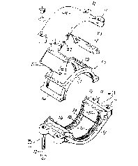
Fig. 1 illustrates a pipe repair or jointing collar of thekind previously described in GB 2189000;
Fig. 2 is a vertical cross-section through a pipe repair or
jointing collar made in accordance with the invention, as if taken
along line 11-11 of Fig. 1.
and Fig. 3 is an exploded view of a pair of sealing means
being part of the collar illustrated in Fig. 2.

~ 1 8f~9~3
- 5 - PE/2439
Referring now to Fig. 1, the collar illustrated therein
includes a pair of generally semi-cylindrical segments 10 of cast iron
or a similar rigid material. Each segment 10 has at each end thereof
a pair of radially directed bolt-receiving lugs 11 for drawing the
segments together by means of bolts 12.
Each segment 10 receives an elastomeric sealing member
generally indicated at 13 and consisting of circumferentially ribbed
sealing strips 14 and longitudinally ribbed sealing strips 15 and 16.
Each strip 16 serves to join adjacent ends of the circumferential
strips 14 whilst each strip 15 also extends between the latter but at
a circumferential position spaced from their ends. Adjacent each pair
of radial lugs l l and disposed between the body of the segment in
this region and the ad jacent part of the sealing member 13 is a
separate sliding wedge-like member 17. As can be seen from the
lower part of Fig. 1, each wedge 13 is retained in position on its
associated segment 10 by means of the arcuate sealing strips 14 and
the longitudinal sealing strips 15 and 16 with the strips located in
respective channels in the wedge.
Internally protruding ribs 18 integral with the segments
10 serve to prevent longitudinal movement of the sealing members 13
and wedges 17.
Each wedge 17 slidingly abuts a generally tangential inner
face of the associated segment 10. By this means, as the segments
are drawn together by bolts 12, after initial contact of the ad jacent

~ ~186903
- 6 - PE/2439
faces of the respective sealing strips, further closure of the segments
10 will cause the wedges 17 to slide generally inwardly with a
component of circumferential movement with respect to the adjacent
segment surfaces thus to force the sealing members radially inwards
in the regions of the radial lugs 11. Thus, there is substantially
uniform reduction in the diameter of the sealing strips around the
circumference of the pipe to ensure a good seal thereon substantially
without deformation of the segment~ thpm~elves.
For example, on a nominal 1 50mm diameter pipe the
range of actual diameters which may be accommodated whilst
providing an effective seal is at least 20mm.
Referring now to Fig. 2 and in accordance with the
present invention, wedge-like inserts 18 of cast iron or aluminium are
embedded within and thus formed integrally with the longitudinal
sealing strips 20 which are themselves formed integrally with arcuate
sealing strips 21 in such a manner that the inner sealing surfaces of
the arcuate sealing strips 21 extend upwardly to a flat surface 22 co-
planar with a flat surface 23 exten-ling along each longitudinal sealing
strip 20.
It can be seen from Fig. 2 that as the segments 10 are
drawn together along the axis XX then the wedge-like inserts 18
embedded within the longitudinal sealing strips 20 will tend to move
along the adjacent tangential surfaces of the segments, in each case
towards the XX axis thereby forcing the arcuate sealing strips

2 1 ~69~3
- 7 - PE/2439
inwardly along an axis YY in the region of the radial lugs 11, i.e.
where the clamping action on the segments is applied. This inwardly
directed sealing effect ensures a uniform circumferential seal without
deforming the segments themselves.
Referring now to Fig. 3 each sealing member can be
seen in greater detail as consisting of the longitudinal sealing strips
20 and the arcuate sealing strips 21. The entire sealing member is
integrally formed from a resilient material such as natural or
synthetic rubber and, when each member is laid flat it is of
rectangular form having, at each corner a triangular strengthening
web 24, again integrally formed with the arcuate and longitudinal
sealing strips.
Exten-ling OII~W~1 dly in a direction generally radially with
respect to the assembled collar is an integral lug 25 having an
aperture 26 therein for engagement upon abutments such as are
illustrated in Fig. 1 at 27 on the segments 10. Thus, each sealing
member may be pre-assembled with its respective segrne-nt~ no further
separate parts being required during final assembly when the two pre-
assembled segments with se~ling means thereon are brought together
and clamped by bolts 12.
Unlike the arcuate sealing strips 14 of Fig. 1, those
made in accordance with the invention and illustrated at 21 in Figs. 2
and 3 have smooth inner sealing surfaces which, however, are slightly
curved about their respective arcuate axes i.e. in the longitudinal
direction of the collar. Similarly, the flat surfaces 23 of the

2l8G9c33
- 8 - PE/2439
longitudinal sealing strips 20 which are co-planar with similar flat
faces 28 at the adjacent ends of the associated arcuate sealing strips
21, are surrounded by slightly inclined surfaces 29 extending inwardly
from the outer edges of each longitudinal strip 20.
By extending the arcuate sealing strips right up to the
sealing faces of the longitudinal strips integrity of the arcuate sealing
strips is ensured.
It is not intended to limit the invention to the details
described herein. For example, the embedded wedge-like inserts can
be omitted in certain applications wherein the shape of the
longitudinal sealing strips and the material thereof is selected such
that they serve as wedge-like members to achieve an adequate seal.

Representative Drawing
A single figure which represents the drawing illustrating the invention.
Administrative Status

2024-08-01:As part of the Next Generation Patents (NGP) transition, the Canadian Patents Database (CPD) now contains a more detailed Event History, which replicates the Event Log of our new back-office solution.

Please note that "Inactive:" events refers to events no longer in use in our new back-office solution.

For a clearer understanding of the status of the application/patent presented on this page, the site Disclaimer , as well as the definitions for Patent , Event History , Maintenance Fee  and Payment History  should be consulted.

Event History

Description Date
Inactive: IPC from MCD 2006-03-12
Application Not Reinstated by Deadline 2003-09-30
Time Limit for Reversal Expired 2003-09-30
Deemed Abandoned - Failure to Respond to Maintenance Fee Notice 2002-09-30
Inactive: Cover page published 2000-12-21
Application Published (Open to Public Inspection) 1997-09-06

Abandonment History

Abandonment Date Reason Reinstatement Date
2002-09-30

Maintenance Fee

The last payment was received on 2001-04-30

Note : If the full payment has not been received on or before the date indicated, a further fee may be required which may be one of the following

  • the reinstatement fee;
  • the late payment fee; or
  • additional fee to reverse deemed expiry.

Patent fees are adjusted on the 1st of January every year. The amounts above are the current amounts if received by December 31 of the current year.
Please refer to the CIPO Patent Fees web page to see all current fee amounts.

Fee History

Fee Type Anniversary Year Due Date Paid Date
Registration of a document 1996-09-30
MF (application, 2nd anniv.) - standard 02 1998-09-30 1998-09-29
MF (application, 3rd anniv.) - standard 03 1999-09-30 1999-04-21
MF (application, 4th anniv.) - standard 04 2000-10-02 2000-05-24
MF (application, 5th anniv.) - standard 05 2001-10-01 2001-04-30
Owners on Record

Note: Records showing the ownership history in alphabetical order.

Current Owners on Record
AVK MANUFACTURING LIMITED
Past Owners on Record
IAN STUART HODGE
JENS SONDERBY MADSEN
Past Owners that do not appear in the "Owners on Record" listing will appear in other documentation within the application.
Documents

To view selected files, please enter reCAPTCHA code :


To view images, click a link in the Document Description column. To download the documents, select one or more checkboxes in the first column and then click the "Download Selected in PDF format (Zip Archive)" or the "Download Selected as Single PDF" button.

List of published and non-published patent-specific documents on the CPD .

If you have any difficulty accessing content, you can call the Client Service Centre at 1-866-997-1936 or send them an e-mail at CIPO Client Service Centre.


Document
Description 
Date
(yyyy-mm-dd) 
Number of pages   Size of Image (KB) 
Representative drawing 1997-09-29 1 11
Representative drawing 2000-12-04 1 11
Abstract 1997-02-10 1 23
Description 1997-02-10 8 259
Claims 1997-02-10 3 81
Drawings 1997-02-10 3 69
Reminder of maintenance fee due 1998-06-01 1 111
Courtesy - Abandonment Letter (Maintenance Fee) 2002-10-27 1 179
Reminder - Request for Examination 2003-06-01 1 113
Prosecution correspondence 1996-11-04 1 16