Note: Descriptions are shown in the official language in which they were submitted.
- WO 95127323 2 1 8 7 1 1 9 pcr/sE95loo338
TITLE OF THE INVENTION: ELASTOMERIC CONNECTOR
Technical Field
The present invention relates ~o an elastically
deformable, elastomeric, electrical connector having
electrically conductive elements extending in parallel
between opposite ends of said connecror.
The invention also relates to a use of the
elastomeric connector for mounting and electrically
connecting a piece of radio communication equipment with an
electrical circuit.
~ackqround of the Invention
Radio communication apparatuses such as mobile tele-
phones always comprise at least one microphone unit and one
hearing capsule or speaker. The assembly of for example a
microphone requires the following de~ands to be fulfilled:
vibrations, scratches and noise entering the plastic cover
of for example a mobile telephone must be absorbed; speech
entering the cover from the speaker, which is mounted in
the same cover, needs to be absorbed in order to avoid echo
effects; an electrical connection has to be achieved
between the microphone and the PCB (Printed Circuit Board);
occurring TDMA ( Time Division Multiplexing Access) hum has
to be suppressed; high production flow and yield together
with favourable cost-efficiency shouid be accomplished.
Today the most common way to c^nnect a microphone is
to solder two wires between the microphone and the PCB
which carries the amplifier. Subsequently, the microphone
is placed in a rubber gasket which can absorb the distur-
bances mentioned above. However, soldering has the disad-
W095l27323 PCT/SE95~0338
21871lq
vantage of being difficult to au-omatize since in this case
soldering has to be made by hand. Consequently, the produ_-
tion rate is slowed down and undesired costs are taken.
There is also a certain risk for mixing the wires with each
other.
In order to facilitate the soldering, the wires must
be long enough. However, this may cause problems at the
final assembly, since there is a r_sk that a long wire may
be pressed between mechanical parts, such that the leads
are either cut off or shortened to an undesiràble signal,
e.g. ground.
Another metod to connect a microphone is to solder
one end of a piece of flex film to ~he microphone, where-
upon the other end thereof is soldered or pressed onto
connection pads on the PCB.
US-A-5 205 751 discloses an e;ectrically conductive,
elastomeric connector for electrica'iy connecting a portion
of a first substrate with a portior. of a second substrate,
said connector having a tubular shaped body with first and
second claw arms. No soldering is needed, since the
elastically deformable connector is ixed into position by
compressing it between the two subs._ates.
In order to suppress the TDMA hum, which is frequent-
ly occurring especially in GSM terminals, a capacitor has
to be soldered directly on the microphone. As a consequence
the microphone becomes more expensive and the sensitivity
thereof is decreased since it is heated during soldering.
US-A-5 200 717 discloses an apparatus for inter-
connecting and shielding active elec~rical circuitry,
wherein an electrically conductive elastomer material is
used instead of metal for the purpose of shielding and at
the same time has the advantage of being compressible.
It is obvious that none of the prior art is capable
of meeting all the requirements state~ above.
W095/27323 2 1 8 7 1 1 9 PCT/SE~SI~.33X
The Invention
The object of the present inven.ion is to provide a
method of shielding and electrically connecting a piece of
radio communication equipment with an electrical circuit.
According to the invention this object can be achieved by
means of the elastically deformable, electrically conduc-
tive, low-resistance, elastomeric connector having the
characterising eatures of claim 1. Preferred detail
embodiments of such elastomeric connector are defined in
claims 2-7.
Another object of the present invention is to accomp-
lish a method of absorbing vibrations and noise entering
the radio communication equipment.
A further object of the present invention is to
provide a method of mounting a microphone in radio commu-
nication equipment without needing to mount a capacitor
directly on the microphone in order to suppress TDMA hum.
Yet another object of the present invention is to
accomplish a method of assembling a piece of radio comm~ni-
cation equipment which permits high production flow and
yield at a low cost.
Still another ob~ect Or the present invention is to
accomplish a method of assembling which permits increased
miniaturization of radio communication equipment.
25 - In order to obtain the objects mentioned above it is
further suggested according to the invention, to use the
elastomeric connector in ways defined in claims 8-10.
The Drawinqs
Preferred embodiments of the invention will be
described in more detail beiow, reference being made to the
accompanying drawings, in which
Fig 1 is a perspective view of a first embodiment of
the elastomeric connector according to the invention,
W095~7323 2 1 8 7 1 1 9 PCT/SEgS/00338
Fig 2 is a perspective view of a second embodiment of
the elastomeric onnector according to the invention,
Fig 3 is a cross sectional view of a mounting of a
microphone with the elastomeric connector according to Fig
2,
Fig 4 is an end view of the mounting of an elasto-
meric connector with the microphone according to Fig 3,
Fig 5 is a cross sectional view of an alternative
mounting of the microphone by means of the elastomeric
connector according to Fig 2,
Fig 6 is an end view of the alternative mounting of
an elastomeric connector with the microphone according to
Fig 5,
Fig 7 is a cross sectional view of a second alterna-
tive mounting of the microphone by means of the elastomeric
connector according to Fig 2,
Fig 8 is an end view of the second alternative
mounting of an elastomeric connector with the microphone
according to Fig 7,
Fig 9 is a cross sectional view of a third embodiment
of the elastomeric connector according to the invention,
and
Fig 10 is a perspective view of a fourth embodiment
of the elastomeric connector according to the invention.
DescriPtion of Embodiments of the Invention
Fig 1 shows an elastically deformable, electrically
conductive, low-resistance elastomeric connector 10
comprising an elastomeric material filled with spaced apart
metal wires lla having high conductivity, preferably made
of gold or goldplated metal. A useful property of such
conductive elastomers is that they contain a plurality of
minute conductors that conduct linearly through the
material without conducting laterally within the material.
` V095/27323 2 1 8 7 1 1 9 PCT/SEg5/00338
The elastomeric connector may have any shape, e.g circular,
rectangular etc.
By shortcircuiting the respective ends of said con-
nector the conducting wires made of conducting material
together form conductors extending in parallel from a first
end of the connector to a second end thereof. If said ends
are shortcircuited by an annular member the wires together
form one conducting path. Normally, electrical units are
connected to electrical circuits and other units by two or
more paths. One path may provide a shielding of the second
path. Such a '~twin lead" connection can be achieved
according to the invention. If further paths are desired,
more annular members may be added.
Fig 2 shows a second embodiment according to the
invention of an elastically deformable, electrically
conductive, low-resistance, elastomeric connector 10 which
is constituted of alternating conducting layers or slices
llb and non-conducting intermediate slices, wherein all
slices preferably are made of silicon. According to this
embodiment two or more apertures 12 are stamped out of the
elastomeric connector 10. Said apertures are through holes
extending in parallel with said conducting slices llb. Both
apertures 12 interupt at least one common slice llb, there-
by forming an island of at least one cut off slice there-
between. The cut off slice is used as a first conductingpath 13 for connecting a first electric means to a first
conducting element or pad on a second electric means or a
circuit board. A second conducting path 14 is formed by
engaging the elastomeric connector 10 to a second substan-
3C tially annular conducting element enclosing or surroundingthe cut off slice.
Preferably said second conducting element is connec-
ted to ground, thereby forming a shield around the cut off
slice. The shield is effective in all directions even
w09s~7323 21 ~ 7 1 1 9 PCT/SE95/~
though no conducting layers exist in some planes parallel
to a line connecting said apertures or if the annular shape
of said second conductive element is partly interrupted.
Figs 3 and 4 show an example of the assembly of a
S piece of radio communication equipment such as a micr~phone
15, buzzer, hearing capsule etc in a mobile telephone,
wherein the microphone is arranged in a rubber gasket 6.
The elastomeric connector 10 having two apertures is provi-
ded between the rear side of the microphone and a sub-
strate, preferably in the form of a PCB 17, where it is
fixed into contact with one center connection pad and one
peripheral connection pad on the microphone and
correspondingly-on an electrical circuit of the PCB by
mechanically compressing the elastomer to an extent of
about 7-12 %. The center first conducting path 13 in this
case is constituted by five slices or cut off planes. All
other layers of the connector together form the second
conducting path 14 which constitutes a shield for the
center first conducting path 13.
One connection pad on the microphone and one on the
circuit board are both connected to said center first
conducting path 13. A second annular connection pad on the
microphone and one on the circuit board are both connected
to said second conducting path 14, said annular connection
pads forming a short circuit of the layers together forming
the second conducting path. ~he elastomeric connector 10 is
provided with the conducting layers l1b oriented in a
direction perpendicular to the PCB 17.
It is sometimes desirable that a microphone 15 or a
buzzer etc is mounted in a direction perpendicular to the
PCB 17, thus making the sound input from the bottom of the
telephone or the sound output from the top of the telephone
available, as illustrated in Figs 5 and 6. In such cases
the connection pads on the PCB are provided on an edge
s/27323 ~ ~ J 1 q 9 PCT/SE95/Oo~
portion 18 thereof. The elastomeric connector 10 is
arranged with its ~onducting layers llb oriented in a
direction perpendicular to the edge portion 18.
A further example of mounting a microphone 15 o~
buzzer perpendicular to a PCB 17 is shown in Figs 7 and 8.
In this case a spring contact 19 soldered to the PCB forms
an electrical connection between the PCB and the elasto-
meric connector 10, which is connected to the ~icrophone or
buzzer. The ground signal from the microphone or buzzer is
connected through the elastomer directly to connecting pads
on the PCB. In order to o~tain ground connection the con-
ducting layers of the elastomeric connector must be
oriented in such a way that the alternating layers of con-
ductive and non-conductive silicone are perpendicular to
the PCB.
A third embodiment of the elastomeric connector
according to the present invention s shown in Fig 9. In
this case an elastomeric connector 10 is manufacture~ by
moulding an electrically conductive elastomer, for example
silicon containing silver or copper pellets. A gasket 16 is
formed as an integral part of the elastomeric connector
which comprises a central cylinder, forming the first con-
ducting path 13 surrounded by a coaxial tube, forming the
second conducting path 14 with an insulator 20 provided in
a gap 21 between the two parts of electrically conducting
elastomer. This solution has several advantages in that the
elastomer provides an electrical conductor, a shield, a
holder for a microphone or buzzer as well as a gasket. As
an alternative (not shown herein) the gasket 16 can be
formed as a cylinder of non-conducting elastomeric
material, which receives the microphone therein, said
microphone then being connected to a PCB by means of an
electrically conductive elastomeric connector.
W095~73~ 2 1 87 1 1 9 P~ SI~C3~
As shown in Fig 9, the front end of the elastomeric
connector 10 may optionally be located on the outside of
the cover 22 of a radio communication apparatus. As a
result, when the apparatus is placed on an even surface,
the microphone sound input is completely plugged. This is a
common way to deal with the problem of acoustic instabili-
ty.
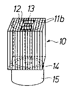
Fig 10 shows a fourth embodiment of the present
invention, wherein the elastomeric connector comprises an
elongated sheet 23 of elastomeric material having one or
more layers of spaced apart conducting metal wires lla. The
elongated sheet is then rolled up into a roll and may then
be connected to a microphone 15, thus forming first and
second conducting paths 13, 14.
The elastomeric connector according to the present
invention offers several advantages over the prior art
including: excellent absorption of vibration and speach;
good electrical contact; good shielding from radiated HF;
no capacitor needs to be soldered on the microphone;
improved compact design possible; high production flow and
yield; favourable economy.
While the present invention has been described in
connection with the preferred embodiments shown in the
figures, it will be apparent to those skilled in the art
that various other modifications and substitutions can be
made. Accordingly, it is understood that the present inven-
tion has been described by way of illustration and not
limitation.