Language selection

Search

Patent 2187238 Summary

Third-party information liability

Some of the information on this Web page has been provided by external sources. The Government of Canada is not responsible for the accuracy, reliability or currency of the information supplied by external sources. Users wishing to rely upon this information should consult directly with the source of the information. Content provided by external sources is not subject to official languages, privacy and accessibility requirements.

Claims and Abstract availability

Any discrepancies in the text and image of the Claims and Abstract are due to differing posting times. Text of the Claims and Abstract are posted:

  • At the time the application is open to public inspection;
  • At the time of issue of the patent (grant).
(12) Patent: (11) CA 2187238
(54) English Title: CURLING STABILIZER DEVICE
(54) French Title: DISPOSITIF DE STABILISATION POUR LE JEU DE CURLING
Status: Expired and beyond the Period of Reversal
Bibliographic Data
Abstracts

English Abstract


A curling stabilizer device for attachment to a curling brush handle has a framemember which includes a generally linear handle graspable by the hand of a curling
thrower and at least one structural member for spacing the handle from the curling brush
at a distance suitable for gripping by a sliding thrower. A releasable gripping device
encompasses the brush handle and fixedly attaches the frame member to the brush handle.
The frame member is oriented relative to the gripping device so that when the
gripping device is in gripping engagement with the brush handle, the linear handle
extends in line with the brush handle.


French Abstract

Dispositif stabilisateur de curling destiné à être fixé au manche d'un balai de curling, comprenant un bâti avec poignée généralement linéaire saisissable par la main d'un lanceur et au moins un élément de structure permettant d'espacer la poignée du balai à une distance appropriée pour la saisie par un lanceur glissant. Un dispositif de serrage entoure le manche du balai et attache l'élément de bâti au manche du balai. L'élément de bâti est orienté par rapport au dispositif de serrage de sorte que lorsque le dispositif de serrage est en contact étroit avec le manche du balai, la poignée linéaire se déploie en ligne avec le manche du balai.

Claims

Note: Claims are shown in the official language in which they were submitted.

THE EMBODIMENTS OF THE INVENTION IN WHICH AN EXCLUSIVE
PROPERTY OR PRIVILEGE IS CLAIMED ARE DEFINED AS FOLLOWS:
1. A curling stabilizer for stabilizing the delivery of a curling stone in the
game of
curling, comprising:
a supporting assembly including a longitudinal shaft for general alignment
with
the direction of delivery and a stabilizing member transversely attached
adjacent one end
of said longitudinal shaft, said stabilizing member and longitudinal shaft
having
ice-contacting surfaces for slideable movement over ice during delivery of the
curling stone
while providing lateral stabilization to said supporting assembly; and
an upright frame affixed to said supporting assembly, said frame including a
generally linear handle graspable by the hand of the player and at least one
structural
member for spacing said handle from the longitudinal shaft at a height
suitable for
gripping by the sliding player when in correct balance, said linear handle
being generally
oriented parallel to said longitudinal shaft.
2. The curling stabilizer as claimed in claim 1 wherein said shaft lies in
substantially
the same plane as said stabilizer member.
3. The curling stabilizer device as claimed in claim 1 or 2, wherein the
linear handle
is provided with a hand grip.
4. The curling stabilizer device as claimed in claim 3, wherein said hand grip
is a
rubberized sleeve.
5. The curling stabilizer device as claimed in any of claims 1 to 4, wherein
said
frame has a generally inverted U-shape.
6. The curling stabilizer device as claimed in any of claims 1 to 4, wherein
said
frame is generally L-shaped.
7. The curling stabilizer device as claimed in any of claims 1 to 4, wherein
said
longitudinal member is a curling brush handle, and said frame is attached to
said brush
handle by means of a sleeve slidable thereover the brush handle and including
locking
bolts for locking the sleeve to the handle.
-5-

8. The curling stabilizer device as claimed in any of claims 1 to 4, wherein
said
linear handle extends at a slight angle downwardly to the rear when said
longitudinal shaft
is in position on an ice surface to facilitate the delivery of a curling
stone.
9. The curling stabilizer device as claimed in claim 8, wherein said angle is
about
20°.
10. A curling stabilizer assembly comprising a curling brush having a
longitudinal
shaft and brush head, and a sub-assembly comprising a frame including a
generally linear
handle graspable by the hand of a curling thrower and at least one structural
member for
spacing said handle from the curling brush at a distance suitable for gripping
by the
thrower, and releasable gripping means encompassing said brush longitudinal
shaft and
fixedly attaching said frame member to said longitudinal shaft, said frame
being oriented
relative to said gripping means so that said linear handle extends in line
with said
longitudinal shaft and at right angles to said brush head.
11. The curling stabilizer assembly as claimed in claim 10, wherein the linear
handle
is provided with a hand grip.
12. The curling stabilizer assembly as claimed in claim 11, wherein said hand
grip is a
rubberized sleeve.
13. The curling stabilizer assembly as claimed in any of claims 10 to 12,
wherein said
frame has a generally inverted U-shape.
14. The curling stabilizer assembly as claimed in any of claims 10 to 12,
wherein said
frame is generally L-shaped.
15. The curling stabilizer assembly as claimed in any of claims 10 to 12,
wherein said
gripping means comprise a sleeve slidable over the brush handle including
locking bolts
for locking the sleeve to the handle.
16. The curling stabilizer assembly as claimed in any of claims 10 to 12,
wherein said
linear handle extends at a slight angle downwardly to the rear when said
longitudinal shaft
is in position on an ice surface to facilitate the delivery of a curling
stone.
17. The combination as claimed in claim 16, wherein said angle is about
20°.
-6-

18. The use of the curling stabilizer claimed in any one of claims 1 to 9 to
stabilize a
player during delivery of a curling stone in the game of curling.

Description

Note: Descriptions are shown in the official language in which they were submitted.


CA 02187238 1999-12-24
CURLING STABILIZER DEVICE
This invention relates to a stabilizer device for use in the game of curling.
The game of curling is played on a long sheet of ice having a set of
concentric
circles at each end, known as "the house". In play, a curling "rock", is
thrown from one
end of the sheet toward the house at the other end by the thrower whose task
is to impart
the rock with the exactly the right velocity vector to cause it come to rest
as close to the
center of the house as possible or to guard a rock in the house or to take out
a rock in the
house.
Members of the throwers team brush the ice ahead of the moving rock, thereby
reducing the friction between the rock and the ice to affect its distance and
direction of
travel.
Much of the skill resides in imparting exactly the right velocity vector to
the rock.
For this purpose, the thrower must carefully line himself up with the desired
direction of
travel, make a sliding motion along the ice, and at exactly the right moment,
release the
rock so that continues along the desired trajectory.
' During the sliding phase, and in particular immediately prior to the
release, it is
vital that the thrower remain in an absolutely stable balanced sliding
position. If the
thrower is off balance, at the moment of release, he will not be travelling
along the
desired trajectory and the rock will be sent off course.
Each curler has a brush for polishing the ice, and it is common practice for
thrower to use the brush in some fashion as a stabilizing device, and indeed
this is the
normal method that is taught by professionals.
The two most common methods for using the brush as a stabilizing device are as
follows:
a) T'he thrower holds the brush with the non-throwing arm and to one side at
an
angle with the brush head facing upward on the ice and the handle rising
upwardly and the top end tucked under the arm and slightly behind the back.
-1-

CA 02187238 2000-04-17
b) The thrower holds the brush with the non-throwing arm flat on the ice with
the
brush headl facing upward and pointing forward on the ice and the handle
parallel to the body and at the side.
With the first method, the brush often does not offer enough stability during
the
slide because it can't be leaned on heavily in this position or the slide will
break down.
With the second method, ,the curler often must position himself too low to the
ice during
the slide, thereby losing the "touch or feel" that comes from releasing from a
higher
position.
An object of t:he invention is to alleviate these problems.
According to the present invention there is provided a curling stabilizer for
stabilizing the delivery of a curling stone in the game of curling, comprising
a supporting
assembly including a longitudinal shaft for alignment with the direction of
delivery and a
stabilizing member transversely attached adjacent one end of said longitudinal
shaft, said
stabilizing member and longitudinal shaft having ice-contacting surfaces for
slideable
movement over ice during delivery of the curling stone while providing lateral
stabilization to said supporting assembly; and an upright frame affixed to
said supporting
assembly, said frame including a generally linear handle graspable by the hand
of the
player and at least one structural member for spacing said handle from the
longitudinal
shaft at a height suitable for gripping by the sliding player when in correct
balance, said
linear handle being generally oriented parallel to said longitudinal shaft.
The frame member can have any suitable shape. For example, it can be generally
U-shaped or L-shaped. The linear handle preferably inclines downwardly toward
the rear.
Using the device according to the invention, a thrower is able to stabilize
himself
during the sliding motion without leaning over and while maintaining the axis
of the
device in line with his motion vector.
Conveniently.. the linear handle is provided with a rubber or plastic grip.
The invention will now be described in more detail, by way of example, only
with
reference to the accompanying drawings, in which:
-2-

CA 02187238 1999-12-24
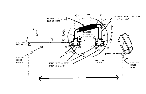
Figure 1 is a perspective view of a curling brush fitted with a stabilizer
device in
accordance with a first embodiment of the invention; and
Figure 2 is a view similar to Figure 1 of curling brush fitted with a
stabilizer
device in accordance with a second embodiment of the invention.
Refernng to Figure 1, a conventional curling brush 1 has a linear brush handle
2,
of either 3/4 or 1" in diameter, and a brush head 3.
A frame 4, which is generally of inverted U-shape, has vertical limbs 5 and a
cross
member 6, which is generally inclined at a slight angle of about 20°
downwardly toward
the distal end 8 of the brush handle 2.
The cross-member 6 defines a linear handle which is covered by a sleeve 7 of
rubberized material that forms a comfortable grip for the hand of the thrower.
The frame 4 is made of substantially rigid plastic pipe that can be bent into
shape
by the application of heat and pressure. Typically the pipe is '/z or 3/4"
diameter and 24"
long, the front limb 5 being 8" high, the cross member 6 being 12" long, and
the rear limb
5 being 4" high.
The free ends of the limbs 5 terminate in the socket portion 11 of plastic T
joints
9, which include a transverse sleeve 10 snugly fitting slidably onto the brush
handle 2.
The sleeves 10 have a pair of threaded bores 12 receiving bolts 13. With the
aid of
bolts 13, the sleeves 10 can be firmly clamped to the brush handle 2.
As will be seen in Figure l, the handle 7, although slightly inclined, lies in
a plane
containing the brush handle 2, which is generally at right angles to the brush
head 3.
To use the device, the thrower first slides the sleeves 10 onto the brush
handle 2
down to the desired position, whereupon the bolts 13 are tightened to clamp
the sleeves
firmly to the brush handle 2 with the frame 4 lying in the vertical plane when
the brush
head 3 lies flat on the ice.
During a throw, the thrower can now lay the brush flat on the ice with the
brush
handle 2 lined up along the desired direction of travel. As the thrower slides
forward. he
or she maintains a grip on the sleeve 7, which is also now lined up with the
direction of
-3-

CA 02187238 1999-12-24
travel. The frame is sufficiently rigid to allow the thrower to use the device
as a support to
maintain the correct balance as he or she slides along the ice.
During brushing operations the device can be removed, or if desired left in
place.
Figure 2 shows a slightly different embodiment where the frame is L-shaped.
Otherwise the principle is the same as the first embodiment. The thrower fits
the single
sleeve 10 onto the brush handle 2 and clamps it into place with bolts 13. The
plastic pipe
has sufficient inherent rigidity to balance the-thrower without the need for
the second
limb.
It is important that the handle 7 be clamped substantially in line with the
brush
handle 2 and in a plane perpendicular to the plane containing the brush head 3
so that
when the latter is laid flat on the ice, the frame will extend up vertically
to present the
handle 7 to the thrower. However, many different gripping devices, such as
clamps and
the like, can be employed to attach the frame 4 to the brush handle 2, as will
be apparent
to one skilled in the art.
Also many different shapes of frame can be employed so long as a generally
linear
handle is provided which is lined up with the axis of the brush handle and
arranged at a
height suitable for gripping by a sliding thrower when in correct balance.
-4-

Representative Drawing
A single figure which represents the drawing illustrating the invention.
Administrative Status

2024-08-01:As part of the Next Generation Patents (NGP) transition, the Canadian Patents Database (CPD) now contains a more detailed Event History, which replicates the Event Log of our new back-office solution.

Please note that "Inactive:" events refers to events no longer in use in our new back-office solution.

For a clearer understanding of the status of the application/patent presented on this page, the site Disclaimer , as well as the definitions for Patent , Event History , Maintenance Fee  and Payment History  should be consulted.

Event History

Description Date
Time Limit for Reversal Expired 2016-10-07
Letter Sent 2015-10-07
Inactive: IPC deactivated 2015-03-14
Inactive: IPC from PCS 2015-01-17
Inactive: IPC expired 2015-01-01
Inactive: IPC removed 2014-11-04
Maintenance Request Received 2014-09-03
Maintenance Request Received 2013-09-13
Inactive: Office letter 2002-09-10
Revocation of Agent Requirements Determined Compliant 2002-09-10
Grant by Issuance 2000-12-26
Inactive: Cover page published 2000-12-25
Pre-grant 2000-09-07
Inactive: Final fee received 2000-09-07
Letter Sent 2000-08-24
Notice of Allowance is Issued 2000-08-24
Inactive: Approved for allowance (AFA) 2000-07-05
Amendment Received - Voluntary Amendment 2000-04-17
Inactive: Office letter 2000-01-31
Inactive: S.30(2) Rules - Examiner requisition 2000-01-31
Inactive: Adhoc Request Documented 2000-01-31
Amendment Received - Voluntary Amendment 1999-12-24
Inactive: S.30(2) Rules - Examiner requisition 1999-12-09
Inactive: Status info is complete as of Log entry date 1999-11-17
Letter sent 1999-11-17
Advanced Examination Determined Compliant - paragraph 84(1)(a) of the Patent Rules 1999-11-17
Inactive: Application prosecuted on TS as of Log entry date 1999-11-17
All Requirements for Examination Determined Compliant 1999-10-14
Request for Examination Requirements Determined Compliant 1999-10-14
Inactive: Advanced examination (SO) fee processed 1999-10-14
Inactive: Cover page published 1999-09-30
Application Published (Open to Public Inspection) 1998-04-07
Small Entity Declaration Determined Compliant 1996-10-07

Abandonment History

There is no abandonment history.

Maintenance Fee

The last payment was received on 2000-10-10

Note : If the full payment has not been received on or before the date indicated, a further fee may be required which may be one of the following

  • the reinstatement fee;
  • the late payment fee; or
  • additional fee to reverse deemed expiry.

Please refer to the CIPO Patent Fees web page to see all current fee amounts.

Fee History

Fee Type Anniversary Year Due Date Paid Date
MF (application, 2nd anniv.) - small 02 1998-10-07 1998-10-07
MF (application, 3rd anniv.) - small 03 1999-10-07 1999-09-22
Request for examination - small 1999-10-14
Advanced Examination 1999-10-14
Final fee - small 2000-09-07
MF (application, 4th anniv.) - small 04 2000-10-10 2000-10-10
MF (patent, 5th anniv.) - small 2001-10-08 2001-09-20
MF (patent, 6th anniv.) - small 2002-10-07 2002-09-09
MF (patent, 7th anniv.) - small 2003-10-07 2003-08-01
MF (patent, 8th anniv.) - small 2004-10-07 2004-07-12
MF (patent, 9th anniv.) - small 2005-10-07 2005-08-11
MF (patent, 10th anniv.) - small 2006-10-10 2006-09-28
MF (patent, 11th anniv.) - small 2007-10-08 2007-09-12
MF (patent, 12th anniv.) - small 2008-10-07 2008-09-18
MF (patent, 13th anniv.) - small 2009-10-07 2009-08-13
MF (patent, 14th anniv.) - small 2010-10-07 2010-09-08
MF (patent, 15th anniv.) - small 2011-10-07 2011-09-19
MF (patent, 16th anniv.) - small 2012-10-09 2012-08-07
MF (patent, 17th anniv.) - small 2013-10-07 2013-09-13
MF (patent, 18th anniv.) - small 2014-10-07 2014-09-03
Owners on Record

Note: Records showing the ownership history in alphabetical order.

Current Owners on Record
EARLE MORRIS
Past Owners on Record
None
Past Owners that do not appear in the "Owners on Record" listing will appear in other documentation within the application.
Documents

To view selected files, please enter reCAPTCHA code :


To view images, click a link in the Document Description column. To download the documents, select one or more checkboxes in the first column and then click the "Download Selected in PDF format (Zip Archive)" or the "Download Selected as Single PDF" button.

List of published and non-published patent-specific documents on the CPD .

If you have any difficulty accessing content, you can call the Client Service Centre at 1-866-997-1936 or send them an e-mail at CIPO Client Service Centre.


Document
Description 
Date
(yyyy-mm-dd) 
Number of pages   Size of Image (KB) 
Cover Page 1999-09-30 1 46
Drawings 1999-11-18 2 43
Description 1999-12-24 4 169
Claims 1999-12-24 2 83
Claims 2000-04-17 3 95
Description 2000-04-17 4 168
Cover Page 2000-12-06 1 47
Abstract 1997-02-18 1 17
Cover Page 1997-02-18 1 15
Description 1997-02-18 4 171
Claims 1997-02-18 2 77
Drawings 1997-02-18 2 47
Cover Page 1998-04-15 1 46
Representative drawing 2000-12-06 1 11
Representative drawing 1998-04-15 1 10
Reminder of maintenance fee due 1998-06-09 1 111
Commissioner's Notice - Application Found Allowable 2000-08-24 1 163
Notice: Maintenance Fee Reminder 2003-07-08 1 115
Notice: Maintenance Fee Reminder 2004-07-08 1 119
Notice: Maintenance Fee Reminder 2005-07-11 1 117
Notice: Maintenance Fee Reminder 2006-07-10 1 118
Notice: Maintenance Fee Reminder 2007-07-10 1 121
Notice: Maintenance Fee Reminder 2008-07-08 1 122
Notice: Maintenance Fee Reminder 2009-07-08 1 118
Notice: Maintenance Fee Reminder 2010-07-08 1 122
Notice: Maintenance Fee Reminder 2011-07-11 1 122
Notice: Maintenance Fee Reminder 2012-07-10 1 128
Notice: Maintenance Fee Reminder 2013-07-09 1 120
Notice: Maintenance Fee Reminder 2014-07-08 1 119
Notice: Maintenance Fee Reminder 2015-07-08 1 127
Maintenance Fee Notice 2015-11-18 1 170
Second Notice: Maintenance Fee Reminder 2016-04-11 1 118
Fees 2003-08-01 1 68
Correspondence 1996-11-04 4 105
Correspondence 2000-09-07 1 29
Fees 2002-09-09 1 92
Correspondence 2002-09-10 1 11
Correspondence 2002-09-10 1 14
Correspondence 2002-09-09 1 24
Fees 2000-10-10 1 28
Fees 2004-07-12 1 41
Fees 2005-08-11 1 45
Fees 2006-09-28 1 43
Fees 2007-09-12 1 47
Fees 2008-09-18 1 42
Fees 2009-08-13 1 53
Fees 2010-09-08 1 48
Fees 2011-09-19 1 93
Fees 2012-08-07 1 22
Fees 2013-09-13 1 155
Fees 2014-09-03 1 127