Note: Descriptions are shown in the official language in which they were submitted.
21 ~ 7243
DIESEL ENGINE EXHAUST PARTICLE COLLECTION DEVICE
BACKGROUND OF THE INVENTION
1. Field of the Invention
The present invention relates to an electrically
controlled diesel engine exhaust particle collection device.
2. Description of the Prior Art
As is well known, the exhaust of diesel engines
contains large quantities of carbon particles (so-called
black smoke); these carbon particles are discharged into the
atmosphere through the exhaust passage and, after blowing
about in the air for a long time, finally settle in the form
of soot on to floors, road surfaces and clothing etc.
However, it has gradually become clear that, since carbon
possesses strong adsorption for other substances, various
chemical substances such as carcinogen-related substances
are adsorbed on to the carbon particles whilst they are free
in the air, and that the entry of these into the human body
when such carbon particles are breathed in by people causes
cancer or diseases of the respiratory system. The diesel
engines used in vehicles such as trucks and buses therefore
1
....
21 ~ 7243
now represent a considerable social problem as a source of
environmental air pollution.
Accordingly, in order to protect the environmental air
from contamination by diesel black smoke, as set out in
Japanese Utility Model Application Kokai Sho.61-55114 and
Japanese Utility Model Application Kokai Sho.61-84851, a
black smoke collection device has been proposed wherein a
black smoke removal filter consisting of metallic fibres
and/or a honeycomb-shaped element or the like is arranged in
the exhaust passage of a diesel engine mounted on a vehicle.
However, such black smoke removal filters have the drawbacks
that, when used for a long time, they get clogged up by the
black smoke which they collect and pressure loss is
increased.
As a means for eliminating this inconvenience, there
has been proposed an electrostatic diesel particle filter
which is not subject to clogging, as described in Japanese
Patent Application Kokai H.2-75716. Fig. 15 is an axial
cross-sectional view of the construction of the
electrostatic diesel particle filter described in this
publication. As shown in this Figure, in outline, this
electrostatic diesel particle filter consists of: a
generally tubular flow chamber l; a corona electrode 2
consisting of a very fine linear body such as a tungsten
wire stretched along the flow chamber axis in this flow
chamber 1; a cylindrical isolating electrode 3 arranged
2
z ~ so~~
facing this corona electrode 2; and a voltage source 4
whereby high voltage is applied between corona electrode 2
and isolating electrode 3. With this construction, when an
exhaust gas current 5 enters flow chamber 1, carbon
particles 6 contained in exhaust gas current 5 are charged
up by the corona discharge and thereby deflected by the
electrostatic force towards isolating electrode 3, where
they are collected. As a result, clean exhaust gas current
7 whose black smoke has been reduced in amount is discharged
l0 from the diesel particle filter.
However, with such a conventional electrostatic diesel
particle filter, the electrical field concentration is
dispersed along the line of the corona electrode, so even
though high voltage is applied, the corona discharge does
not occur continuously or occurs only to a slight degree; as
a result, the serious practical difficulties are produced
that the exhaust particle collection capability for black
smoke etc. is unstable and very small. Furthermore, since
the corona electrode is a very fine linear body such as a
20 tungsten wire, when it is mounted in a vehicle, which is
subject to incessant vibration and shocks during running,
there is the inconvenience that it will frequently become
disconnected.
3
2 ~ a~~~~
SUMMARY OF THE INVENTION
With the foregoing in view, it is an object of the
present invention to provide a diesel engine exhaust
particle collection device that provides outstanding exhaust
particle capturing ability and durability even under severe
conditions such as when mounted in a vehicle.
According to a first aspect of the present invention,
there is provided a diesel engine exhaust particle
collection device for collecting, under electrical control,
particles in an exhaust from diesel engine, comprising: a
needle electrode having a needle tip for charging up the
particles by creating a corona discharge around the needle
tip; a collecting electrode for collecting the charged
particles by electrostatic force; and a high voltage power
source for applying prescribed high voltage between the
needle electrode and the collecting electrode, the high
voltage power source electrically being connected with the
needle electrode and the collecting electrode.
2o According to a second aspect of the present invention,
there is provided a diesel engine exhaust particle
collection device for collecting, under electrical control,
particles in an exhaust from diesel engine, comprising: a
needle electrode having a needle tip for charging up the
particles by creating a corona discharge around the needle
tip; a collecting electrode for collecting the charged
4
~187~~3
particles by electrostatic force; a deflection electrode for
imparting deflection force to said charged particles towards
said collecting electrode; and the high voltage power source
being adapted to apply prescribed high voltage between the
needle electrode and the collecting electrode and between
the deflection electrode and the collecting electrode.
In the foregoing, a mode is preferable in which, in a
condition in which the needle electrode has its needle tip
pointing towards the upstream side of the exhaust passage,
an electrode coupler of the needle electrode and deflection
electrode is formed by arranging the rod-shaped deflection
electrode projecting at the leading end.
Also, a mode is preferable in which single or plural
tunnels through which the exhaust gas passes are defined by
an electrode plate of the collection electrode, and the
electrode assemblies is arranged between the needle
electrode and rod-shaped deflection electrode in each of the
above tunnels.
Furthermore, a mode is preferable in which a large
number of tunnels demarcated by electrode plates of the
above collection electrode are arranged in matrix fashion,
and electrode assemblies consisting of a needle electrode
and deflection electrode are arranged in the tunnels.
Also, a mode is preferable in which a large number of
tunnels demarcated by the electrode plate of the collection
electrode are arranged in lattice fashion, and there are
5
X187243
provided a single or a plurality of collection units in
which the electrode assemblies consisting of a needle
electrode and a deflection electrode are arranged in each
tunnel, and a device casing that holds these collection
units in received condition and which is equipped with an
exhaust gas flow inlet and flow outlet.
The collection unit may be held in the received
condition in the device casing in a freely removable manner.
A mode is also preferable wherein a collection unit
consists of a concave electrode subunit wherein a large
number of tunnels demarcated by electrode plates of the
collection electrode are arranged in lattice fashion and a
convex electrode subunit constituted by a plurality of the
electrode assemblies consisting of a needle electrode and a
deflection electrode arranged respectively to correspond to
the funnels, and wherein the concave electrode subunits and
convex electrode subunits are freely and removably fitted to
each other.
It is also preferable to set the area of the region, of
the cross-sectional area of the collection unit, that
essentially constitutes the channel for the exhaust gas at
least twice as large as the cross-sectional area of the
exhaust gas passage of the diesel engine.
Also, while positive-polarity high voltage is applied
to the needle electrode, for example; so as to generate
6
217243
positive ions by the creation of a corona discharge around
the tip of the needle, the collection electrode is earthed.
Also, it is very effective to provide speed-reduction
means for smoothly slowing down the flow of exhaust gas in
the vicinity of the needle electrode.
Also, as an ideal mode of utilizing the diesel engine,
it may be mounted in a vehicle.
BRIEF DESCRIPTION OF THE DRAWINGS
Fig. 1 is a diagram given in explanation of the basic
construction and principles of operation of an electrically
controlled diesel engine exhaust particle collection device
constituting an embodiment of the present invention;
Fig. 2 is an exploded perspective view showing the
construction of this exhaust particle collection device in
exploded form;
Fig. 3 is an electrical layout diagram of this exhaust
particle collection device;
Fig. 4 is an axial cross-sectional view of a collection
unit constituting a major part of this exhaust particle
collection device;
Fig. 5 is an axial cross-sectional view showing this
collection unit disassembled into subunits;
7
217243
Fig. 6 is a perspective view showing this collection
unit from the front (upstream side of the exhaust gas
current);
Fig. 7 is a detail view of part of Fig. 6 to a larger
scale;
Fig. 8 is a perspective view seen from the rear of this
collection unit (downstream side of the exhaust gas
current);
Fig. 9 is an exploded perspective view showing the
construction of an electrically controlled diesel engine
exhaust particle collection device according to a second
embodiment of this invention;
Fig. 10 is a diagrammatic axial cross-sectional view
showing the construction of this exhaust particle collection
device;
Fig. 11 is a view showing the construction of a baffle
plate incorporated in this exhaust particle collection
device, (a) being a back face view while (b) is a side face
view;
Fig. 12 is a diagrammatic axial cross-sectional show
showing the construction of an electrically controlled
diesel engine exhaust particle collection device according
to a third embodiment of the present invention;
Fig. 13 is a view showing the construction of a baffle
plate incorporated in this exhaust particle collection
8
21 X7243
device, (a) being a rear face view while (b) is a side face
view;
Fig. 14 is a diagrammatic axial cross-sectional view
showing the construction of an electrically controlled
diesel engine exhaust particle collection device
constituting a fourth embodiment of the present invention;
and
Fig. 15 is an axial cross-sectional view showing the
construction of a conventional electrostatic diesel particle
filter.
DESCRIPTION OF THE PREFERRED EMBODIMENTS
Modes for putting the present invention into practice
are described below with reference to the drawings.
[A] First embodiment
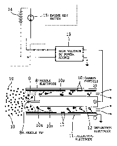
Fig. 1 is a diagram given in explanation of the basic
construction and principles of operation of an electrically
controlled diesel engine exhaust particle collection device
constituting an embodiment of the present invention; Fig. 2
is an exploded perspective view showing the construction of
this exhaust particle collection device in exploded form;
Fig. 3 is an electrical layout diagram of this exhaust
particle collection device; Fig. 4 is an axial cross-
9
~18~243
sectional view of a collection unit constituting a major
part of this exhaust particle collection device; Fig. 5 is
an axial cross-sectional view showing this collection unit
disassembled into subunits; Fig. 6 is a perspective view
showing this collection unit from the front (upstream side
of the exhaust gas current); Fig. 7 is a detail view of part
of Fig. 6 to a larger scale; and Fig. 8 is a perspective
view seen from the rear of this collection unit (downstream
side of the exhaust gas current).
The exhaust particle collection device of this example
relates to an exhaust cleaning device wherein carbon
particles (black smoke) present in the exhaust are
electrostatically collected by means of a needle discharge
system, and that is mounted in the exhaust passage of a
diesel engine mounted on a vehicle such as a truck or bus.
First of all, the basic structure and principles of
operation of this example will be described with reference
to Fig. 1.
As shown in Fig. 1, the exhaust particle collection
device of this example is essentially constituted by
providing: a needle electrode 8 for charging up carbon
particles (black smoke) 10, 10, ... by creating a corona
discharge 9 around the needle tip 8a; a collection electrode
11 for collecting these charged-up carbon particles (charged
carbon particles) 10a, 10, ... by electrostatic force; a
deflecting electrode 12 for applying a deflecting force
218743
towards collecting electrode 11 to charged carbon particles
10a, 10a, ...; and a high voltage DC power source 13 for
applying prescribed high DC voltages (in this example, 5 to
6kV) between needle electrode 8 and collection electrode 11
and between deflection electrode 12 and collection electrode
11. Needle electrode 8 has its needle tip 8a, which is
nickel-plated, directed towards the upstream side of the
exhaust passage of the diesel engine and generally
coincident with the common axis; in this example, it is
fixed by welding or swaging or the like to the tip of a
hollow square-rod shaped deflection electrode 12 about lOmm
square and of length 5 to 6cm. In this way, an electrode
assembly of a needle electrode 8 and deflection electrode 12
arranged generally on a common axis is formed.
For collection electrode 11, a tunnel-shaped electrode
(about 20mm square, length 5 to 6cm) providing a passage for
the exhaust gas is constituted by assembling four flat
plate-shaped metal plates; an electrode assembly consisting
of needle electrode 8 and deflection electrode 12 is
arranged generally coaxially with the axis of the tunnel
within the tunnel of collection electrode 11. Also, high
voltage DC power source 13 consists of a DC-DC conversion
circuit that steps up the DC voltage of 24V that is supplied
from the vehicle-mounted battery 14 to DC 5 to 6kV and
outputs this. The positive-polarity output terminal is
connected to the electrode assembly (deflection electrode
11
2187243
12), while the negative-polarity output terminal is earthed.
Collection terminal 11 itself is also earthed.
In the above construction, when the engine key switch
(ignition switch) 15 is turned ON, the engine is started
and, simultaneously, DC voltage of 24V is supplied to high-
voltage DC power source 13 from battery 14. When high
voltage DC power source 13 receives the DC voltage of 24V,
it generates high voltage of DC 5 to 6kV, which is then
output to the electrode assembly (needle electrode 8 and
deflection electrode 12 of mutually equal potential).
Needle electrode 8 and deflection electrode 12 thereby
become of high potential. However, in particular, since the
electric field is concentrated at the needle tip 8a of
needle electrode 8, a corona discharge 9 is generated
continuously in stable fashion around needle tip 8a.
Consequently, when the gas molecules of comparatively low
ionization energy such as residual oxygen in the exhaust gas
from the diesel engine pass this point, they are ionized,
becoming plasma ions, which are adsorbed on to the carbon
particles 10, causing the particles themselves to have a
positive ionic charge. In this way, those of carbon
particles 10a that are thus charged and which are close to
collection electrode 11 are adsorbed on to the electrode
plates of collection electrode 11, which are of negative
potential. In contrast, charged carbon particles 10a, 10a,
... that are further from the electrode plates of collection
12
2187243
electrode 11 are first of all deflected (repelled) in the
direction of collection electrode 11 by the positive
potential of deflection electrode 12. When they approach
collection electrode 11, they are adsorbed on to the
electrode plates of negative-potential collection electrode
11. Consequently, very fine particles from about O.Olpm up
to comparatively large carbon particles 10, 10, ... of about
l0~un can be efficiently collected.
Next, the detailed construction of the exhaust particle
collection device of this example will be described with
reference to Fig. 2 to Fig. 8.
The exhaust particle collection device of this example
consists, in outline, of two front and rear box-shaped
collection units 16, 16 consisting of a large number of
needle electrodes 8, 8, ..., deflection electrodes 12, 12,
..., and collection electrodes 11, 11, ..., together with
high voltage DC power source 13, and a device casing 17 that
receives and holds these.
As shown in Fig. 2, on the upper face of device casing
17, there are mounted a pair of mounting fittings 19, 19 for
mounting and fixing the exhaust particle collection device
of this example to vehicle body 18; at its corner it is
formed with a through-hole to allow the passage of leads 20,
20 connected to the input terminal of high voltage DC power
source 13. At the front face of device casing 17, as shown
in Fig. 3, there is provided an exhaust inlet 22 of tubular
13
21~724~
shape fitted with a flange 21, and connected through flanges
21, 24 to an exhaust passage 23 downstream of the silencer,
not shown, whereby exhaust gas 25 discharged from the diesel
engine flows into the interior of device casing 17. On the
rear face of device casing 17, there is provided an exhaust
gas outlet 26 of tubular shape, whereby exhaust gas 27 from
which the black smoke has been removed is discharged into
the external environment. Also, a pivotable lid 28 is
provided on one side face of device casing 17 so that
collection units 16, 16 can be removed or inserted. Within
the interior of device casing 17, with a prescribed
separation between them, there is provided a pair of two
floor rails 29, 29 arranged parallel to the front face, and
two ceiling rails 30, 30 arranged at positions facing
respective floor rails 29, 29, the construction being such
that collection units 16, 16 are inserted into and held
lined up in the forwards/rearwards direction in such a
manner that they can be freely removed, by sliding forwards
into the interior in a condition with collecting units 16,
16 fitted on to floor rails 29, 29 and the corresponding
ceiling rails 30, 30. It should be noted that although not
shown in Fig. 3, in the condition with collecting units 16,
16 inserted and held in device casing 17, the exhaust gas 25
that flows from exhaust inlet 22 into device casing 17 must
inevitably pass successively through collection units 16, 16
before being discharged to the external environment.
14
2 ~ ~72~3
As shown in Fig. 5, each collection unit 16 consists of
a slotted-together structure of convex electrode subunit 31
and concave electrode subunit 32 which are both box-shaped
and electrically isolated and, as shown in Fig. 4, Fig. 6
and Fig. 7, which have inserted therein electrode assemblies
consisting of needle electrodes 8, 8 within each tunnel of
collection electrodes 11, 11, ..., of which a large number
are arranged in lattice fashion, and deflection electrode
12, 12, ... Assemblies obtained by fitting together a
plurality of metal plates 11a, 11b, ... vertically and
horizontally in a mutually orthogonal condition with
separation of about 20mm on a square metal frame 33 having
openings at front and back are combined to produce a concave
electrode subunit 32 wherein a large number of tunnel-shaped
collection electrodes 11, 11, ... of about 20mm square and
length 5 to 6cm are arranged in lattice fashion.
Also, a convex electrode subunit 31 is constituted by
electrode assemblies (the same number as collection
electrodes 11, 11, ...), in which needle electrodes 8, 8,
... project at the tips of deflection electrodes 12, 12, ...
in a condition with the needle tips 8a, 8a, ... directed
towards the exhaust inlet 22, being arranged in lattice
fashion at positions corresponding, in one to one fashion,
to collection electrodes 11, 11, ... These electrode
assemblies are supported and fixed with metal linkage
members 34, 34 assembled in the vertical and horizontal
218'243
directions into a unit and linked together. These linkage
members 34, 34 are connected through leads 20, 20 to the
output terminal of the high voltage side of high voltage DC
power source 13 and high voltages of mutually equal
potentials are thereby applied to all of the needle
electrodes 8, 8, ... and deflection electrodes 12, 12, ...
Linkage members 34, 34, ... are fixed and supported through
electrically insulating members 36, 36, ... of hard resin or
the like on a square support metal frame 35 having an
opening at front and back.
At the front face of metal support frame 35, there is
fixed a square metal frame 37, for purposes of slotting
together, likewise provided with openings at its front and
back faces; by slotting the metal frame 33 of concave
electrode subunit 32 into this slotting-together metal frame
37, concave electrode subunit 32 is mounted in freely
removable fashion within the metal support frame. In this
way, all the collecting electrodes 11, 11, ... which are
arranged in lattice fashion are put into a condition of
electrical contact with device casing 17 through metal frame
33, slotting-together metal frame 37 and metal support frame
35. Thus, since this device casing 17 is earthed when it is
fixedly mounted on vehicle body 18, collecting electrodes
11, 11, ... are also earthed. Furthermore, since
electrically insulating members 36, 36, ... are inserted
between the electrode assemblies (needle electrodes 8, 8,
16
21~7~43
... and deflection electrodes 12, 12, ...) and collecting
electrodes 11, 11, ..., both these are electrically isolated
from each other. It should also be noted that, in this
example, in collecting units 16, 16, the total of the cross-
sectional areas of the gaps of collecting electrodes 11 and
deflecting electrodes 12 that constitute the passage for the
exhaust gas 25 is preferably set to be at least twice as
great as the cross-sectional area of the diesel engine
exhaust passage 25.
In the above construction, as shown in Fig. 3, when the
engine key switch (ignition switch) 15 is turned ON, the
engine is started up and simultaneously voltage of DC 24V is
supplied from battery 14 to high voltage DC power source 13.
When high voltage DC power source 13 receives the voltage of
DC 24V that is supplied, it generates high voltage of DC 5
to 6kV and outputs this to the front and rear collecting
units 16, 16. Needle electrodes 8, 8, ..., of which there
are a large number arranged in lattice fashion, and
deflecting electrodes 12, 12, ... are thereby put at high
potential; however, in particular, since the electric field
is concentrated at the needle tips 8a, 8a, ... of needle
electrodes 8, 8, . . . , corona discharge 9, 9, . . . is
continuously generated in stable fashion around needle tips
8a, 8a, ...
Consequently, when the exhaust gas 25 of the diesel
engine passes over the respective needle tips 8a, 8a, ...,
17
~1~7243
gas molecules of comparatively low ionization energy such as
residual oxygen in the exhaust are ionized, becoming
positive ions, which are adsorbed on to carbon particles 10,
10, ..., conferring a positive ionic charge on the particles
themselves. Of these thus-charged carbon particles 10a,
10a, ..., those nearest the correspondingly collected
electrodes 11, 11, ... are adsorbed on to the electrode
plates of negative-potential collecting electrodes 11, 11,
... In contrast, charged carbon particles 10a, 10a, ... that
are more remote from the electrode plates of collecting
electrodes 11, 11, ... are first of all deflected (repelled)
in the direction of collecting electrodes 11, 11, ... by the
positive potential of deflection electrode 12, and, when
they approach collecting electrodes 11, 11, are adsorbed on
to the electrode plates of negative-potential collecting
electrodes 11, 11, ... It should be noted that the cross-
sectional area of device casing 17 where the exhaust gas 25
discharged from the diesel engine flows into device casing
17 from exhaust inlet 22 is set sufficiently greater than
the orthogonal cross-section of exhaust passage 23 of the
diesel engine, so that the speed of the exhaust gas is
lowered. Consequently, the black smoke can be efficiently
adsorbed on to collecting electrodes 11, 11 before the
exhaust gas is discharged to the external environment.
Consequently, since, in the above construction, sets of
collecting electrodes 11, 11, ..., needle electrodes 8, 8,
18
218724
..., and deflecting electrodes 12, 12, ... are arranged in
lattice fashion and also arranged in two stages i.e. front
and back, a continuous stable curtain of corona discharge is
formed over a wide range at two locations at the front and
at the back. Consequently, carbon particles 10, 10, ... can
be collected in reliable fashion. Consequently, continuous
and stable corona discharges 9, 9, ... can be obtained and
also, since the diameter of the trunk portion is large,
outstanding black smoke collection ability and durability
can be obtained even under severe conditions such as when
mounted in a vehicle.
[B~ Second embodiment
Fig. 9 is an exploded perspective view showing the
construction of an electrically controlled diesel engine
exhaust particle collection device according to a second
embodiment of this invention; Fig. 10 is a diagrammatic
axial cross-sectional view showing the construction of this
exhaust particle collection device; and Fig. 11 is a view
showing the construction of a baffle plate incorporated in
this exhaust particle collection device, (a) being a back
face view while (b) is a side face view;
The principal difference between the exhaust particle
collection device of this example and the first embodiment
described above is that a baffle plate 38 for reducing the
19
2i~7243
speed of exhaust gas 25 is inserted between exhaust gas
inlet 22 and the front-stage collection unit 16.
By providing such a baffle plate 38, the speed of the
exhaust gas 25 can be further reduced, so further increasing
the reliability of black smoke collection.
(C] Third embodiment
Fig. 12 is a diagrammatic axial cross-sectional show
showing the construction of an electrically controlled
diesel engine exhaust particle collection device according
to a third embodiment of the present invention; and Fig. 13
is a view showing the construction of a baffle plate
incorporated in this exhaust particle collection device, (a)
being a rear face view while (b) is a side face view;
In this example, in place of the baffle plate 38 of the
second embodiment, a baffle plate 38a formed with a large
number of small holes 39, 39, ... in the vicinity of its
center in radial fashion is employed.
By means of the construction of this example, generally
the same effect as in the second embodiment described above
can be obtained. In addition, the benefit can be expected
that this arrangement is preferable from the point of view
of fluid dynamics in that the eddies which are liable to
form at the rear face of the plate can be prevented. It
should be noted that small holes 39, 39, ... do not
~1~7243
necessarily have to be distributed radially, but could be
dispersed in irregular fashion.
[D] Fourth embodiment
Fig. 14 is a diagrammatic axial cross-section showing
the construction of an electrically controlled diesel engine
exhaust particle collection device according to a fourth
embodiment of the present invention.
In the exhaust particle collection device of this
example, in addition to the construction of the third
embodiment described above, for example an auxiliary mesh 40
for purposes of flow-speed reduction consisting of
refractory material such as stainless steel is provided
immediately downstream of baffle plate 38a. With the
construction of this example, in addition to some of the
black smoke being adsorbed on to the speed-reduction
auxiliary mesh 40, the exhaust gas 25 is considerably slowed
down, so the efficiency of black smoke collection can be
reliably increased yet further than in the case of the
construction of the second embodiment.
Although embodiments of the present invention have been
described in detail with reference to the drawings, the
specific construction is not restricted to that of these
embodiments, and design modifications etc. that do not
21
218723
depart from the essence of the present invention are also
included in the present invention.
For example, the shape and number of needle electrodes
8, collecting electrodes 11, and deflection electrodes 12
can be modified as required and the number of collection
units 16 can be increased or decreased as required. Also,
although, in the embodiments described above, the case was
described in which the exhaust particle collection device
was mounted downstream of the silencer, there is no
restriction to this, and it could be mounted upstream of the
silencer. Also, conductive ceramics could be employed as
the structural material of the collecting electrodes 11
instead of metallic material.
22