Note: Descriptions are shown in the official language in which they were submitted.
2 ~ 87~~~
A METHOD AND AN APPARATUS FOR MANUFACTURING WIRE
Field of Invention
This invention relates to a method and an apparatus for
manufacturing wire, particularly for manufacturing wire with a
diameter less than 5.5 mm
Background of Invention
As conventional methods for manufacturing metal wire, metal
drawing process, metal rolling process and combinational process
of said two ones have been known. The metal drawing method has
been used mainly for manufacturing fine wire, wherein work
material is successively drawn trough a plurality of drawing dies,
wherein the sizing passes successively decreases. On the other
hand, in the metal rolling process, work material is successively
rolled by a plurality of roller-couples which are alternately
arranged so that the angle between the roller axes of adjacent
roller-couples is almost 90°. This process achieves a higher
productivity in comparison with the metal drawing process.
In many cases of the metal rolling process, the two rollers
of each roller-couple have grooves on their rolling surfaces,
respectively, which form a sizing pass for determining the cross
sectional shape of resulting wire. By using an oval shape of
sizing pass for upstream roller-couple and a circular shape of
sizing pass for downstream one in adjacent roller-couples, a high
wire productivity is achieved since the reduction of area against
the work material at each pass of rolling increases.
1
2~8772~
The metal rolling process, however, has a problem that work
material (or wire) is sometimes twisted when it is introduced to
the downstream roller-couple from the upstream one. The tendency
of occurring such twisting is rather high in the case that the
shapes of the sizing passes are different between upstream and
downstream roller-couples, particularly in the case of a
combination of oval-circular sizing passes. Anyway, the twisting
of work material may lead to such trouble as irregular cross
section of resulting wire or cutting off of the material.
One of effective methods for preventing the work material
from twisting is using auxiliary roller guides for guiding the
introduction of the work material to the roller-couple. However,
the size of the roller guises be comes smaller with decreasing the
diameter of resulting wire, and it becomes substantially
impossible to use such roller guides when the diameter of the wire
is less than 5.5 mm, so that it has been regarded vary difficult
to produce fine wire with a diameter less than 5.5 mm through the
metal rolling process.
Therefore, in the process of the prior art for manufacturing
such fine wire, first the work material is rolled to the diameter
around 5.5 mm, and next drawn by using drawing dies to a
designated diameter less than 5.5 mm. This process, however, has a
disadvantage that the high productivity of the metal rolling
process is reduced because the metal drawing process, whose
productivity is rather low, should be combined. Furthermore, the
2
2187720
metal drawing process can be applied only for the cold working
process, so that for producing wires of work-difficult materials
such as high speed tool steel or high alloy steel, stress relief
annealing should be performed every designated number of drawing
passes, so that the productivity becomes further worse.
The object of this invention is to offer a method and an
apparatus for manufacturing wire with a diameter less than 5.5 mm
which achieves a high productivity and high quality of wire.
Summary of the Invention
This invention relates to a method and an apparatus for
manufacturing wire by rolling work material successively with a
first roller-couple and a second roller-couple which are arranged
adjacently in a feeding (or transportation) direction of the work
material and roll the work material in different directions each
other.
For accomplishing the aforementioned problem, the method of
this invention is characterized by that the first and second
roller-couples are arranged so that the ratio of L/D is less than
30, where L is a center distance between the first and the second
roller-couples, and D is a wire diameter obtained after the
rolling by the second roller-couple, the work material is rolled
by the roller-couples so that reduction of area of the work
material achieved by each roller-couples is 5 - 35%, and resulting
wire diameter is less than 5.5 mm.
3
2187720
The inventor has discovered that an adjacent arrangement of
the first and the second roller-couples with L/D less than 30 may
effectively protect the work material from said twisting during
rolling without using any roller guides, thereby enabling
production of wire with a diameter less than 5.5 mm by a metal
rolling process and achieving very high efficiency of production
of such fine wire in comparison with conventional method such as
metal drawing process.
The reduction of area of the work material achieved by each
roller-couples is set in a range of 5 - 350: The reduction of area
less than 50 leads to a poor wire productivity, and that exceeding
35~ causes excess degree of working which may lead to a generation
of faults in the work material or damaging the rollers. The
reduction of area is preferably set in a range of 10 - 300.
The apparatus of this invention comprises said first and
second roller-couples. At least one of the first and second
roller-couples can be constructed so as to comprise two rollers
each of which has a groove on the circumferential surface thereof
for forming a sizing pass, which determines the cross sectional
shape of the wire. According to this construction, the cross
section of the wire may be precisely formed in a designated shape.
The optimization for the shapes of the sizing passes of the first
and the second roller-couples may improve the wire productivity
with maintaining high accuracy of dimension and good working
condition of the wire since high reduction of area may be achieved
for each pass of rolling.
4
21 X7720
For achieving a wire diameter less than 5.5 mm, the width of
the grooves is set to be less than 7 mm for the first roller-
couple and less than 6 mm for the second roller-couple. On the
other hand, the wire may by produced by using a roller-couple
having flat rolling surfaces without grooves. In this case, the
clearance formed between two rollers is less than 7 mm for the
first roller-couple and less than 6 mm for the second roller-
couple. In both of the constructions, the center distance between
the first and the second roller-couples, L, is set to be less than
50 mm. The inventor has also discovered that an adjacent
arrangement of the first and the second roller-couples with the
center distance L less than 50 mm may effectively protect the work
material from said twisting during rolling.
For preventing the work material from twisting, the center
distance L is preferably set to be as short as possible with a
range where no interference occurs between the adjacent roller-
couples. Specifically, the center distance L can be determined
according to the outer diameter of each roller. When the outer
diameter, d, of the rollers of the first roller-couple is the same
as that of the second roller-couple, the ratio L/d is preferably
set to be less than 1.2, and more preferably less than 1Ø
The first and second roller-couples may be arranged
alternatingly so that the angle between the rotation axes thereof
is almost 90°. More specifically, the first roller-couple can be
constructed so as to roll the work material so that the cross
2187720
sectional dimension of the work material in a direction of rolling
reduction, D1, becomes shorter than that in a direction
perpendicular to the direction of rolling reduction, D2, and the
second roller-couple rolls the work material so that the ratio of
the dimensions, D2/D1, is decreased. According to this
configuration, a high reduction of area may be achieved for each
pass of rolling, whereby the wire productivity improves.
The sizing passes may be formed in different shapes between
the first and the second roller-couples, whereby the wire
productivity improves while a high dimensional accuracy and a good
working condition are maintained. For example, the sizing pass may
be formed in an oval shape for the first roller-couple and in a
circular shape for the second roller-couple. Such configuration of
sizing passes achieves high dimensional accuracy and productivity
of wire having a circular cross section.
The apparatus can be constructed so that a plurality of
roller-couple units each of which comprises the first and the
second roller-couples can be arranged in the feeding direction of
the work material, and the work material may be successively
rolled by the roller-couple units. According to such
configuration, the work material can be rolled successively, so
that fine wire may be produced even from work material with a
large cross section.
The final diameter of the wire produced is preferably set in
a range of 1.30 - 5.40 mm for achieving high dimensional accuracy
6
2187720
of wire and for suppressing the frequency of faults in the
resulting wire, whereby the superiority in wire productivity
against the conventional method, such as the metal drawing
process, becomes very significant.
Although the variety of the work material is not limited to
a particular one, this invention is particularly advantageous for
producing wire of work-difficult iron-based materials, such as
high speed tool steels, stainless steels and other high alloy
steels, whose efficient production has been regarded to be
difficult. However, this invention can be applied also to any
other iron-based material such as soft steels, cold-workable
carbon steels, alloy tool steels, and non-iron based metals such
as Ni alloy and Ti alloy (for example, Ni-Ti based shape memory
alloy), and so on.
The rolling temperature of the work material can be chosen
arbitrarily according to the variety thereof. For a material with
a high deformation resistance at a room temperature, a high
rolling temperature is preferable for improving wire productivity
since the deformation resistance decreases thereby increasing the
reduction of area. Furthermore, such high rolling temperature may
suppress the increase in the work stress according to the recovery
or the recrystarization of the work material during rolling, so
that no process annealing for stress relief or for reducing
hardness is needed, whereby the advantage in the productivity
becomes more significant.
7
2~~~~~~
In the case of iron-based work material, the temperature of
the material when it is introduced to the first roller-couple is
preferably adjusted in a range of 400 - 1300°C. The temperature
below 400°C makes the effect of decreasing the deformation
resistance insufficient, and that over 1300°C causes oversoftening
of the work material which leads to buckling or twisting thereof,
so that normal rolling becomes impossible.
In the case of using a plurality of roller-couple units for
successively rolling the work material, the temperature of the
material can be maintained in the temperature range mentioned
above when it is introduced into the first roller-couple of the
first unit.
Several kinds of work material have further preferable
temperature range for rolling. For example, high speed tool steels
is preferably rolled in a range of 800 - 1150°C. Rolling
temperature below 800°C deteriorates not only the deformation
resistance of the material but also the ductility, toughness and
post-quenching hardness of the material since micro-voids are
formed in the texture of the material due to cracking of carbides.
On the other hand, temperature over 1150°C causes coarsening of
carbides in the texture of the material, which decreases the
strength of the wire obtained.
The hot-rolling process according to the method of this
invention is preferably performed as follows. The method comprises
steps of continuously removing scale formed on work material in
8
2i X7720
feeding by using a scale-removing device arranged on the passage
of said work feeding, and heating the work material after the
removal of the scale by using a heating device which comprises an
electrode contacting with the work material allowing continuous
feeding thereof and sending electric current into the work
material through the electrode for resistance-heating of the work
material. The heated work material is rolled by using a rolling
mill so that resulting diameter of wire is less than 5.5 mm. Since
the scale formed on the work material is preliminarily removed and
then heated by a resistance heating method through the electrode,
the contact between the work material and the electrode becomes
reliable and stable, and spark generation is suppressed
therebetween, so that high quality of fine wire can be produced
with a large yield.
The heating step may be performed so that the work material
in feeding is heated by a heating device which is arranged on the
passage of said transportation and comprises an induction heating
coil. This configuration comprises no electrode contacting with
the work material, so that no spark occurs during heating whereby
fine wire can be produced with high quality and a large yield.
The distance between the heating device and the rolling mill
is preferably set to be less than 4 m. In the hot-rolling process
for fine wire, the heated work material tends to be cooled quickly
because of its small diameter. In this case, work-difficult
materials, such as high speed tool steels, stainless steels, super
alloys, Ti alloys (for example, Ti-Ni based shape memory alloy s ,
9
218772
and so on, have considerable narrow temperature range suitable for
hot-rolling and apt to occur cracks or other faults during rolling
if the material is cooled below the optimum temperature range.
However, when said distance is set to be less than 4 m, the work
material can be immediately introduced into the roller-couples, so
that said cooling of the material and relating faults may be
effectively prevented. The distance between the heating device and
the rolling mill is more preferably set to be less than 3 m.
The preferable construction of the apparatus for performing
the hot-rolling method mentioned above comprises the afore-
mentioned rolling mill and following elements:
(1) a scale-removing device which is arranged on the passage of
feeding of the work material and continuously removes the scale
formed on said work material in continuous feeding; and
(2) a heating device for heating the work material after the
removal of the scale comprising an electrode contacting with the
work material allowing the feeding thereof and sending electric
current into the work material through the electrode for
resistance-heating of the work material.
The scale-removing device may comprise a shot-blasting
device which removes the scale by blasting a flow of abrasive
particles onto the surface of the work material in continuous
feeding. According to this construction, the scale on the surface
of the work material can be effectively removed.
The heating device can be constructed so as to comprise a
2187720
roller electrode which contacts with the work material and sends
electric current into the work material for its resistance-heating
and an urging mechanism which urges the roller electrode against
the work material. According to this construction, the contact
between the roller electrode and the work material becomes more
reliable. In this case, a groove is preferably formed on the
circumferential surface of the roller electrode for guiding the
feeding of the work material. The urging mechanism may be
constructed as a spring mechanism or a pressure cylinder mechanism
comprising an air or hydraulic cylinder. The pressure cylinder
mechanism comprising an air cylinder is particularly preferable
since the urging pressure of the roller electrode against the work
material can be adjusted easily.
The heating device may be constructed so as to comprise an
induction heating coil for heating said work material in
continuous feeding which is arranged on the passage of the
feeding.
The rolling reduction against the work material by each
roller-couple can be varied according to the variety of the work
material, and the ratio, R1/R2, where Rl and R2 are roller-
rotation rates in the first and second roller-couple,
respectively, can be adjusted according to the rolling reduction.
In this case, the rolling reduction and the ratio R1/R2 can be
varied according to the torsional rigidity of the work material.
The function and effect of this configuration is as follows.
11
2187720
The probability of occurrence of the wire twisting
specifically depends upon the torsional rigidity of the work
material. For example, as is shown in Fig.30 (a), when the rolling
reduction is increased for the first roller-couple, the work
material (A1) is deformed largely in the direction of the
compression (or rolling) between the rollers. The resulting shape
of the cross section of the work material is to be elongated along
the direction perpendicular to said compression and cause a
significant twisting torque upon the work material when a
secondary rolling is performed in the direction crossing to the
primary one. This means that a work material having a low
torsional rigidity is apt to be twisted when the rolling reduction
is increased for the first roller-couple. Therefore, such twisting
of wire may be effectively prevented by adjusting the rolling
reduction according to the variety of the work material,
particularly to the torsional rigidity thereof.
In this case, the change in the rolling reduction at the
first roller-couple causes a change in the reduction of area
achieved thereat, so that the feeding rate of the work material
from the first roller-couple, i.e., the feeding rate to the second
roller-couple should be also changed. Therefore, by changing the
rotation rate of the second roller-couple corresponding to the
change in the feeding rate of the work material, i.e., by changing
the ratio R1/R2, the rolling may be performed smoothly upon the
work material even if the rolling reduction is varied.
On the other hand, the resulting wire diameter can be varied
12
217120
in a designated range by changing the rolling reductions in the
first and second roller-couples against the work material in a
corresponding range. According to this construction, there is no
need to substitute current rollers with other ones having
different configuration of sizing pass for changing the wire
diameter, whereby wires having various diameter can be produced
efficiently.
In the case that the ratio of roller rotation rates R1/R2 is
fixed in a designated value, the total rolling reduction against
said work material by the first and second roller-couples can be
varied so that resulting change in the reduction of area of the
work material is within 10 %. The inventor discovered that even if
the rolling reduction is changed at a fixed value of R1/R2, the
rolling can be maintained in a excellent condition. In other
words, the wire diameter can be changed without changing the
sizing pass of the roller-couple as long as the change in the
reduction of area is within 100. This contributes significantly
for increasing productivity of wires having various diameters. In
this case, the change in the rolling reduction is preferably
maintained within 7o.
If the ratio R1/R2 is varied according to the value of the
total rolling reduction against the work material, the total
rolling reduction can be varied so that resulting change in the
reduction of area of said work material is up to 40 0. When the
rolling reduction exceeds certain upper limit, the reduction of
area at the first roller-couple increases, whereby the increase in
13
217720
the feeding rate of the work material from the first roller-
couple, i.e., to the second one becomes no longer negligible.
However, if the roller-rotation ratio R1/R2 is changed
corresponding to the change in said transportation rate, the
rolling can be performed smoothly even the rolling reduction is
changes in such wider range. In this case, the shapes and/or sizes
of sizing passes of the first and the second roller-couples are
preferably changed according to the value of said total rolling
reduction against said work material for maintaining the cross
sectional shape of the resulting wire in a good condition.
In the case of changing R1/R2, the first and the second
roller-couples can be driven by a common driving means through a
first and a second reduction gear systems, respectively, and the
inter-stand reduction ratio, Q1/Q2, where Q1 is the reduction gear
ratio of said first reduction gear system and Q2 is the reduction
gear ratio of said second reduction gear system, may be varied for
changing the ratio Rl/R2. According to this configuration, a
common driving means is used for the first and the second roller-
couples, so that the construction of the apparatus becomes simple.
Furthermore, in a configuration wherein a plurality of
roller-couple units each of which comprises the first and second
roller-couples are arranged in the feeding direction of said work
material and the work material is successively rolled in each
roller-couple units, the inter-stand reduction ratios Ql/Q2 of the
roller-couple units can be changed synchronously. In this
construction, when the inter-stand reduction ratio is set in a
14
2187720
designated value for one of roller-couple units, the inter-stand
reduction ratios for other roller-couple units are also set in
corresponding values synchronously. According to this
construction, even in the case of using many roller-couple units,
the roller reductions and inter-stand reduction ratios may be
easily changed corresponding to the torsional rigidity of the work
material, and so on.
The clearances between two rollers of the first and second
roller-couples can be changed by a roller-clearance adjusting
mechanism which moves the two rollers of each roller-couple
relatively to and from each other in the direction of rolling
reduction. Such roller-clearance adjusting mechanism can be
constructed so as to comprise bearing portions which rotatively
support the shafts of the two rollers, respectively, and a bearing
rotation mechanism which rotates each bearing portion around an
eccentric axis deviated from a corresponding roller axis in
opposite direction, respectively, thereby moving the two rollers
relatively to and from each other. This configuration accomplishes
a simple and compact mechanism for changing the roller spacing.
The bearing rotation mechanism for the first roller-couple
can be arranged upstream of the first roller-couple, and that for
the second roller-couple can be arranged downstream of the second
roller-couple. This configuration is preferable for accomplishing
the proximate arrangement of the first and the second roller-
couples with a center distant L within 50 mm since no bearing
rotation mechanism is located between these roller-couples, so
2 i 87720
that there is no need to prepare auxiliary roller guides for
guiding the work material to the second roller-couple.
The bearing rotation mechanism can be constructed so as to
comprise first gear portions which are formed on the
circumferences of the bearing portions of the two rollers,
respectively, second gear portions each of which engages with
corresponding first gear portion, and a driving mechanism which
rotates the second gear portions synchronously in opposite
directions each other.
The second gear portions can be specifically constructed as
worms which are axially formed on a worm rotating shaft at an
designated intervals along the longitudinal direction thereof and
whose threads are formed in opposite directions each other. The
driving mechanism drives the worm rotating shaft for rotating said
worms integrally. This configuration accomplishes a simple and
compact construction of the bearing rotation mechanism.
In a further specified construction of the apparatus, the
bearing portion comprises bearing casings which are arranged
corresponding to both end portions of each roller shaft and each
of which has a bearing accommodating hole extending along said
roller shaft, a bearing main body which is accommodated in each
said bearing accommodating hole. In this construction, a bearing
hole is formed in each bearing main body so that the center of
said bearing hole is deviated from the rotation axis of the
bearing main body. Each end portion of each roller shaft is
16
217720
rotatively supported in the bearing hole, and the bearing main
body has the first gear portion on its circumference and is
rotated by the worm engaged with the first gear portion around an
eccentric axis deviated from the rotation axis of the roller.
The bearing hole of the first roller couple can be formed in
the bearing main body deviated from its rotation axis in the
downstream, and the bearing hole of said second roller couple can
be formed in the bearing main body deviated from its rotation axis
in the upstream. In addition, each corresponding worm rotating
shaft van be arranged in the similar manner. This configuration is
preferable for accomplishing the proximate arrangement of the
first and the second roller-couples.
At least one of said first and second roller-couples can be
equipped with a roller thrust adjusting mechanism which moves the
two rollers relatively in the thrust direction thereof and hold
these two rollers at an arbitrary positions in the thrust
direction. As is shown in Fig. l9 (b), the thrust displacement
between two rollers of the roller-couple is one of major factor of
causing wire twisting during rolling. In this case, as shown in
Fig. l9 (a), if these two rollers (101a, 101b) are precisely
positioned, the distance line (U1, U2) between the inner surfaces
of the grooves (161a, 161b) of said two rollers trough the center
(O) of the sizing pass (161c) becomes uniform, thereby providing
uniform compression against the work material. Therefore, the
twisting of the work material becomes to be difficult to occur
since the twisting torque against the work material is suppressed.
17
2187720
Such adjustment of the two rollers in the trust direction
can be performed by using said roller thrust adjusting mechanism,
and the thrust displacement in these two rollers can be dissolved
by an adjustment of the position of each roller (thrust
adjustment, hereinafter). On the other hand, such roller
displacement in the thrust direction may causes an irregularity of
the cross sectional shape of the resulting wire. However,
aforementioned thrust adjustment of the rollers can simultaneously
dissolve such problem. Furthermore, even if the surface accuracy
of the sizing pass is not very high, a designated revel of the
dimensional accuracy of the wire can be secured by such thrust
adjustment.
The roller thrust adjusting mechanism can be constructed so
as to comprise a fixed bearing portion which is provided for at
least one of the two rollers and holds the roller shaft rotatively
and movably in its thrust direction, and a roller sliding
mechanism which is connected to one end portion of the roller
shaft and slides the roller shaft against the bearing portion in
the thrust direction.
The roller sliding mechanism can comprise a shaft holder to
which the end portion of the roller shaft is connected and which
is movable integrally with the roller shaft in the thrust
direction, adjusting screw mechanism which is connected to the
shaft holder directly or indirectly with other member and moves
the shaft holder in the thrust direction according to its screwing
18
or unscrewing operation. According to the operation of such
adjusting screw mechanism, said thrust adjustment of the rollers
can be easily performed.
A further specified configuration can be constructed as
follows. The bearing portion comprises a bearing main body which
has a through hole as a bearing hole in the direction of the
roller shaft and rotatively supports the one end portion of the
roller shaft in the through hole. The shaft holder is movable in
the through hole with the roller shaft in the thrust direction.
The shaft holder has a shaft-like protruding portion which extends
along the axial direction of the roller shaft in the through hole
and the end portion of which protrudes outside from the
corresponding opening of the through hole. On the inner side of
the through hole, a female threaded portion is formed on the end
portion thereof leading to the opening. A male screw member is
screwed on the female threaded portion in a position corresponding
to the intermediary part of the shaft-like protruding portion. A
stopper is mounted on the shaft-like protruding portion for
preventing the male screw member from its relative moving against
the shaft-like protruding portion in the axial direction thereof.
The adjusting screw mechanism moves the shaft holder and the
roller shaft in the thrust direction along with the male screw
member according to the rotation of the male screw member. The
adjusting screw mechanism becomes compact according to this
configuration.
Brief Description of Drawings
19
2181720
In the accompanying drawings:
Fig.l is a perspective view presenting the main part of one
embodiment of the apparatus of this invention;
Fig.2 is a schematic view presenting the cross sectional
shape of the sizing passes of the first and the second roller
couples;
Fig.3 is a top view presenting the main part of one
embodiment of the apparatus of this invention;
Fig.4 is a cross sectional side view presenting one
embodiment of the apparatus of this invention;
Fig.S is a schematic top view presenting the bearing
rotation mechanism in Fig.4;
Fig.6 is a cross sectional side view of the first roller
stand;
Fig.7 is a front view presenting the arrangement of the
bearing main body and the worm rotating shaft;
Fig.8 is a schematic side view of Fig.7;
Fig.9 is a schematic top view presenting the states of the
first roller-couple for rolling wires with various diameters;
Fig.lO is a schematic view presenting several modifications
of the shape of the sizing pass;
Fig.l1 is a schematic view presenting other example of the
change in the cross sectional profile of work material;
Fig. l2 is a top view conceptually presenting an apparatus
comprising a plurality of roller-couple units;
Fig.l3 is a schematic view presenting several examples of
the change in the~cross sectional profile of work material
according to a successive rolling by the plural roller-couple
218724
units;
Fig.l4 is a perspective view presenting the main part of an
embodiment of the apparatus having flat rollers;
Fig.l5 is a figure explaining the function of the first and
second roller-couples in Fig. l4;
Fig. l6 is a cross sectional side view of an apparatus
equipped with a roller thrust adjusting mechanism;
Fig. l7 is a figure explaining the function of the roller
thrust adjusting mechanism;
Fig.l8 is an another figure explaining the function of the
roller thrust adjusting mechanism;
Fig. l9 is a figure explaining the influence of thrust
displacement of the rollers upon the work material;
Fig.20 is a sectional view conceptually presenting one
embodiment of a hot-rolling line for wire production;
Fig.21 is a schematic view of a shot-blasting device;
Fig.22 is a figure presenting a main part of an example of
resistance-heating device with along the function thereof;
Fig.23 is a schematic view presenting an example of a
heating device comprising movable roller electrode
Fig.24 is a figure explaining the function of the heating
device in Fig.23;
Fig.25 is a figure of an induction heating device;
Fig.26 is a side view conceptually presenting a rolling
apparatus equipped with a distributor and a reduction gear
mechanism;
Fig.27 is a schematic view presenting the reduction gear
mechanism;
21
Fig.28 is a figure explaining the method to change the
inter-stand reduction ratio;
Fig.29 is a figure presenting how the inter-stand reduction
ratios of plural roller-couple units are changed synchronously;
Fig.30 is a figure explaining how the wire twisting occurs;
Fig.31 is a figure presenting how the wire diameter is
varied by changing in the roller-spacing.
Detailed Description of the Preferable Embodiments
Several embodiments of this invention will now be described
with reference to drawings.
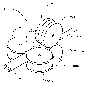
Fig.1 presents the main part of one embodiment of the
apparatus regarding this invention for manufacturing wire. by metal
rolling process ("rolling apparatus", hereinafter). In the rolling
apparatus 1, a first roller stand (horizontal stand) 12 comprising
a first roller-couple 101a,101b is arranged on an unillustrated
mill floor so that the roller axes is almost vertical to the mill
floor, and a second roller stand (vertical stand) 14 comprising a
second roller-couple 102a,102b is arranged adjacently to the first
roller stand 12 on the downstream thereof along the feeding
passage of work material A1 so that the roller axes is almost
horizontal. These roller stands 12 and 14 construct a roller-
couple unit S1. The angle between the roller axes of adjacent
roller-couples 101a,101b and 102a,102b is almost 90°.
As shown in Fig.2, the roller-couples 101a,101b and
102a,102b have rolling surfaces 151a,151b and 152a,152b on
respective circumferences, and grooves 161a,161b and 162a,162b for
22
2187120
determining the cross sectional shape of resulting wire are formed
on respective rolling surfaces 151a,151b and 152a,152b. The width
W1 of the grooves 161a,161b is less than 7 mm, and the width W2 of
the grooves 162a,162b is less than 6 mm. As is shown in Fig.2 (a),
in the first roller-couple 101a,101b, an oval sizing pass 161c is
formed as the combination of the grooves 161a,161b, and in the
second roller-couple 102a,102b, a circular sizing pass 162c is
formed as the combination of the grooves 162a,162b.
As is shown in Fig.3, the center distance L between the
first and the second stands 12 and 14 is less than 50 mm, and the
ratio of L/d, where d is the outer diameter of the rollers
lOla,101b and 102a,102b, is less than 1.2.
Fig.4 is a cross sectional side view of the first and the
second roller stands 12 and 14. These two roller stands 12 and 14
have almost the same configurations except for the direction of
the roller axes. Therefore, the detailed description is presented
only for the first roller stand 12, and the same portions or the
members of the second roller stand 14 are indexed with the same
numerals as those for the first one.
In the first roller stand 12, a pair of bearing casings 24
are arranged on both sides of the feeding passage (or pass line)
PL of the work material A1. Each bearing casing 24 has a bearing
accomodating hole 24a formed along the direction intersecting with
the pass line PL. Each bearing accomodating hole 24a rotatively
accommodates a bearing main body 26 wherein a through hole 26a as
23
2187720
a bearing hole is eccentrically formed. In these through hole 26a,
both end portions of a roller shaft 28 are rotatively supported by
a bearing 30, respectively. On the intermediary portion of the
roller shaft 28, a roller 101a (or 101b: represented by 101a,
hereinafter) is integrally mounted. As shown in Fig.S (a), the
axis C1 of the roller shaft 28 is located deviating from the axis
C2 of the bearing main body 26 at a designated distance. The axes
C1 for rollers 101a,101b in opposite direction are to be displaced
by the rotation of the corresponding bearing main bodies 26
according to the mechanism described later on.
As shown in Fig.4, on the upstream of the roller shaft 28, a
pair of worm rotating shaft 32 are arranged in a direction
crossing over the roller shaft 28. The worm rotating shaft 32 is
provided on each side with respect to the first roller-couple
lOla,101b (Fig.1), and as shown in Fig.5, worms 34 are integrally
mounted thereon corresponding to upper and lower bearing main
bodies 26 and engage with the gear portions 26b formed on the
circumferences of the corresponding bearing main bodies 26,
respectively (see also Fig.8). As shown in Fig.5, the direction of
threads of the two worms 34 on each worm rotating shaft 32 are
opposite each other. On the other hand, as shown in Fig.7, the
threads of worms 34 corresponding to both end portions of the same
roller shaft 28 are formed in the same direction.
As shown in Fig.7 and Fig.8, on the corresponding end
portions of two worm rotating shafts 32,32, gears 36,36 are
secured so as to rotate integrally with corresponding worm
24
. 2187720
rotating shafts 32, respectively. These gears 36 engage with an
adjusting gear 38 which is rotatively mounted on the bearing
casing 24. The adjusting gear 38 is rotated by an unillustrated
driving means, such as a motor, whereby said two worm rotating
shafts 32,32 rotate simultaneously in the same direction. Thus, as
shown in Fig.S (b), the bearing main bodies 26 rotate around the
axis C2 through corresponding worms 34, and the upper and lower
roller shafts 28,28 move to or form each other, whereby the
clearance between the roller shafts, 28,28 i.e, the clearance
between the rollers 101a,101b is adjusted.
As shown in Fig.4, there is no worm rotating shaft 32 as a
bearing rotating mechanism is located downstream of the bearing
casing 24, where the roller shaft 28 is eccentrically arranged, so
that the thickness of the first roller stand 12 is decreased on
that side. The thickness of the second roller stand 14 located
upstream of the bearing casing 24 is also decreased due to the
same reason. Since these two stands 12 and 14 are adjacently
arranged so that the small thickness sides thereof are facing to
each other, the center distance L between the first and the second
roller-couples 101a,101b and 102a,102b becomes short.
Now, the operation of the rolling apparatus 1 is going to be
explained in the following. As is shown in Fig. l, the work
material A1 having a circular cross section with a diameter DO is
introduced to the first roller stand 12 and rolled in the sizing
pass 161c so that the shape of the cross section becomes oval as
shown in Fig.2 (a). After that, as shown in Fig.2 (b), work
2187720
material A1 is fed to the second roller stand 14 (Fig.1) and
rolled in the sizing pass 162c so that the shape of the cross
section becomes circular. Thus, the cross section of the work
material A1 successively decreases with alternately varying the
shape thereof as circular - oval - circular as shown in Fig.2 (c).
The work material A1 is rolled in the first roller stand 12 so
that the cross sectional dimension thereof in a direction of
rolling reduction, D1 (corresponding to the short axis of oval),
becomes shorter than that in a direction perpendicular to the
direction of rolling reduction, D2 (corresponding to the long axis
of oval). Then, in the second roller stand 14, since the direction
of rolling-compression is changed by 90°, the work material A1 is
rolled so that the ratio of the dimensions, D2/D1, is decreased
(i.e., (D2/D1) > (D2'/D1'), where D1' and D2' are corresponding
dimensions after rolling).
Since the first and the second roller stand 12 and 14 are
adjacently arranged so that the center distance L between the
first and second roller-couples 101a,101b and 102a,102b is less
than 50 mm as shown in Fig.3, the work material A1 from the first
stand 12 can be precisely supplied to the second one 14 causing no
twisting of itself without any aid of roller guides. The final
diameter of produced wire W2 is preferably set in a range of 1.30
- 5.40 mm for achieving high dimensional accuracy of the wire and
for suppressing the frequency of the faults in the resulting wire,
whereby the superiority in wire productivity to the conventional
method such as the metal drawing process becomes very significant.
For this purpose, the width W1 of the grooves 161a,161b (Fig.2) is
26
21$7720
preferably set to be less than 7 mm, and the width W2 of the
grooves 162a,162b is preferably set to be less than 6 mm.
The roller spacing can be changed in such way as follows
(explained according to an example for the first roller stand 12,
representatively). As shown in Fig.9, when the work material A1 is
switched to that having a larger cross sectional dimension, A2,
the roller-couple lOla,lOlb should be replaced with the ones
101a',lOlb' with wider width of grooves 161a,161b and larger
diameter. The distance between the shaft axes is also changed
from G1 to G2. According to the construction described above,
necessary adjustment can be performed in a very easy operation.
That is to say, as shown in Fig.7, the worm rotating shafts 32,32
are rotated in the same direction forwardly or reversely by the
driving means through the gears 36 and the adjusting gear 38.
Then, as shown in Fig.5 (a) and (b), the bearing main bodies 26
rotate around the axis C2, the upper and the lower roller shafts
28,28 moves to or from each other according to the rotation
direction of the bearing main bodies 26, whereby the roller
clearance is adjusted. The roller-couples can be driven
independently by corresponding motors for the adjustment of said
clearance.
The combination of the sizing passes 161c and 162c is not
limited to the oval-circular one. Fig.lO presents an example of
combination of rhombic and square sizing passes 161c and 162c. The
work material is to be rolled into wire A2 having a square cross
section. Furthermore, according to the choice of combination of
27
217720
sizing passes 161c and 162c presented in Fig.ll, the work material
A2 can be rolled successively changing the cross section as
square-oval-circular, and so on.
As shown in Fig. l2, the wire A2 rolled in the first roller-
couple unit S1 can be further rolled into wire A3 having a smaller
diameter by using another similarly constructed roller-couple unit
S2 which comprises roller stands 212 and 214 having smaller sizing
passes and is arranged adjacently to the first one S1 on the
downstream thereof. For performing further many steps of
successive rolling, more than three roller-couple units can be
arranged in a series along the work feeding direction. In this
case, the plural roller-couples are alternately arranged so that
the angle between the roller axes of adjacent roller-couples is
almost 90°.
In the case of using a plurality of roller-couple units,
although the same combination of the sizing passes can be used for
all roller-couple units, different combinations can be also used
for each roller-couple unit. Fig.l3 presents several example of
using two roller-couple units. Fig.l3 (a) and (b) are examples of
using the same combinations for each units, such as oval-circular
or rhombic-rhombic. Fig. l3 (c) presents an example of using
different combinations such as rectangular-square for the upstream
unit S1 and oval-circular for the downstream unit S2.
As is shown in Fig. l4, the wire may by produced by using
first and second roller-couples lOla,101b and 102a,102b which have
28
2187720
flat rolling surfaces 151a,151b and 152a,152b without grooves,
respectively. In this case, as shown in Fig.l5, the clearance W1
between two rollers 101a,101b (i.e., the clearance between the
rolling surfaces 151a,151b) is less than 7 mm, and the clearance
W2 between two rollers 102a,102b (i.e., the clearance between the
rolling surfaces 152a,152b) less than 6 mm.
In such construction of the apparatus, as shown in Fig. l5,
the work material A1 is deformed to be a rectangular cross
sectional one due to the compression between the rollers
101a,101b, and then is deformed between the rollers 102a,102b in a
direction perpendicular to the first compression, thereby running
out therefrom as a wire A2. As shown in Fig. l5 (c), the cross
section of the work material A1 successively decreases with
alternately varying the shape thereof as square - rectangular -
square.
An example of roller thrust adjusting mechanism will now be
explained according to an example for roller 101a in Fig.4. As
shown in Fig.l6, the roller thrust adjusting mechanism 170 is
constructed so as to comprise a fixed bearing portion (or a
bearing) 30 which holds the roller shaft 28 rotatively and movably
in its thrust direction, and a roller sliding mechanism 171 which
is connected to one end portion of the roller shaft 28 and slides
the roller shaft 28 to the bearing portion 30 in the thrust
direction.
The roller sliding 171 mechanism comprises a shaft holder
29
2187720
.,...
172 to which the end portion of the roller shaft 28 is connected
and which is movable integrally with the roller shaft 28 in the
thrust direction, and an adjusting screw mechanism 173 which is
connected to the shaft holder 172 and moves the shaft holder 172
in the thrust direction according to its screwing or unscrewing
operation. The shaft holder 172 comprises a bearing 174, a sleeve
175, a holder main body 176, and so on. The bearing 174 is engaged
with an annular groove 28a which is formed on the circumferential
surface of one end portion of the roller shaft 28, and held by the
sleeve 175 from outside which is provided slidable in the through
hole 26a in its axial direction. Furthermore, annular rib 175a is
formed protruding from the inner surface of the sleeve 175 on one
end portion thereof and engages with the edge portion of the end
surface of the bearing 174.
On the inner surface of the sleeve 175, a female threaded
portion 175b is formed in opposition to the rib 175a with respect
to the bearing 174. The holder main body 176 connected with the
sleeve 175 from inside by means of the male threaded portion 176a
which is formed on its circumferential surface and is screwed in
said female threaded portion 175b. The bearing 174 is clumped
between the rib 175a and the holder main body 176, thereby
prevented from loosening in the thrust direction. The roller shaft
28 is slidable integrally with the shaft holder 172 comprising
said portion and members 174 - 176 so as to be able to rotate by
means of bearing 174.
A shaft-like protruding portion 177 is integrally formed on
2187720
the end surface of the holder main body 176. This portion 177
extends along the axial direction of the roller shaft 28 in the
through hole 26a, and the end portion thereof protrudes outside
from the corresponding opening 26b of the through hole 26a. On the
inner side of the through hole 26a, a female threaded portion 26c
is formed on the end portion thereof leading to the opening 26b. A
male screw member 178 is screwed on the female threaded portion
26c in a position corresponding to the intermediary part of the
shaft-like protruding portion 177. The male screw member 178 has a
through hole 178a wherein the shaft-like protruding portion 177 is
extending in its axial direction, and is rotatably held around the
portion 177. These female threaded portion 26c and the male screw
member 178 constructs said adjusting screw mechanism 173.
The end surface of the male screw member 178 is contacting
with the edge portion of corresponding end surface of the holder
main body 176. On the other hand, the opposite end surface of the
male screw member 178 is contacting with a nut 179 screwed on the
male thread 177a formed on the outer surface of the protruding
portion 177. These holder main body 176 and nut 179 function as a
stopper for preventing the male screw member 178 from its relative
movement to the shaft-like protruding portion 177 in the axial
direction thereof. On the other hand, a lock nut 180 is screwed on
the male screw member 178 and secured toward the bearing main body
26 for preventing the male screw member 178 from loosening.
Furthermore, the nut 179 also functions as a lock nut for the male
screw member 178.
31
211720
The adjusting screw mechanism 173 is operated in the
following manner for the thrust adjustment of the roller 101a. As
shown in Fig. l7 (a), for the roller needed to be adjusted
(represented by the roller 101a), the lock nut 180 is loosened,
and subsequently the nut 179 is loosened so as not to occur an
excess loosening thereof in the axial direction. In the case of
moving the roller 101a toward the adjusting screw mechanism 173
(right on the figure), the male screw member 178 is rotated so as
to move to right on the figure as shown in Fig. l7 (b). The male
screw member 178 urges the shaft holder 172 and the roller shaft
28 through the nut 179, and moves them integrally to the right.
When the new position of the roller 101a is determined, the lock
nut 180 and the nut 179 are successively secured in this order,
and the operation of the adjustment is to be finished. On the
other hand, in the case of moving the roller lOla leaving from the
adjusting screw mechanism 173 (left on the figure), the male screw
member 178 is reversely rotated. As shown in Fig. l8, the male
screw member 178 urges the shaft holder 172 and the roller shaft
28 through the holder main body 176, and moves them integrally to
the left. When the new position of the roller 101a is determined,
the lock nut 180 and the nut 179 are successively secured in this
order.
In the case of using work-difficult materials, such as high
speed tool steels, stainless steels, high alloy steel or Ti-Ni
based shape memory alloys, it is advantageous to elevate the
rolling temperature for decreasing the deformation resistance,
whereby improving the productivity of wire. Therefore, the work
32
2i X7720
material can be heated before rolling in the first roller stand
12. As is shown in Fig.3, the work material can be heated by a
heating device which comprises electrodes 71a,71b contacting with
the work material A1 allowing the feeding thereof. Electric
current is sent into the work material A1 from the electric power
unit 72 through the electrode 71a,71b. The work material is to be
heated by its own resistance-heat generation.
Fig. 20 presents one of preferable embodiments of hot-
rolling line 401 for the wire production. This line 401 comprises
an uncoiler 2 for drawing the work material A1, such as of a high
speed tool steel or a stainless steel, from the coil thereof. The
work material A1 drawn off by the uncoiler 2 is fed to a scale
removing device 4 via a roller leveling device 3.
The scale-removing device 4 is constructed as a shot-
blasting device. As shown in Fig.2l, this device 4 removes the
scale from the work material A1 by blasting a flow of abrasive
particles 114b from rotary nozzles 114a onto the surface of the
work material A1. The abrasive particles 114b is collected at the
bottom of the housing 114c, elevated by a bucket conveyor 114d,
and then mixed with a gas flow from an unillustrated source, such
as a blower, and then supplied to the rotary nozzles 114a again.
As shown in Fig.20, the work material A1 after the removal
of the scale is fed to the heating device 5. As shown in Fig.22,
the heating device 5 comprises first and second water cooled
roller electrodes 51,52 and 53,54 which contact with the work
33
218772
material A1 and send electric current thereinto for the
resistance-heating thereof, corresponding first and second air
cylinders 55,56 and 57,58 as urging mechanism which urges said
roller electrodes 51,52 and 53,54 against the work material A1,
and an electric power unit 59 (Fig.20) as a source of said
electric current for heating. On the circumferential surfaces of
roller electrode 51-54, grooves 51a-54a are formed, respectively,
for guiding the transportation of the work material A1. The cross
sections of grooves 51a-54a are formed in a shape corresponding to
the shape of the work material A1, for example in a semicircular
shape for a work material A1 having circular cross section.
As is shown in Fig.20, the work material A1 heated by the
heating device 5 is rolled by the rolling mill 6 (or the rolling
apparatus), cooled in a water-cooling device 7, and then wound in
a coil by a coiler 8. In the rolling mill 6, a plurality of
aforementioned roller-couple units S are arranged along the
direction of material feeding. The distance K between the heating
device 5 and the rolling mill 6 is set to be less than 4 m, where
K is defined as the distance from the second roller electrodes
53,54 and the entrance of the first roller-couple unit S.
Now, the operation of the hot rolling line 40 is going to be
explained in the following. After leaving the roller levering
device 3, the work material A1 is removed the scale in the shot-
blasting device 4, and resistance-heated between the first and the
second roller electrodes 51,52 and 53,54 to a designated
temperature. The material temperature can be controlled by the
34
21~7i20
adjustment of the electric current between the electrodes 51,52
and 53,54.
Since the scale is preliminarily removed from the surface of
the work material A1 by using the shot-blasting device 4, the
contact between the work material A1 and the electrodes 51-54
becomes more reliable, whereby spark generation is suppressed
therebetween. Furthermore, since the grooves 51a-54a is formed
corresponding to the cross sectional shape of the work material
A1, the spark generation due to imperfect contact is prevented
more effectively. When the cross section of the work material A1
is circular with a diameter of D0, the radius R of the
semicircular cross section of the grooves 51a-54a is preferably in
the range of 1.05x(DO/2) <_ R <_ 5.Ox(DO/2) for preventing the spark
generation.
When the work material A1 is heated over 1000°C, the
deformation resistance of the material becomes considerably low,
so that the urging pressure from the second roller electrodes
53,54 is preferably set to be lower than that from the first
roller electrodes 51,52 for preventing the work material A1 from
undesirable deformation due to the friction from the electrodes,
such as buckling. The urging pressure can be adjusted by changing
the pressure of the air cylinders 55-58.
The heating device 5 can be constructed so that at least one
of first and second electrodes 51,52 and 53,54 is provided movably
in the transportation direction of the work material A1, whereby
217720
the interval between the electrodes 51,52 and 53,54 becomes
variable during heating of at least one of the tip and the tale
end portions of the work material A1. According to this
construction, the material yield improves since insufficiently
heated part is hardly formed in the tip or the tale end portion of
the work material A1.
In the embodiment presented in Fig.23, the rollers 51,52 and
the rollers 53,54 are rotatively mounted on electrode holders 121
and 131, and driven by motors 122 and 132, respectively. The
electrode holders 121 and 131 are reciprocated by air cylinders
123 and 133, respectively, in the feeding direction of the work
material A1, or in the reverse direction thereof.
The work material A1 from the scale removing device 4
(Fig.20) is fed to the heating device 5 at a rate v. As shown in
Fig.24, electric current is started to be supplied to the work
material A1 when the tip end portion thereof is protruded from the
second roller electrodes 53,54 by a length 11. As shown in Fig.24
(c) through the state of (b), the air cylinder 133 (Fig.23)
retracts a rod 133a thereby moving the roller electrodes 53,54
along with the work material A1 at a rate v', and stops the
retraction of the rod 133a when the interval between the
electrodes 51,52 and 53,54 ("electrode interval', hereinafter)
reaches to a value lo, which is sufficient for accomplishing a
designated heating efficiency. Then, as shown in Fig.24 (d), the
electrode interval is fixed to 10, and the work material A1 is
started to be resistance-heated being transported at the rate v.
36
2187720
The tip portion of the work material Al thus passes through the
heating device 5, next the part of length 11 without being
resistance-heated and following insufficiently heated part of
length 12, i.e., 11+12 in total, are cut off by an unillustrated
cutting device, and then the rest of the work material is supplied
to the rolling mill 6.
On the other hand, when the length of the rest of the work
material A1 becomes said 11+12, the air cylinder 123 starts to
move the first roller electrodes 51,52 in the direction of work
feeding at the rate v', and when the electrode interval reaches to
12, the cylinder 123 stops moving electrodes 51,52. Then, the
electric current supply to the work material is interrupted, and
the tale end portion of the work material A1 with a length 11+12
is cut off by a cutting device. Although the cutting length of
respective tip and tale portions of the work material A1 is 10+11
if the electrode interval is fixed, the cutting length becomes
11+12 which is much shorter than the aforementioned one according
to the construction described above whereby improving the yield of
the work material A1 improves.
Instead of resistance-heating device, the work material A1
can be heated by means of an induction heating device. In this
case, the scale removing device 4 and resistance-heating device 5
in Fig.20 is substituted with an induction heating device 44 as
shown in Fig.25. The induction heating device 44 is formed in a
tunnel-like configuration having an entrance 44a and an exit 44b,
and comprises an induction heating coil 44c. The work material A1
37
2181720
entered therein from the entrance 44a is continuously heated by
the induction heating coil 44c and runs out from the exit 44b. In
this case, if the distance from the exit 44b to the rolling mill 6
is set to be less than 4 m, the cooling of the work material A1
can be effectively suppressed.
Now, an example of rolling apparatus whose roller-couples
are driven by a common driving means will be conceptually
described in the following. As shown in Fig.26, the roller couples
101,102 of the unit S1 and the roller-couples 201,202 of the stand
S2 is driven by a motor 252 as said common driving means through a
distributor 250 and reduction gear mechanisms 253-256 each of
which corresponds to each said roller-couple. The rotation of the
motor 252 is reduced at each reduction gear mechanism 253-256
according to a designated reduction ratio and transmitted to
corresponding roller couple 101,102,201,202 through the
distributor 250.
Fig.27 schematically presents the reduction gear mechanisms
253,254 for the upstream roller stand S1. The reduction gear
mechanism 253 comprises plural gears J1-J3 (tooth numbers are N1-
N3, respectively) which are secured on a driving shaft 300 driven
by the motor 252, and plural gears K1-K3 (tooth numbers are M1-M3,
respectively) which are secured on a transmitting shaft 301 for
the roller-couple 101 and engage directly or indirectly through
other gears with said gears J1-J3, respectively. According to a
relative sliding between the driving shaft 300 and the
transmitting shaft 301, one of the gears Kl-K3 is to be engages
38
2187720
with corresponding one of the gears J1-J3. The rotation of the
motor 252 is thus reduced according to the reduction gear ratio Q1
which is determined as the tooth number ratio of the engaging
gears (Nl/M1 in Fig.27), whereby the rotation rate R1 of the
roller-couple 101 is to be determined to a corresponding value.
The reduction gear mechanism 254 comprises plural gears J4-
J6 (tooth numbers are N4-N6, respectively) which are secured on a
driving shaft 302 driven by the motor 252, and plural gears K4-K6
(tooth numbers are M4-M6, respectively) which are secured on a
transmitting shaft 303 for the roller-couple 102 and engage
directly or indirectly through other gears with said gears J4-J6,
respectively. According to a relative sliding between the driving
shaft 302 and transmitting shaft 303, one of the gears K4-K6 is to
be engaged with corresponding one of the gears J4-J6. The rotation
of the motor 252 is thus reduced according to the reduction gear
ratio Q2 which is determined by the tooth number ratio of the
engaging gears (N4/M4 in Fig.27), whereby the rotation rate R2 of
the roller-couple 102 is to be determined to a corresponding
value.
As is shown in Fig.29, the reduction mechanisms 255,256 has
almost the same construction as those of said mechanisms 253,254,
except for the reduction ratios. The former one 255 comprises
gears J7-J9 on a driving shaft 304 and gears K7-K9 on a
transmitting shaft 305, and the latter one 256 comprises gears
J10-J12 on a driving shaft 306 and gears K10-K12 on a transmitting
shaft 307.
39
2187720
For example, in the roller stands S1 and S2, the inter-
stand reduction ratio Q1/Q2, i.e., the ratio of the roller
rotation rate Rl/R2 between the first and the second roller-
couples 101 and 102 can be selected from designated plural values
according to the torsional rigidity of the work material A1. The
rotation rate is lower for the first roller-couple 101 than for
the second one 102, so that Q1>Q2. Therefore, the inter-stand
reduction ratio Q1/Q2 decreases with decreasing the rotation rate
R2 of the second one 102. As shown in Fig.28, the inter-stand
reduction ratio Ql/Q2 can be changed, for example, by changing the
reduction gear ratio Q2 for the second roller-couple 102 (N4/M4 -
N5/M5, for example) while fixing the reduction gear ratio Q1 for
the first roller-couple 101 to a designated value (N1/M1, for
example). Furthermore, as shown in Fig.29, when the inter-stand
reduction ratio Q1/Q2 of the roller-couple unit S1 is changed to
Q1'/Q2', the ratio Q3/Q4 of the roller-couple unit S2 is
synchronously changed to Q3'/Q4'.
Now, the operation of the rolling apparatus described above
is going to be explained in the following. First of all, as shown
in Fig.29, the inter-stand reduction ratios are set to designated
values for the first and the second roller-couple units S1 and S2,
respectively. The probability of occurrence of wire twisting
specifically depends upon the torsional rigidity of the work
material. For example, as is shown in Fig.30 (a), when the rolling
reduction is increased for the first roller-couple 101 and 201 of
the units S1 and S2, the work material A1 is deformed largely in
z~ s~~zo
the direction of the rolling compression. The resulting shape of
the cross section of the work material A1 is to be elongated along
the direction perpendicular to said compression, so that a
significant twisting torque is applied upon the work material A1
when a secondary rolling is performed by the second roller-couples
102 and 202 in the direction crossing to the primary one.
Such twisting can be effectively suppressed by decreasing
the rolling reduction for the work material having a low torsional
rigidity as shown in Fig.30 (b). In this case, the decrease in the
rolling reduction at the first roller-couple causes a decrease in
the reduction of area achieved thereat, so that the feeding rate
of the work material A1 from the first roller-couple, i.e., that
to the second roller-couple should be also decreased. Therefore,
under an assumption that the rotation rate for the first roller
couple is constant, the inter-stand reduction ratios Q1/Q2 and
Q3/Q4 are to be set in a smaller values for a work material A1
having smaller torsional rigidity.
On the other hand, by using such construction of the rolling
apparatus, the diameter of the wire produced can be easily
changed. In the roller-couple units S1 and S2, the rolling
reduction against the work material A1 varies according to the
change in roller clearance. Fig.31 presents an example for the
unit S1, where the roller clearance of the roller-couple 101a,101b
of the first stand 12 increases in the order of (a), (b), (c). The
rolling reduction P1 for the working material A1 decreases in this
order with decreasing the axial ratio of the oval cross section of
41
217720
the work material Al after rolling. Therefore, the rolling
reduction P2 in the second stand 14 for rolling the work material
A1 in a circular cross section should be decreased in this order
and the roller clearance of the roller-couple 102a,102b should be
correspondingly increased in the order of (a), (b), (c), whereby
the diameter D of the wire from the unit S1 increases in the order
of (a), (b), (c). In other words, different size of wire diameter
D is easily obtained by changing the rolling reduction of each
roller-couple without changing the configuration of the sizing
pass.
For example, when the rolling reduction P1 is increased for
the first roller-couple 101 and 201 in the units S1 and S2, the
work material A1 is deformed largely in the direction of the
compression (or rolling) between the rollers, so that the
transportation rate of the work material A1 from the first roller-
couple, i.e., that to the second roller-couple should be also
decreased. However, if the rolling reduction P1 (=(DO - Dl)/DO for
the first stand; =(D2 - D)/D2 for the second stand: i.e.,
dimensional changing ratio in the direction of rolling
compression) is within 200, or preferably within 10%, the rolling
can be performed under a fixed rotation rate of second roller-
couple. Furthermore, when the total rolling reduction achieved in
each roller-couple units (i.e., sum of rolling reductions at the
first and the second roller-couple) is within 100, or preferably
within 7%, the diameter D of the wire produced can be easily
changed only by changing the roller clearance, i.e., by changing
the rolling reduction at a fixed rotation rates of the first and
42
2187720
the second roller-couples.
On the other hand, when the rolling reduction P1 exceeds
200, the rotation rate of the second roller-couple can be
increased with the increase in the feeding rate of the work
material A1 for the second roller-couple for maintaining the
rolling condition in a optimum state. Such change in the rotation
rate of roller-couples can be performed by varying the inter-stand
reduction ratios Q1/Q2 and Q3/Q4. For maintaining the optimum
rolling condition, the configurations, i.e., the shapes and/or
sizes of sizing passes of the first and the second roller-couples
are preferably changed according to the value of said total
rolling reduction against said work material A1. The total rolling
reduction in each roller-couple unit can be varied so that
resulting change in the reduction of area of said work material A1
is up to 40 0.
43