Language selection

Search

Patent 2187939 Summary

Third-party information liability

Some of the information on this Web page has been provided by external sources. The Government of Canada is not responsible for the accuracy, reliability or currency of the information supplied by external sources. Users wishing to rely upon this information should consult directly with the source of the information. Content provided by external sources is not subject to official languages, privacy and accessibility requirements.

Claims and Abstract availability

Any discrepancies in the text and image of the Claims and Abstract are due to differing posting times. Text of the Claims and Abstract are posted:

  • At the time the application is open to public inspection;
  • At the time of issue of the patent (grant).
(12) Patent Application: (11) CA 2187939
(54) English Title: DESIGN MINCING UNIT FOR INDUSTRIAL MINCING MACHINES
(54) French Title: NOUVELLE UNITE DE HACHAGE POUR HACHOIRS A VIANDE INDUSTRIELS
Status: Deemed Abandoned and Beyond the Period of Reinstatement - Pending Response to Notice of Disregarded Communication
Bibliographic Data
Abstracts

English Abstract


A new mincing unit for an industrial mincing machine is disclosed. The mincing
unit includes alternating cutters and dies which, in order to reduce the friction
generated between them caused by the high working pressure applied to
mincemeat, features wear resistant blade inserts capable of relieving pressure on
the blades, whose cutting edges are themselves in Stellite or Chrome Cobalt steel,
and multiple dies consisting in a thin perforated disc, with Stellite facings,
supported by a thicker, wide mesh disc.


French Abstract

Pièce de hachage faisant partie d'une machine à hacher industrielle. Cette pièce de hachage est constitué d'une série alternée de lames et d'emporte-pièce qui, pour limiter la friction produite sur eux par la pression de travail élevée appliqué au mincemeat, sont munis de lames rapportées résistantes à l'usure. Les arêtes tranchantes de ces lames sont constituées de stellite ou d'acier au chrome-cobalt, les emporte-pièce multiples ayant la forme d'un disque mince perforé et étant munis de revêtements en stellite, montés sur un disque plus épais à large prise.

Claims

Note: Claims are shown in the official language in which they were submitted.

Claims:
1. A mincing unit for industrial mincing machines, comprising a stator (1) a
rotor (2), a worm screw (3) to force material to be minced through a set of
disc-shaped dies (6-7) with progressively smaller perforations or tighter
mesh, a set of star-shaped cutters (8) alternating with the dies so that they
cooperate with opposite sides of the dies, characterized by the fact that the
cutters (8) which can be fitted with rectangular blades (8') have cutting
edges which are surfaced with a wear resistant material such as stellite or
chrome cobalt steel and further characterized by the fact that an element
(10), also in stellite or chrome cobalt, preferably of rectangular shape, is
mounted on each spoke (8) of the star-shaped cutter in order to relieve
pressure on the blades induced by mincing the material.
2. A mincing unit for industrial mincing machines as claimed in claim 1
characterized in that the star-shaped cutter (8) includes shaped blades (8"
and 8"'), a ceramics insert (10'), and a cutting edge in stellite or chrome
cobalt covering the "L" shaped edge.
3. A mincing unit for industrial mincing machines according to claims 1 or 2
wherein the cutters include a freely rotating plate (11) in the axial area held
in a correct position by the material to be minced which enters conduits
(13) so that the plate, having penetrated the indentations (12) carved in the
cutter itself (8) may align the body of the plate with stellite facing (5"") of
the stellite cutting edge (5"').
4. A mincing unit for industrial mincing machines according to claims 1, 2 or
3 wherein the dies are multiple dies formed by a disc (14) twice as thick as
the second disc (15), with perforations (16) that are countersunk (16'), with
a much larger diameter than perforations (17) in disc (15) and also with a
stellite facing in the peripheral area (18).

5. A mincing unit for industrial mincing machines according to claims 1, 2, 3
or 4 wherein the facing of the cutter, whether in ceramics or in wear
resistant material such as stellite may in the latter case be applied by
welding or, alternatively, the entire cutter may be manufactured out of
powdered stellite by sintering. In the case of a die, the superficial layer
may be applied by plasma or Stellite spraying.

Description

Note: Descriptions are shown in the official language in which they were submitted.


- 21 87~3q
_ I .
NEW DESIGN MINCING UNIT FOR ~NDUSTRIAL MINC~NG
MACH~NES
5 This invention relates to the cutters and dies used in industrial meat mincingm~r.hines which are normally alternated to form mincing unit"pack" into
which mince is fed and forced through by a powerful worm screw, so that
- with each p~ss~e through the die's calibrated perforationsl the movement
ofthe cutter minces the meat progressively more finely, until the desired
10 texture is achieved.
Currently, said cutters are star-shaped and made out of steel, and the blade
holder is provided with a fixing device for the removable blades, also in
steel, rectangular in shape and sharpened along the longer edges, so that
they come into contact with the dies positioned at either end, thus
15 pe,rO~ g their dual cutting action on mince.
~ The main drawback ofthis system lies in the fact that, due to the high
pressure applied on the mince as it is forced through the perforations of the
dies, the cutters and dies freely rotating around a central shaft come into
very close contact, so that the friction generated between them is such that it
20 causes the heavy wear ofthe blades first and, secondly, ofthe dies, that is
also partly caused by the breakdown of the lubricating film (~n1m~1 fat)
which is not very resistant to high pressure. This is why more power is
required and, consequently, more energy is consumed, blades need to be
replaced frequently but, above all, because ofthe dispersion of metal
25 particles removed by abrasion, the mince is found to be cont~tnin~te~7 and
- its quality impaired.

- 21 87~39
At present, the wear of blades and dies is due to the wrong materials being
selected for manufacturing said elements, as they become so overheated
during the mincing process that they approach their melting point,
consequently she~l~ing particles and oxidised metallic residue.
5 The solutions proposed here will reduce cutter wear, allowing them to last
forty times longer than they do at present, eliminAtin~ areas subject to
seizures, and keeping temper~lules below 150~C. Given that the mAt~.riAl~
used retain their mechanical efficiency up to ~00~C, and start to oxidise
around 1000~C, one can expect dras~c savings on working costs and, above
o all, an improvement in product quality, both in terms of metal particle
contAminAtion and the flavour of the mince which, with this method, will
not be affected by localised burning.
This invention eliminAtes said drawbacks by proposing a new design cutter
that, due to its special shape, allows the facing ofthe blade edge with highly
15 wear resistant materials. Blades are currently built entirely in tool steel with
different blade designs according to differential wear criteria, with different
blade designs according to mince conveying optimisAtion criteria,
combining the blade with the blade holder in a star-shaped tool that can be
replaced where necessA~y but, above all, by introducing an ~ nliAly system
20 to relieve pressure from the blades, radically altering traditional notions on
cutters, and chAn~ing their conveying function in relation to mince itself.
This invention furthermore presents a new die designed to reduce mince
- processin~. path, thus reducing load losses.
These and other features will now appear to be more closely related to a
25 simple way of applying the invention, illustrated merely by way of example,
and not restrictive of the potential applications of this patent.

- ' 21 8793q
The subject of this invention is illustrated with reference to the
accompanymg drawings:
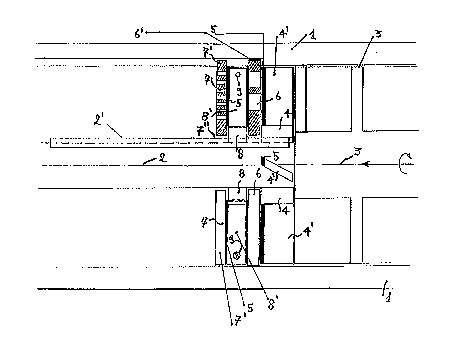
fig.l is a diagram showing the operation of a partially modified
.
mmcmg machlne
s figs. 2-3 are a side and front view of a traditional blade where
only the cutting edge has been modified, as shown in Fig. 1.
figs. 4-5 plan view and section of a new blade.
figs. 6-7-8-9, various views and sections of blades with variously
attached wear resi~t~nt f~cing~.
o figs. 10-1 1-12, side view, front view and section of a spoke of
the new star-shaped cutter.
fig 13, plan of a freely rotating ring cutter.
Figs. 14-15~ plan view and section ofthe new die desi~
With reference to the above figures, 1 indicates the stator of the m~c~.hine, 2
- 1S the drive sha~tjoined to the worm screw (3); 4 the fixed blade cutter (the
fixed blades are indicated with 4'), 5 the facing in wear resistant material
(stellite, t..ng~ten carbide, chrome cobalt steel); 6 the first perforated plate or
wide mesh die, joined in 6' to the stator (1); 7 the second tighter mesh
perforated plate in tool steel joined to the stator in 7'; 8 the star-shaped
20 cutter splined to the drive shaft (2) leader tongue 2'; 8' the removable toolsteel blade, with a stellite facing (S) fixed to the cutter (blade-holder) at 9.7" indicates the gap that necessarily forms between the blade and the die,
through which partially processed mince is conveyed which, recycled
through the so-called "gristle discharge" tube, may cause alterations in the
25 texture of the mince itself.

21 ~7939
-
In figs. 2-3 and figs. 4-5, 10 i~--lir~e the wear lesi~ small plate fixed laterally
on the blade holder (8) which contributes to relieve cutting edges (5) from
e~ce~,.,ive w(~ g p~es~,ure, keeping them sharp and thus plcvt;lllillg the dispersion
of met~llic lcsilues into the mince.
In figs. 5-9, 5' and 5" in-lir~te stellite or chrome cobalt facings having dirre~c,ll
shoulders than that of facing (5) to prevent the breaking or sepa,a~ion of the facing
m~teri~l itself.
In figs. 10-12, 8" in(1iç~t~s the back profile of a spoke of the star-shaped cutter
(8) facilit~ting the passage of the mince; and 8"' is the front prof~e l1.i~L~ g the
spoke itself so as to better with~t~n~ the deflection exerted by the higher speed
and stronger plcc,~,ule in the peripheral area. 5"' intlic~t~s the special L-shaped
facing fitted not on the blades (8') but directly on each spoke of the star-shaped
cutter (8). 10' in~ les the small p~s~,ur~ relieving plates, which in this version
areinceramics.
In fig. 13, 11 inrljcates the obstructing plate pr~tvellli~g the "short ch.;uili~g" of
the mince through the conduit (7"); 5"" in-lir~t~s the stellite or chrome cobaltsteel facing on plate (11) so as to make it lcsi~ ull to wear and as wide as theblades (5); 12 in~ir~tes the indentation on the cutter (8) which allows the plate
(11) to pel~ inside, while still rotating freely as the mince (water, fat), by
pel~ hlg through openillgs 13, supports it in the appropliate position in contact
with the dies on either side of the cutter.
In figs. 14-15, 14 intlir~t~s the first support disc for the actual die (15) which, due
to its !~ inl~s~" ~le~i~nrd to reduce load losses, would flex under strong pressure,
16 in-l;c~tes the large diameter c~ull~el ,unk perforations in 16' on the disk (14)
which force the mince only through small ~ mrter ~e~ro~lions (17) on the die
(15); 18 in-lir~trs the stellite or chrome cobalt facing which is also to be fitted on
the die.
In practice the application details, dimensions, materials, shape and other details
of the invention may still be altered without affecting the validity of this industrial

~ ' 21~7939
patent; indeed the invention thus ~çsignP11 may undergo several m~-lifir~tions and
variations con~illed within the concept of the invention. Ful~ lore all elemPn
may be replace~ by other ~ -ni-~lly equivalent el~mPnt~. -

Representative Drawing
A single figure which represents the drawing illustrating the invention.
Administrative Status

2024-08-01:As part of the Next Generation Patents (NGP) transition, the Canadian Patents Database (CPD) now contains a more detailed Event History, which replicates the Event Log of our new back-office solution.

Please note that "Inactive:" events refers to events no longer in use in our new back-office solution.

For a clearer understanding of the status of the application/patent presented on this page, the site Disclaimer , as well as the definitions for Patent , Event History , Maintenance Fee  and Payment History  should be consulted.

Event History

Description Date
Inactive: IPC from MCD 2006-03-12
Application Not Reinstated by Deadline 2005-06-17
Inactive: Dead - No reply to s.30(2) Rules requisition 2005-06-17
Deemed Abandoned - Failure to Respond to Maintenance Fee Notice 2004-10-15
Inactive: Abandoned - No reply to s.30(2) Rules requisition 2004-06-17
Inactive: S.30(2) Rules - Examiner requisition 2003-12-17
Amendment Received - Voluntary Amendment 2001-12-10
Inactive: Application prosecuted on TS as of Log entry date 2001-10-24
Letter Sent 2001-10-24
Inactive: Status info is complete as of Log entry date 2001-10-24
Request for Examination Requirements Determined Compliant 2001-09-26
All Requirements for Examination Determined Compliant 2001-09-26
Inactive: Cover page published 1999-09-30
Application Published (Open to Public Inspection) 1998-04-15

Abandonment History

Abandonment Date Reason Reinstatement Date
2004-10-15

Maintenance Fee

The last payment was received on 2003-09-17

Note : If the full payment has not been received on or before the date indicated, a further fee may be required which may be one of the following

  • the reinstatement fee;
  • the late payment fee; or
  • additional fee to reverse deemed expiry.

Patent fees are adjusted on the 1st of January every year. The amounts above are the current amounts if received by December 31 of the current year.
Please refer to the CIPO Patent Fees web page to see all current fee amounts.

Fee History

Fee Type Anniversary Year Due Date Paid Date
MF (application, 2nd anniv.) - small 02 1998-10-15 1998-09-29
MF (application, 3rd anniv.) - small 03 1999-10-15 1999-09-29
MF (application, 4th anniv.) - small 04 2000-10-16 2000-10-10
MF (application, 5th anniv.) - small 05 2001-10-15 2001-09-26
Request for examination - small 2001-09-26
MF (application, 6th anniv.) - small 06 2002-10-15 2002-10-01
MF (application, 7th anniv.) - small 07 2003-10-15 2003-09-17
Owners on Record

Note: Records showing the ownership history in alphabetical order.

Current Owners on Record
EVOLUTION S.R.L.
Past Owners on Record
MARCELLO QUADRANA
Past Owners that do not appear in the "Owners on Record" listing will appear in other documentation within the application.
Documents

To view selected files, please enter reCAPTCHA code :


To view images, click a link in the Document Description column (Temporarily unavailable). To download the documents, select one or more checkboxes in the first column and then click the "Download Selected in PDF format (Zip Archive)" or the "Download Selected as Single PDF" button.

List of published and non-published patent-specific documents on the CPD .

If you have any difficulty accessing content, you can call the Client Service Centre at 1-866-997-1936 or send them an e-mail at CIPO Client Service Centre.

({010=All Documents, 020=As Filed, 030=As Open to Public Inspection, 040=At Issuance, 050=Examination, 060=Incoming Correspondence, 070=Miscellaneous, 080=Outgoing Correspondence, 090=Payment})


Document
Description 
Date
(yyyy-mm-dd) 
Number of pages   Size of Image (KB) 
Representative drawing 1998-04-23 1 11
Description 1997-03-05 5 192
Abstract 1997-03-05 1 16
Claims 1997-03-05 2 54
Drawings 1997-03-05 6 115
Reminder of maintenance fee due 1998-06-15 1 111
Reminder - Request for Examination 2001-06-17 1 118
Acknowledgement of Request for Examination 2001-10-23 1 179
Courtesy - Abandonment Letter (R30(2)) 2004-08-25 1 167
Courtesy - Abandonment Letter (Maintenance Fee) 2004-12-12 1 176
Correspondence 1996-11-06 1 38