Note: Descriptions are shown in the official language in which they were submitted.
- 2 ~
INDIRECT-FIRED GAS TURBIN-E DUAL FUEh CELL POWER CYCLE
BAC~GRO~ND OF THE lN V~N-l~loN
The present invention relates generally to an integrated
fuel cell power plant, and more specifically to a combination of
cycles wherein a first fuel cell cycle tops an indirect-fired gas
turbine cycle and a second fuel cell cycle bottoms the gas
turbine cycle so that the cycles are thermally integrated in a
tandem operating arrangement. The United States Government has
rights in this invention pursuant to the employer-employee
relationship between the United States Department of Energy and
the inventors.
Gas turbines and fuel cells are well known mechanisms used
for the production of electric power. Gas turbine cycles and
fuel-cell cycles have each been previously bottomed with steam
turbine cycles for the co-generation of electric power. With
cycles employing a fuel cell, to pressurize the system,
compressors have been used to provide a stream of pressurized air
8 1 1 7
to the cathode of the fuel cell. Full advantage was not taken of
the pressurized air until assignee's patent 5,449,568 referenced
hereinbelow, wherein the air stream is heated with the exhaust
stream from a molten carbonate fuel cell bottoming a gas turbine.
To enhance fuel cell performance, carbon dioxide is added to the
air stream with the resulting mixture undergoing an electrochem-
ical reaction with fuel introduced at the anode of the fuel cell.
The fuel cell produces electrical energy and provides streams of
hot gases used for generating steam for a bottoming steam turbine
cycle that is coupled to a suitable electric generator.
A variation of such a combined cycle includes a fuel cell
bottomed with a gas turbine instead of the steam turbine cycle so
that residual heat energy in the cathode exhaust stream can be
directly extracted in the gas turbine for the production of
electric power. Such a system is described in assignee's U.S.
Patent No. 4,921,765 to Gmeindl et al which issued May 1! 1990
and is incorporated herein by reference thereto.
In another variation of gas turbine and fuel cell combined
cycles, a direct-fired gas turbine cycle is combined with a fuel
cell cycle for producing the hot gas stream used for driving the
gas turbine and thereby providing generation of electric power in
both the gas turbine cycle and the fuel cell cycle.
While these previously known combined cycles do provide for
the co-generation of electric power, these systems have not been
found to be capable of providing power conversion at high
efficiencies. The primary reason for this short-coming is that
- 2~ ~1 17
presently available fuel cells, such as molten carbonate fuel
cells as described in assignees aforementioned patent, can only
operate at pressures up to about six atmospheres so as to provide
turbine-driving gas streams at pressures less than required for
efficient operation of a gas turbine.
In an effort to improve the efficiency of these types of
combined cycles, an indirect-fired gas-turbine cycle was bottomed
with a molten carbonate fuel-cell (MCFC) cycle wherein the gas
turbine is operated at optimum pressure for efficient power
conversion. In this combined cycle arrangement, the gas turbine
is driven with indirectly heated air at a pressure appropriate
for efficient operation of the turbine, while the turbine
exhaust, which is at a pressure considerably less than-that at
the gas turbine inlet, is directly utilized in the fuel cell
cycle for the electrochemical reaction. Such a system is
described in assignees U.S. Patent No. 5,449,568 issued September
12, 1995 to Micheli et al and is incorporated herein by reference
thereto.
The system of the above referenced patent application
includes a compressor for providing a stream of compressed,
preheated air to the gas turbine. The compressed air is heated
in an indirect heat exchanger which is supplied with a stream of
heated gases from a combustor to which auxiliary fuel is supplied
along with the exhausts from the molten carbonate fuel cell
electrode chambers. The cathode chamber inlet of the fuel cell
is connected to the gas turbine exhaust to receive the stream of
2188~ 1 7
heated air discharged therefrom. The main fuel feed is supplied
to the anode chamber inlet of the fuel cell in the form of a
gaseous hydrocarbon fuel, such as fuel gas or natural gas. This
fuel is internally reformed into hydrogen and CO at the cell
anode for effecting the electrochemical reaction with the stream
of heated air supplied to the cathode thereof for the galvanic
production of electrical energy. The heated gases at the anode
and cathode exhausts are used to provide at least a portion of
the heat for the incoming pressurized air stream in the heat
exchanger.
To produce sufficient CO2 for the operation of the MCFC, a
portion of the hot gas stream from the cathode is combined in a
suitable catalytic reactor with the stream of hot gases,
including residual fuel values from the anode, for the production
of carbon dioxide. The carbon dioxide in the discharge stream of
hot gases from the catalytic reactor is separated in a CO2
separator and mixed with the hot air stream discharged from the
gas turbine and fed to the cathode reaction chamber of the fuel
cell.
The heat value from the stream of the heated gases that are
discharged from the heat exchanger can be further utilized for
power generation in various ways to further improve the system
efficiency. Also, by using the hot exhaust gases from the fuel
cell for partially heating the compressed air in the heat
exchanger of the gas turbine cycle, about 35-40~ of the heat
required to raise the compressed air at the inlet to a suitable
21881 1 7
gas turbine operating temperature, in the range of about 1600~ to
2600~F, is provided. This arrangement considerably reduces the
fuel requirement for heating the compressor discharge air to the
desired gas turbine inlet temperature.
Although many hardware limitations are overcome by using an
indirect-fired gas turbine cycle bottomed with a fuel cell cycle
as compared to a fuel cell cycle bottomed with a steam turbine
cycle, there remain inefficiencies in these types of combined
cycles in that additional fuel must be supplied to the system for
thermal powering and the requirement of an anode-to-cathode
recycle system to produce CO2 required for the molten carbonate
fuel cell cathode reaction. Thus, there is a need for a fuel
cell integrated power gèneration system with improved thermal
integration and higher operating efficiencies.
S~MM~Y OF THE lN V~N'l'lON
In view of the above need, it is an object of this invention
to provide an improved fuel cell integrated power generation
system.
Another object of this invention is to provide an improved
fuel cell integrated power generation system which requires no
supplemental fuel for thermal powering.
Further, it is an object of this invention to provide an
improved thermally integrated power generation system as in the
above object in which a turbine cycle is topped with a solid
oxide fuel cell (SOFC) and bottomed with an MCFC.
- 21~81 17
Yet another object of this invention is to provide an
improved fuel cell integrated power generation system as in the
above object in which the CO2 necessary for operation of the MCFC
is generated in the SOFC topping the turbine cycle and cascaded
through the system to the MCFC cathode.
In summary, this invention relates to a fuel cell and gas
turbine combined cycle system which includes dual fuel cell
cycles combined with a gas turbine cycle wherein a first fuel
cell cycle tops the turbine cycle and is used to produce CO2 for
a second fuel cell cycle which bottoms the turbine and is
opèrated at essentially atmospheric pressure. The first fuel
cell cycle is operated at a pressure in the range of from about 6
to 15 atms. Compressed air is heated in an indirect heat
exchanger and supplied to the first fuel cell cycle along with a
pressurized fuel stream. The heat exchanger is supplied with a
stream of heated gases from a low pressure combustor fueled by
the excess fuel effluent from the second fuel cell cycle. The
effluents from the first fuel cell cycle are fed to a high
pressure combustor in which the excess fuel is burned to raise
the pressurized gas stream to the gas turbine to the desired
temperature. The turbine exhaust is fed to the low pressure
combustor wherein it is used to burn the excess fuel effluent
from the anode of the second fuel cell cycle to provide heat for
the input air indirect heat exchanger.
In addition, the heat energy of the effluent from the
cathode of the second fuel cell cycle may be utilized in a heat
21~B~ 17
-
recovery steam generator (HRSG). The HRSG may be used also to
provide the necessary water in the form of steam to the fuel cell
cycles to promote internal reforming of CH4 fuel to hydrogen.
In a preferred arrangement, a solid oxide fuel cell (SOFC)
is uniquely positioned and thermally integrated with the system
to not only produce power under desirable conditions, but also to
supply the required CO2 for the efficient operation of the
downstream fuel cell which is preferably a molten carbonate fuel
cell (MCFC). The MCFC is more efficient in converting natural
gas to electric power than either the SOFC or the gas turbine,
but requires a CO2 source.
Using accepted systems simulations programs, this preferred
dual fuel cell and gas turbine combined cycle has been shown to
provide a thermodynamically optimized system for electrical power
production due to the power generating subsystems being operated
in series or tandem and not in parallel. In this case the unused
power from the first generating unit, the SOFC, cascades into the
second unit, the gas turbine, and the second unit into the third,
the MCFC. Since the SOFC operates best at about 2000~F, it has
been found to be ideal for the topping position, while the MCFC
operates optimally at about 1000~F and hence as a bottomer to the
turbine.
Further, the cycle efficiency of this preferred arrangement
is greatly enhanced by adding all of the heat energy obtained
from the unreacted hydrogen and carbon monoxide effluent from the
fuel cell anode streams to the gas stream ahead of the turbine
218~1 17
inlet. This arrangement is a form of recuperation, that is by
recycling this energy back to the turbine, the power output of
the turbine is increased. Detailed system analyses have shown
that this combustor approach is essential to achieving high cycle
S efficiency. In all known MCFC combined cycles, the unreacted
fuel from the anode is recycled back from a combustor to the
cathode to provide the CO2 needed. Although these anode-to-
cathode recycle streams provide the necessary CO2, they defeat
the ability to achieve a high efficiency because the thermal
streams are at the wrong temperature for proper cascading.
This thermal tandem arrangement may be optimized to provide
a maximized efficiency which has been determined to be in the
range of 72-74~ (LHV) net. The turbine size may be selected
either to optimize the efficiency or to reduce the system costs,
or any combination in between. Systems analyses include about 6
percentage points in losses for pressure drop, heat losses and DC
to AC power conversion.
Other objects and many of the attendant advantages of the
present invention will become evident to those skilled in the art
from the following detailed description taken in conjunction with
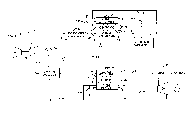
the drawing wherein the single figure is a schematic block
diagram of an integrated dual fuel cell and gas turbine power
generation system according to the present invention.
DETAIhED DESCRIPTION OF THE lNv~N~lloN
As pointed out above and shown in the figure, the preferred
fuel cell types used in the combined dual fuel cell and indirect-
21i ~1 1 7
fired gas turbine cycle of the present invention include a solid
oxide fuel cell (SOFC) 5 as the topping unit and a molten
carbonate fuel cell (MCFC) 7 as a bottoming unit to the gas
turbine 9. Since these fuel cells have been adequately
developed, only the main components of these fuel cells, the
anode, the cathode and electrolyte, will be illustrated here.
Additional information regarding the details of these types of
fuel cells may be had by referring to the "Fuel Cells Handbook,"
January 1994 issued by DOF/METC-94-1006. This reference being
incorporated herein by reference thereto.
Referring to the illustrations in the Figure, the SOFC 5
includes two porous electrodes 11 and 13 bonded to a solid oxide
ceramic electrolyte 15 disposed between them to form a
selectively-permeable barrier. The fuel, in the form of
hydrogen, is supplied to the anode electrode 11 side of the
barrier through an anode gas flow channel 17 while an oxidant, in
this case air, is supplied to the cathode electrode 13 side
thereof through a cathode gas flow channel 19. Most reactants
cannot pass through the barrier, but oxygen ions can flow through
the solid oxide lattice. The electrodes are formed of porous
electrically conductive metallic or semiconducting ceramic
materials. Typically, the fuel electrode (anode 11) is formed
from nickel-zirconia cermet, or the like, the air electrode
(cathode 13) is formed from strontium-doped lanthanum manganite,
or the like, and the solid oxide electrolyte 15 is formed of
yttria-stabilized zirconia, or the like. The cells are typically
2la~1 17
.
made in a coaxial cylindrical array and a number of cells are
electrically connected in series through a load 21 to form a
stack. The SOFC is operated at a temperature in the range of
from about 1400~ to 2300~F.
Suitable fuels include hydrogen and simple hydrocarbons such
as methane CH4. In this application, CH4 is supplied via fuel
input line 23 to the anode gas channel 17 of the fuel cell and is
internally reformed within this ~h~nn~l by reacting the CH4 with
water (i.e., steam) in the presence of the nickel in the anode,
which acts as a catalyst. This reaction provides hydrogen for
the electrochemical reaction which produces hot streams of
reaction gases at the respective electrode gas flow channels.
CO2 is produced as a result of this process which is supplied to
the MCFC cathode as will be described hereinbelow to provide most
of the additional CO2 required for operation of the MCFC 7. The
r~m~;n;ng portion being supplied by combustors in the system.
Typically, a MCFC requires an oxidant containing a ratio of CO2
to ~2 Of about 2:1 for the stoichiometry of the electrochemical
reaction. Since air does not have this ratio, additional CO2
must be added to the cathode reaction chamber for the cell to
operate efficiently.
Generally, the MCFC 7 includes an anode electrode 24 formed
of porous nickel or the like separated from a cathode electrode
25 of porous nickel oxide or the like by a molten electrolyte 26
formed of an alkali metal carbonate and mixtures thereof
contained within a porous ceramic matrix, commonly made of
21881 17
lithium aluminate (LiAlO2). The MCFC cells are usually made in a
layered array and a number of cells are electrically connected in
series through a load 29 to form a stack.
With the electrolyte heated to a molten state, a fuel such
as hydrogen, derived from fuel gas or natural gas through
internal reforming, as described above, at the anode undergoes an
electricity-producing electrochemical reaction with oxygen at the
cathode. This electrochemical reaction also produces hot streams
of reaction gases at the anode and cathode gas channels which are
utilized in the combined cycle system as will be described. The
MCFC is operated at a temperature in the range of from about
1000~ to 1150~F.
The indirect-fired gas turbine 9 is coupled to a compressor
33 by a drive shaft 34 and to an electric generator 36. The
compressor may be of any suitable type capable of receiving a
stream of air 35 at the inlet thereof and compressing this stream
of air to a pressure in the range of about 6 to 25 atms and to a
temperature in the range of about 300~ to 800~F This stream of
compressed air is passed through conduit 37 into a heat exchanger
39 wherein the compressed air stream is indirectly heated by a
hot gas stream from a low pressure combustor 41 through a conduit
43 connecting the output of the combustor to the heat transfer
element input of the heat exchanger 39. Although the flows as
illustrated in the drawing are co-current, the heat exchange
means is preferably counter-current or cross-current-. The
compressed air is heated to a temperature in the range of about
8111
1500~ to 2500~F, preferably about 2000~F. The heat exchanger 39
may be of any suitable type capable of heating the compressed air
to the desired temperature range. Preferably, the heat exchanger
39 is formed of high temperature metal and/or a ceramic material
due to the relatively high temperature requirements. The hot
compressed air stream discharged from the heat exchanger 39 is
conveyed through conduit 45 to the cathode gas channel 19 of the
SOFC 5.
Along with the heated air supplied to the cathode gas
channel 19 of SOFC 5, the fuel CH4 is introduced through a pump
23 to the anode gas channel 17 at a presSure consistent with the
operating pressure of the SOFC, in this case about 5-20 atms.
The CH4 reacts with water in the form of steam, which may be
introduced into the channel in various ways as will be described
in one example herein below, in the presence of a catalyst such
as nickel present in the anode 11 structure to produce the
hydrogen required for the anode reaction and CO2.
Alternatively, the fuel may be reheated by passing the fuel
stream through a heat exchanger heated by the anode exhaust
stream.
The hydrogen reacts electrochemically with oxygen supplied
to the cathode gas channel 19 in the preheated, compressed air
stream entering the cathode channel. This electrochemical
reaction produces both electricity and water. At the operating
temperature of the cell, in the range of from about 1400~ to
2300~ F, the water is quickly converted to steam which aids in
~Z 11 88 1 1 7
-
reforming of the CH4 within the anode channel. However, since
neither all of the H2 at the anode nor all of the ~2 at the
cathode is reacted, the excess flows out of the anode and cathode
gas channels along with the water and CO2 in the anode stream and
~ the remaining components of the air stream in the cathode stream.
The effluents from the anode and cathode gas flow channels
17 and 19, respectively, of the SOFC are conveyed to a high
pressure combustor 47 via conduits 49 and 51, respectively. The
high pressure combustor operating at the SOFC 5 operating
pressure provides additional heat to the pressurized hot gas
stream being fed to the turbine 9 inlet via conduit 53 connected
between the output of the combustor 47 and the turbine inlet.
The high pressure combustor may take various forms in which the
unreacted H2 and CO from the SOFC 5 anode channel 17 is combusted
in the presence Of ~2 from the cathode channel 19 to further heat
the hot gas stream. This further heated hot gas at a temperature
in the range of about 1800~ to 2300~F, preferably about 2200~F,
is fed to the turbine 9 at a pressure of about 5 to 20 atms,
preferably about 10 atms to operate the turbine and in turn
compress the input air stream and generate electricity in the
generator 36 The operating gas temperature for the turbine may
be altered by changing the amount of fuel fed to the SOFC anode.
It may be required to add excess fuel and cut back on the fuel
utilization of the first fuel cell , thus providing excess fuel
to the high pressure combustor and raise the temperature of the
gases from the combustor to the gas turbine. This is not
21,~iil7
necessarily a major detriment to the cycle efficiency because the
turbine power will increase as well as the efficiency
contribution of the heat engine component to the overall cycle.
The exhaust gas from the gas turbine 9 is at a temperature
in the range of about 600~ to 1300~F, preferably about 1000~F,
and at essentially ambient pressure. This exhaust gas from the
turbine is fed via conduit 55 to the low pressure combustor 41
together with the MCFC 7 anode channel exhaust via conduit 57.
The unreacted H2 and CO from the MCFC anode exhaust is combusted
in the low pressure combustor 41 in the presence of the rem~;n'ng
oxygen available in the turbine exhaust stream 55. This low
pressure combustor produces a hot gas stream rich in CO2 cascaded
through the system from the SOFC 5 and the high pressure
combustor 47. The gas stream is further heated to a temperature
in the range of about 1100~ to 1400~F, but preferably less than
1350~F. This heated gas stream passes into the heat exchanger 39
via conduit 43, as described above, and out through conduit 59 to
the cathode gas channel 28 of the MCFC 7. The temperature of the
gas stream from the heat exchanger is in the range of about 1000~
to 1150~F, preferably 1100~F, and at a pressure in the range of
about 1 to 3 atms. The temperature of this gas stream may be
varied by varying the fuel supplied to the MCFC anode 27 or by
varying the heat exchange path through the heat exchanger 39, as
shown in the drawing.
As the heated air, enriched with CO2, enters the cathode gas
channel 28 of the MCFC 7, a gaseous fuel such as fuel gas or
14
- 2~18~1 17
natural gas is concurrently conveyed into the anode gas channel
27 of the fuel cell via conduit 61. This gaseous fuel is
preferably preheated to a temperature generally corresponding to
that of the gas stream delivered to the cathode gas channel 28 so
as to assure the liquification of the carbonate electrolyte and
thereafter facilitating the continuing electrochemical reaction
within the fuel cell 7. The preheating of the fuel to reforming
temperature may be accomplished by recycling a portion of the
anode exhaust stream to the anode fuel inlet via line 63
With the heated streams of fuel and the CO2-enriched air
stream delivered to the fuel cell 7, the electrochemical reaction
proceeds as described in assignee's aforementioned patent to
generate electrical energy while producing reaction gases formed
primarily of CO2 and water at the anode and unreacted CO2, water
and vitiated air at the cathode. Typically this gas stream
contains about 14~ CO2, 3~ ~2l and 11~ H2O, with N2 making up the
primarily the r~m~ning portion. The ration of CO2 to ~2 should
be greater than 2 throughout the cathode flow of the fuel cell.
Only the MCFC is operated at vitiated ~2 conditions. All of the
oxygen supply for the system is provided through the input air
stream which contains approximately 23~ ~2 by Wt. About 12 to
16 ~ by Wt. is consumed by the SOFC 5, while only about 1 to 3
by Wt. is consumed by each of the combustors 41 and 47, leaving
an ~2 content of about 5 to 7 ~ by Wt. in the gas stream entering
the cathode of the MCFC 7. Approximately, 2 to 3 ~ by Wt. of ~2
218~1 ~7
is consumed in the MCFC, leaving approximately 3~ by Wt. in the
exhaust stream from the MCFC cathode.
As shown in the figure, the MCFC.7 cathode exhaust gases,
which are at a temperature in the range of about 1000~ to 1300~F,
usually about 150~-200~F higher than the temperature of the gas
and fuel delivered to the fuel cell 7, may be discharged to the
atmosphere, recycled to the low pressure combustor 41, or
preferably discharged from the fuel cell via conduit 65 to a
utilization cycle such as the heat recovery steam generator
(HRSG) 67 cycle shown in the drawing. The hot gas stream 65 is
fed into a boiler or the like, not shown, of the HRSG for
extracting residual heat energy from these gases while producing
steam for use in a steam turbine 69 for the generation of
electrical power by a generator 71. Further, the HRSG may be
used to provide water, in the form of steam, to the fuel
electrodes (anodes) of both fuel cells 5 and 7 via conduits 73
and 75, respectively, at the separate cell operating
temperatures, as described above for reforming the CH4 to H2.
By employing the dual fuel cell and indirect-heated gas
turbine combination and the steam turbine cycle, as described
above, the resulting electrical power generation sources provide
an increase in the overall cycle efficiency of about 6~ over any
known combination of a fuel-cell cycle bottomed or topped by a
gas turbine cycle or by a direct-heated gas turbine cycle
employing a fuel cell cycle.
16
2 1 ~8~ 1 7
In another modification of the present invention, the MCFC 7
may be operated at an intermediate pressure greater than
atmospheric, such as in the order of about two to five
atmospheres, the cathode exhaust stream will be at a pressure
adequate to drive a low-pressure turbine under pressurized
conditions. This will reduce the size and cost of the MCFC. The
low-pressure turbine exhaust can be used to heat water in a
boiler to boiling temperature with the steam generated at an
intermediate pressure of the low pressure turbine. This converts
the gas turbine into a low pressure power generator and
effectively eliminates the need of a steam turbine system
following the MCFC. While the cycle efficiency is not as high as
in the preferred embodiment described above, this approach
reduces the balance of plant significantly and serves to reduce
system costs.
It will be seen that the combined cycle of an indirect-fired
gas turbine cycle topped and bottomed with a fuel cell cycle and
further employing a steam turbine cycle together provide a
significant improvement in combined cycle technology which
operates at a relatively high efficiency as compared to
previously known combined cycles such as described above. Also,
by cascading the air flow through the system without shunting any
of the pressurized air that runs the turbine to burn the excess
hydrogen from the fuel cells, more power and hence higher
efficiency is achieved.