Note: Descriptions are shown in the official language in which they were submitted.
'. 2188177
TITLE
"A sealed beverage package and a method of forming
such a package"
TECHNICAL FIELD & BACRGROUND ART
The present invention relates to a sealed beverage
package and a method of forming such a package. More
particularly it concerns a sealed package of the kind
containing beverage having gas in solution and within which
package is located a froth developing means, typically a
lo hollow insert containing gas under pressure which, upon
opening of the package and in response to a pressure
differential developed thereby, causes fluid in the form of
a gas or a liquid and gas, to be ejected from the insert to
cause, or assist in, the formation of a head of froth on
the beverage by the evolution of gas dissolved in the
beverage. Froth developing means are now well known in
the art and can take many forms of structure and operation
and an example of which is discussed in our Patent
Specification G.B.-A-2,183,592.
Beverage packages made in accordance with the
preferred embodiment of our aforementioned British Patent
Specification have met with considerable commercial success
where, as with many other froth developing means, the
insert is located at or towards the bottom of a container
and retained as a press or interference fit with an
upstanding side wall of the container. However, for some
beverage packages it has been found desirable to locate and
retain the froth developing means other than as
aforementioned, for example to facilitate fitting of the
insert within a particular form of container that is
utilised and to locate the froth developing means at what
is considered to be a preferred position for effecting
froth development in the particular beverage that is
2 ~ 88 1 77
-
packaged. For example, our Patent Specification EP-A-0
518 522 discloses the location of a hollow insert within a
narrow necked bottle and retained by an upward extension of
the insert frictionally engaging with the narrowed top part
of the bottle.
Our Patent Specification G.B.-A-1,266,351 discloses a
sealed beverage package in which the froth developing means
is carried within a container having an openable top by a
removable closure or cap for that top. The carriage of
the froth developing means by the removable closure of the
container is particularly convenient for some beverage
packaging lines, for example where the container is in the
form of a narrow necked open topped bottle, and it is an
object of the present invention to provide an improved
sealed beverage package and a method of forming such a
package where the froth developing means is carried by a
closure for an openable top of the package.
~TATEMENT8 OF I~v~ ON ~ ADVANTAGES
According to the present invention there-is provided
a sealed beverage package comprising a container having an
openable top and a closure part for said top; the
container containing beverage which has gas in solution and
forms a headspace that is at a pressure greater than
atmospheric; froth developing means comprising an insert
part carried within the container by said closure, said
froth developing means reacting when the top of the
container is opened and in response to a pressure
differential developed thereby to cause gas to be liberated
from solution in the beverage for froth development, and
wherein the insert part is carried by the closure part
through a coupling which comprises a spigot on one of said
parts engaging in a socket on the other of said parts, said
spigot having a head and said socket engaging over the head
2 1 88~ 7i7
to retain it from withdrawal from the socket and to capture
the head in the event of its separation from the part on
which it is located.
Further according to the present invention there is
provided a method of forming a sealed beverage package as
specified in the immediately preceding paragraph which
comprises providing one of a socket and spigot on a closure
part; providing the other of said socket and spigot on an
insert part of froth developing means; press fitting the
socket to the spigot to form a coupling in which the socket
engages over a head of the spigot to retain the head from
withdrawal from the socket and to capture the head in the
socket in the event of the head becoming separated from the
part on which it is located and so that the insert part is
carried through the coupling by the closure part; moving
the insert part into an open topped container through the
open top thereof and which container contains beverage
having gas in solution and sealing the closure part to the
container to close the open top whilst providing pressure
greater than atmospheric in a headspace formed by the
beverage in the container.
By the present invention it is intended that the
socket and spigot engagement between the closure part and
the insert part provides a coupling which may be regarded
as inseparable other than for when excessive separation
forces are applied to the coupling (to the extent that such
separation forces would result in identifiable damage being
caused to components in the package, particularly the
coupling, the insert part or the closure part).
Commercially it is important that the froth developing
means does not separate from the closure part which carries
it to become a free body within the beverage; whilst such
separation may not hinder the reaction of the froth
2l88l~
-
developing means when the package is opened, the free body
may be dispensed along with the beverage with undesirable
consequences.
Usually the froth developing means will comprise a
hollow insert part which contains at least gas at a
pressure greater than atmospheric (and may contain both
such gas and liquid/beverage) and have a restricted
aperture so that when the top of the container is opened
for the headspace to communicate with atmosphere, the
pressure differential which develops causes fluid (gas or
gas and liquid) in the insert to be ejected through the
restricted aperture into the beverage for the development
of a head of froth on the beverage by the evolution of gas
from solution in the beverage. During the opening of the
package, typically by removal of the closure part as in the
case of a crown-type cap, it is possible for the package to
be tilted and/or the hollow insert to be tilted to an
extent where the restricted aperture is exposed from the
beverage thereby reducing or negating the froth developing
characteristics. To alleviate this possibility it is
preferred that the insert part is carried by the coupling
pendulously relative to the closure part. To achieve this
the head of the spigot may be a loose fit within the socket
whilst clearance is provided between a neck of the spigot
on which the head is carried and the socket to permit the
insert part to hang from, and swing relative to, the
closure part so that if the container is tilted (within
reason) from the vertical, a vertical orientation can be
maintained for the insert to retain the restricted aperture
submerged.
For convenience of assembly of the froth developing
means with the closure part, typically in association with
a packaging line where the open topped containers move
2188177
towards a filling and sealing station, it is preferred that
the head is simply press fitted to the socket to snap
engage therewith. With this in mind, at least one of the
head and socket may be provided with a tapered lead-in
surface for facilitating the location of the head in the
socket and the press fitting engagement. To ensure that
the head of the spigot is captured by the socket, such head
may have a barb which engages with a shoulder of the socket
to restrain withdrawl of the head from the socket.
It is not unknown for purchasers of beverage packages
which include froth developing means to seek compensation
for alleged damage caused by the froth developing means or
portions thereof becoming loose or breaking free within the
container. With the package of the present invention it
will be usual, but not essential, for the closure part to
be completely removed from the container on opening and to
carry with it the froth developing means thereby exposing
such means to the user. It is possible therefore for
damage to be inflicted purposely on the froth developing
means with the intention of seeking compensation with an
unjustified claim. With this in mind it is preferred that
the or a neck on which the head of the spigot is located is
frangible so that the head will break off and be retained
in the socket in response to a manual bending force applied
between the insert part and the closure part. Obviously
where a claim for compensation is made the components of
the beverage package must be available for inspection and
if the neck is broken purposely as aforementioned (as
compared with such breakage as may occur naturally
following normal packaging and handling), this will become
apparent by stress form analysis of the break surfaces
presented on the neck, particularly by the material of the
head that is retained in the socket. Alternatively, or
27~8l 77
-
in addition, the neck on which the head is located may be
provided with a weakened region at which the head can be
broken off to be retained in the socket in response to a
manual bending force applied between the insert part and
the closure part so that following such a break the head
captured by the socket can again be subjected to stress
form analysis.
Either or both of the socket and spigot will usually
be formed as a plastics moulding. Typically the insert
part will be formed as a plastics moulding and the socket
or spigot on that part is conveniently moulded integral
therewith. The present invention was primarily, but not
essentially, developed for a beverage package formed with
an open topped bottle having a closure part which carries
a sealant for effecting a seal between that part and the
bottle. This sealant is usually thermo-formed, hot plate
welded or glued on to the closure part and may itself be
moulded to present the socket or spigot. However,
sealant materials will usually be too resilient to define
and serve for the socket or spigot~ particularly the
latter. It is preferred therefore that when the closure
part comprises a sealant as aforementioned, the socket or
spigot on the closure part is formed as a plastics moulding
and that moulding is captured on the closure part by the
sealant.
Preferably the spigot is on the insert part and the
socket is on the closure part, this is particularly
convenient for open topped bottles where the closure part
is in the form of a crown cap but it will be realised that
the reverse arrangement can be employed. Furthermore,
whilst the closure part and froth developing means carried
thereby will usually be completely removed from the
container on opening of the container for dispensing the
2 1 8 8 1 7 7
beverage, such complete removal is not essential, for
example where the closure part may be partially removed or
an opening otherwise formed in the beverage package for
dispensing purposes.
DRAWINGS
One embodiment of a sealed beverage package
constructed in accordance with the present invention will
now be described, by way of example only, with reference to
the accompanying illustrative drawings in which:-
Figure 1 is a section through the package showing the
coupling between the closure cap and a hollow insert of the
froth developing means, and
Figure 2 is an exploded view, in section, showing the
closure cap and components for the coupling and the hollow
insert comprised in the package of Figure 1.
DETAILED DESCRIPTION OF DRAWINGS
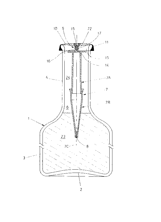
The sealed beverage package is formed with a container
1 which consists of a conventionally shaped bottle, usually
of glass, ceramic or plastics having a base 2 and an
upwardly extending cylindrical side wall 3 that converges
to a neck 4 which defines an open top 5 for a chamber 6
within the bottle.
Located within the chamber 6 is a hollow plastics
insert 7 which contains gas under pressure and has a
restricted aperture 8 through which gas and/or
liquid/beverage in the insert 7 is to be ejected for the
purpose of developing a head of froth on beverage 23
contained in the chamber 6.
The insert 7 is carried through a coupling 9 by a
closure 10 for the open top 5. The closure is in the form
of a crown cap 10 which is retained in conventional manner
by crimping over an external annular lip 11 at the mouth of
the bottle neck 4 so that the crown cap 10 can be removed
2188177
with the aid of a bottle opener or by twisting.
The hollow insert 7 is conveniently formed as a two
part moulding 7A, 7B of which an upper part 7A has an
external annular rib 12 and a lower part 7B has an internal
annular groove 13 and includes, at its bottom end, the
aperture 8. The insert 7 is assembled by snap fitting the
rib 12 within the groove 13 and heat sealing the parts 7A
and 7B together to form a chamber in the insert which is
sealed other than for the aperture 8. The insert 7 is
elongated along an axis 7C for convenience of fitting co-
axially within the neck 4 of the bottle and to provide
clearance with the neck.
The upper end of the insert part 7A has integrally
moulded therewith an upwardly extending spigot 14 of the
coupling 9. The spigot 14 is co-axial with the axis 7C
and has a barbed head 15 carried on a neck 16. Also
forming part of the coupling 9 is a plastics moulded socket
17 of tubular form and which has an internal shoulder 18
and an external flange 19. A tapered mouth 20 of the
socket provides a lead-in surface to a necked region 18A
formed in the bore of the socket adjacent to the shoulder
18. The socket 17 is secured to the underside of the cap
10 substantially centrally thereof. Conventionally crown
caps 10, particularly when of metal, are provided on their
underside face with a sealant 22 (Figure 1) which forms a
seal between the cap and the lip 11 during the crimping
operation. Conveniently therefore the socket 17 is
secured to the underside of the cap 10 by the sealant 22 as
the latter is thermo formed, welded or glued on the cap to
capture the flange 19. It will be appreciated however
that alternative techniques may be employed for securing
the socket 17 on the underside of the cap 10, for example
by adhesive or welding and it is also possible for the
2188177
~,
socket 17 to be formed integral with the cap 10 or with the
sealant 22.
In the packaging process the insert 7 assembled from
the parts 7A and 7B heat seal together as aforementioned
will usually be supplied separately from the cap 10 having
the socket 17 already secured thereto by the sealant 22.
Whilst an empty bottle 1 in an upstanding condition is
moving along a bottle filling line (on which it is charged
with an appropriate volume of beverage 23 containing gas in
solution) the cap 10/socket 17 assembly and the insert 7
are conveniently moving parallel with the bottle and being
connected together through the coupling 9. For this
connection the head 15 of the spigot is press fitted co-
axially into the socket 17 through the mouth 20 and necked
region 18A thereof so that its barbs snap engage over the
shoulder 18 and thereby the head is captured in the socket
and prevented from being withdrawn. The barbed head 15 is
conveniently tapered to provide a lead-in surface which co-
operates with the lead-in surface 20 of the socket to
facilitate the engagement of the coupling co-axially. The
coupling 9 that is formed may be relatively rigid.
Preferably however the head 15 is a loose fit within the
socket 17 whilst a clearance is provided between the necked
region 18A in the bore of the socket 17 and the neck 16 of
the spigot 14 so that the insert 7 will hang from the cap
10 in pendulous manner (whereby the insert 7 is permitted
to swing through the coupling 9 relative to the cap 10).
It will be noted that the tapered lead-in surface 20 also
provides clearance to permit for the aforementioned
swinging movement.
Following coupling of the insert 7 to the cap 10 and
charging of the bottle chamber 6 with the required beverage
23 (containing gas such as carbon dioxide and/or nitrogen
2188177
-
in solution) to form a headspace 24, the insert 7 is
located co-axially within the neck 4. The beverage 23
will usually be alcoholic such as fermented stout, ale,
lager or cider or non-alcoholic such as so-called soft
drinks. The headspace 24 is pressurised conveniently by
liquid nitrogen dosing or within a pressure chamber and the
open top 5 of the bottle sealed by crimping the crown or
screw cap to the lip 11 as aforementioned to form the
beverage package with its headspace at pressure greater
than atmospheric.
The hollow insert 7 will contain gas under pressure
which is maintained by the pressurisation of the headspace
24. Upon opening of the container 1 by removal of the cap
10, the headspace 24 reduces to atmospheric pressure and,
in known manner, a pressure differential results which
causes pressurised gas and/or liquid in the insert 7 to be
ejected therefrom through the restricted aperture 8 for the
development of a head of froth on the beverage 23 (for
example in the manner discussed in our Patent Specification
G.B.-A-2,183,592).
During opening of the bottle it is most desirable that
the aperture 8 is submerged in the beverage 23 for optimum
froth development. It is possible that during removal of
the cap 10 the bottle will be tilted from an upright
condition. With a rigid coupling between the cap 10 and
the insert 7, this tilting can result in the aperture 8
being exposed from the beverage or have its depths of
submersion reduced to an extent that the froth development
characteristics are less effective. However, by
pendulously mounting the insert 7 through the coupling 9 as
aforementioned, if the bottle 1 is tilted (within reason)
from its upright condition, the insert 7 can swing on the
cap 10 to maintain an upright condition and alleviate the
2 1 8~ 1 77
likelihood of the aperture 8 becoming exposed from, or too
shallow in, the beverage 23.
In the present embodiment it is intended that the cap
10 together with the insert 7 carried thereby is removed
fully from the bottle 1 for dispensing of the beverage
after the initiation of the froth development. Following
exposure of the insert 7 from the bottle it is possible
that the insert 7 may be purposely broken off from the cap
10 with the intention of making an unjustified claim for
compensation as a result of damage allegedly caused by the
insert being a free body within the beverage 23 during its
dispersion and consumption. With this in mind it is
preferred that the neck 16 of the spigot 14 is frangible
and/or has a weakened region whereby the barbed head 15 can
break off from the insert 7 in response to a manual bending
force applied between the insert 7 and the cap 10. Upon
such breakage the head 15 is captured to be retained within
the socket 17. In the event of a claim for damage as
aforementioned it is reasonable to expect the components of
the bottle package to be returned to the manufacturer for
examination, particularly the cap 10 or the insert 7 and
preferably both. By stress form analysis of the break
surface on the head 15 captured in the socket 17 it will be
possible to determine whether the breakage occurred as a
result of natural usage and faulty manufacture or was
inflicted purposely. Similar comments apply to the break
surface presented on the neck 16.
It will be appreciated that the beverage package can
have the coupling reversed by forming the socket 17
integral with the insert 7 and securing the spigot 14 to
the underside of the cap 10.