Language selection

Search

Patent 2188393 Summary

Third-party information liability

Some of the information on this Web page has been provided by external sources. The Government of Canada is not responsible for the accuracy, reliability or currency of the information supplied by external sources. Users wishing to rely upon this information should consult directly with the source of the information. Content provided by external sources is not subject to official languages, privacy and accessibility requirements.

Claims and Abstract availability

Any discrepancies in the text and image of the Claims and Abstract are due to differing posting times. Text of the Claims and Abstract are posted:

  • At the time the application is open to public inspection;
  • At the time of issue of the patent (grant).
(12) Patent: (11) CA 2188393
(54) English Title: A DEVICE FOR CONTROLLING A SPACECRAFT BY GATING GAS VIA A MOVING NOZZLE
(54) French Title: DISPOSITIF DE COMMANDE D'UN ENGIN SPATIAL PAR TRANSMISSION SELECTIVE DE GAZ VIA UN AJUTAGE MOBILE
Status: Expired and beyond the Period of Reversal
Bibliographic Data
(51) International Patent Classification (IPC):
  • B64G 01/26 (2006.01)
  • F02K 09/86 (2006.01)
(72) Inventors :
  • DUMORTIER, ANDRE (France)
  • FAGET, JEAN-GABRIEL (France)
(73) Owners :
  • SOCIETE NATIONALE D'ETUDE ET DE CONSTRUCTION DE MOTEURS D'AVIATION "SNECMA"
  • SOCIETE EUROPEENNE DE PROPULSION
(71) Applicants :
  • SOCIETE NATIONALE D'ETUDE ET DE CONSTRUCTION DE MOTEURS D'AVIATION "SNECMA" (France)
  • SOCIETE EUROPEENNE DE PROPULSION (France)
(74) Agent: MCCARTHY TETRAULT LLP
(74) Associate agent:
(45) Issued: 2002-02-19
(22) Filed Date: 1996-10-21
(41) Open to Public Inspection: 1997-04-21
Examination requested: 2000-09-08
Availability of licence: N/A
Dedicated to the Public: N/A
(25) Language of filing: English

Patent Cooperation Treaty (PCT): No

(30) Application Priority Data:
Application No. Country/Territory Date
95 12362 (France) 1995-10-20

Abstracts

English Abstract


A device for controlling a spacecraft by gating gas,
the device comprising a nozzle (20), a gas feed duct
(12), a gate having a seat (22) and a plunger (18)
interposed between the feed duct and the nozzle, and
control means (40) for opening and closing the gate in
order to put the feed duct selectively into communication
with the nozzle. The seat (22) of the gate is secured to
the nozzle (20) and the nozzle is movable such that the
gate is opened and closed by displacement of the nozzle,
which displacement is driven directly by the hot gas,
without calling on an auxiliary fluid.


Claims

Note: Claims are shown in the official language in which they were submitted.

WHAT WE CLAIM IS:
1. A device for controlling a spacecraft by gating gas, said device
comprising:
a nozzle having a gate seat integrally formed therewith;
a hot gas feed duct in selective communication with said nozzle;
a plunger constituting with said seat a gate interposed between said hot gas
feed duct and said nozzle; and
control means including a pilot valve for controlling the opening and the
closing of said gate in order to selectively open or close communication
between
said hot gas feed duct and said nozzle, wherein said nozzle is integrally
formed with
a movable piston housed in a cylinder and divides the inner volume of the
cylinder
into a first chamber permanently connected to said hot gas feed duct, and a
second
chamber in communication with said first chamber and connected to said pilot
valve
via an exhaust duct opening into the second chamber, wherein said plunger is
fixed
with respect to said cylinder, and wherein the opening and closing of said
gate is
caused by hot gas admitted through said hot gas feed duct and acting directly
on said
piston to move said nozzle away or towards said plunger under the control of
said
pilot valve.
2. The device according to claim 1, wherein said pilot valve is
electromagnetically controlled.
3. The device according to claim 1, wherein said second chamber communicates
with said first chamber via a leakage section.

Description

Note: Descriptions are shown in the official language in which they were submitted.


21 ~83q3
A DEVICE FOR CONTROLLING A SPACECRAFT BY GATING GAS VIA A
MOVING NOZZLE
The present invention relates to controlling the
attitude of space vehicles by gating gas, and more
particularly to a device of the type comprising a nozzle,
a gas feed duct, a gate having a seat and a plunger
interposed between the feed duct and the nozzle, and
means for opening or closing the gate in order to put the
nozzle selectively into communication with the feed duct.
It is well known to control the trajectory of the
spacecraft by selectively controlling the ejection of gas
to control nozzles distributed over the body of the
spacecraft. The gas is generally hot gas produced by a
solid propellant gas generator.
Usually, the ejection of gas through each nozzle is
controlled by a main gate having a plunger that moves
relative to a fixed seat. The plunger is driven by an
actuator, e.g. electrically, electropneumatically, or
hydraulically.
The precision required for controlling the
spacecraft imposes very short reaction time, and thus
actuators that are relatively powerful, given the
pressure of the gas. In addition, the gas is at a very
high temperature, in particular when the generator has
high specific impulse, and that requires the actuator to
be effectively isolated from the gas. Consequently, it
is necessary to use a plunger provided with a control rod
that is strong enough to transmit the force produced by
the actuator and long enough to isolate the actuator
thermally from the plunger.
This gives rise to an architecture that is complex
and to relatively large bulk for the gate control system,
even when thermostructural composite materials are used
such as carbon-carbon composite materials for the plunger
and its control rod, as recommended in the article by
J.F. Sevellec entitled "Development and testing of
carbon-carbon valves and tubings for hot gas flow

2 1 88393
control", AIAA/SAE/ASME/ASEE 23rd Joint Propulsion
Conference, June 26-July 2, 1987, San Diego, California.
Unfortunately, it is desirable that gas gating
systems for spacecraft control be as simple and as
compact as possible for reasons of reliability and to
limit the size and the mass of onboard equipment, while
nevertheless achieving very short response times.
According to the invention, this is achieved by the
fact that the seat of the gate is secured to the nozzle
and the nozzle is movable relative to the plunger such
that opening and closing of the gate are controlled by
displacement of the nozzle, and by the fact that the
nozzle is displaced directly under drive from the hot gas
conveyed by the nozzle.
The invention is thus remarkable in that the flow
section for the gas is controlled by moving the nozzle
and not the plunger, the plunger being fixed. This
eliminates problems of transmitting actuator forces to
the plunger and of isolating the actuator from the hot
gas.
Also, nozzle movement is controlled directly by the
hot gases without requiring an auxiliary fluid. To this
end, the nozzle may be secured to a piston which slides
in a cylinder and which subdivides the inside volume
thereof into a first chamber permanently connected to the
feed duct and a second chamber which communicates with
the first and into which there opens out an exhaust duct
that is itself connected to a pilot valve. The pilot
valve is controlled by an actuator which may be much
smaller in size than that used in the prior art for
controlling the main gate. In addition, the gas reaching
the pilot valve via the exhaust duct is at a temperature
that is lower than that of the gas on leaving the feed
duct.
As a result, the system for controlling hot gas
gating can be smaller and can require less power, thereby
contributing to greater overall compactness without

3 2 1 88393
harming effectiveness since it is the hot gas which acts
directly on the gate.
The invention will be better understood on reading
the following description given by way of non-limiting
indication and made with reference to the accompanying
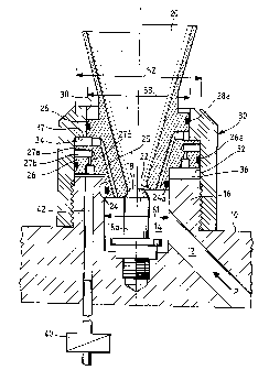
drawing in which the sole figure is a section view of an
embodiment of a gas gating device of the invention, the
gate being shown in its closed position in the left half-
section of the figure and in its open position in the
other half-section.
In this figure, reference 10 designates a base
secured to the body of a spacecraft to be controlled and
on which a gating device is mounted for gating hot gas
coming from a gas generator (not shown) via a feed duct
12 passing through the base 10. The duct 12 opens out to
the inside of a chamber 14 from which the gas can be
selectively ejected through a nozzle 20. The chamber 14
is defined in part by a tubular portion 16 projecting
from the base 10.
A plurality of similar devices subjected to
individual on/off control are mounted around the body of
the spacecraft so as to control the attitude thereof.
Communication between the chamber 14 and the nozzle
20 is opened and closed by controlling the spacing
between a plunger 18 and a seat 22 or by bringing them
into mutual contact.
The plunger 18 is situated at the end of a rod 18a
extending axially in the chamber 14 and screwed to the
bottom thereof, so that the plunger is fixed relative to
the base 10.
The seat 22 is formed at the end of a tubular
portion extending the nozzle 20 upstream relative to the
direction in which gas flows through the diverging
portion of the nozzle. Going downstream from the
upstream end, the tubular portion has a first annular
portion 24, a second annular portion 26 of outside
diameter greater than that of the portion 24, and a third

21 88393
annular portion 28 of diameter smaller than that of the
portion 26. The seat 22 is formed around the central
passage of the annular portion 24 and at the end thereof,
the portion 24 being capable of sliding in sealed manner
in the chamber 14, there being an annular sealing gasket
24a interposed between them.
Ejection or non-ejection of hot gas through the
nozzle 20 is controlled by moving the nozzle so as to
move the seat 22 away from the plunger 18 or so as to
press thereagainst. The nozzle is controlled directly by
the hot gases conveyed by the nozzle in the manner of a
free piston electropneumatic valve.
Thus, an annular sleeve 30 is screwed on the tubular
portion 16 of the base 10 so as to define a cylinder 32
in which the annular portion 26 of the nozzle 20 can
slide and form a piston which subdivides the inside
volume of the cylinder 32 into a first chamber 34 and a
second chamber 36. In its end portion 38 remote from the
base 10, the sleeve 30 has an inside section that is
smaller than the section of the cylinder 32 such that the
annular portion 28 can slide therein without clearance,
there being an annular sealing gasket 28a interposed
between them. The inside walls of the cylinder 32 and of
the end portion 38 of the sleeve are connected to each
other via a shoulder 37.
In this way, the three portions 24, 26, and 28 of
the nozzle slide in cylindrical portions 14, 32, 38 of
corresponding respective diameters, with the internal
sections S1, S2, and S3 of the chamber 14, the cylinder
32, and the portion 38 being such that S2 > S1 and
S2 > S3.
Passages 25 formed in the nozzle body 20 put the
chamber 14 permanently into communication with the
chamber 34 such that said chamber is constantly
pressurized to the pressure P of the hot gas. It will be
observed that the gasket 28a isolates the chamber 34 from
the outside.

2 1 88393
~_ 5
The piston 26 is provided with an annular sealing
gasket 26a pressed against the wall of the cylinder 32.
Nevertheless, communication having a leakage or small
flow section is established between the chamber 34 and
the chamber 36. In the example shown, this communication
passes via a leakage section 27a between the cylinder 32
and the downstream portion of the piston 26 adjacent to
the cylinder 34, via three blind radial holes 27b formed
in said downstream portion of the piston extending from
its peripheral surface, and via longitudinal holes 27c
putting the holes 27b into communication with the chamber
36.
The chamber 36 is isolated from the chamber 14 by
the gasket 24a, but it communicates with a pilot valve 40
via an exhaust duct 42 passing through the base 10. The
valve 40 may be an electromagnetically controlled valve,
for example.
The position shown in the right half-section of the
figure corresponds to the pilot valve 40 being closed.
The chamber 36 is pressurized to the pressure P of the
hot gas because of the communication established with the
chamber 34. Since the surface area of the piston 26
exposed to the pressure P in the chamber 36 is greater
than that exposed to the same pressure in the chamber 34,
the piston 26 is in its downstream position in abutment
against the shoulder 37. The valve seat 22 is at a
distance from the plunger 18 such that the hot gas coming
from the feed duct 12 is ejected through the nozzle 20.
When the pilot valve 40 is opened, the sudden drop
in pressure in the chamber 36 causes the piston 26 to
return and the seat 22 to come into contact with the
plunger 18, thereby closing off communication between the
duct 12 and the nozzle 20 (left side of the figure).
The gate is opened and closed directly by drive from
the hot gas, thereby enabling rapid and effective
switching to be performed without calling on an auxiliary
fluid. The control member is acting on a pilot valve and

2 1 88393
not directly on the main gate, which requires less power
and makes it easier to solve the problem of thermally
isolating it from the hot gas while using a structure
that is more compact.

Representative Drawing
A single figure which represents the drawing illustrating the invention.
Administrative Status

2024-08-01:As part of the Next Generation Patents (NGP) transition, the Canadian Patents Database (CPD) now contains a more detailed Event History, which replicates the Event Log of our new back-office solution.

Please note that "Inactive:" events refers to events no longer in use in our new back-office solution.

For a clearer understanding of the status of the application/patent presented on this page, the site Disclaimer , as well as the definitions for Patent , Event History , Maintenance Fee  and Payment History  should be consulted.

Event History

Description Date
Time Limit for Reversal Expired 2008-10-21
Letter Sent 2007-10-22
Inactive: IPC from MCD 2006-03-12
Inactive: Late MF processed 2004-02-24
Letter Sent 2003-10-21
Grant by Issuance 2002-02-19
Inactive: Cover page published 2002-02-18
Pre-grant 2001-11-23
Inactive: Final fee received 2001-11-23
Notice of Allowance is Issued 2001-06-01
Letter Sent 2001-06-01
Inactive: Approved for allowance (AFA) 2001-05-14
Letter Sent 2000-10-10
Inactive: Status info is complete as of Log entry date 2000-10-10
Inactive: Application prosecuted on TS as of Log entry date 2000-10-10
Amendment Received - Voluntary Amendment 2000-09-08
Request for Examination Requirements Determined Compliant 2000-09-08
All Requirements for Examination Determined Compliant 2000-09-08
Letter Sent 1999-07-08
Inactive: Multiple transfers 1999-03-23
Letter Sent 1997-11-18
Application Published (Open to Public Inspection) 1997-04-21

Abandonment History

There is no abandonment history.

Maintenance Fee

The last payment was received on 2001-09-21

Note : If the full payment has not been received on or before the date indicated, a further fee may be required which may be one of the following

  • the reinstatement fee;
  • the late payment fee; or
  • additional fee to reverse deemed expiry.

Patent fees are adjusted on the 1st of January every year. The amounts above are the current amounts if received by December 31 of the current year.
Please refer to the CIPO Patent Fees web page to see all current fee amounts.

Owners on Record

Note: Records showing the ownership history in alphabetical order.

Current Owners on Record
SOCIETE NATIONALE D'ETUDE ET DE CONSTRUCTION DE MOTEURS D'AVIATION "SNECMA"
SOCIETE EUROPEENNE DE PROPULSION
Past Owners on Record
ANDRE DUMORTIER
JEAN-GABRIEL FAGET
Past Owners that do not appear in the "Owners on Record" listing will appear in other documentation within the application.
Documents

To view selected files, please enter reCAPTCHA code :


To view images, click a link in the Document Description column (Temporarily unavailable). To download the documents, select one or more checkboxes in the first column and then click the "Download Selected in PDF format (Zip Archive)" or the "Download Selected as Single PDF" button.

List of published and non-published patent-specific documents on the CPD .

If you have any difficulty accessing content, you can call the Client Service Centre at 1-866-997-1936 or send them an e-mail at CIPO Client Service Centre.

({010=All Documents, 020=As Filed, 030=As Open to Public Inspection, 040=At Issuance, 050=Examination, 060=Incoming Correspondence, 070=Miscellaneous, 080=Outgoing Correspondence, 090=Payment})


Document
Description 
Date
(yyyy-mm-dd) 
Number of pages   Size of Image (KB) 
Abstract 1997-03-11 1 15
Description 1997-03-11 6 237
Claims 1997-03-11 1 33
Drawings 1997-03-11 1 37
Representative drawing 2002-01-14 1 18
Claims 2000-09-07 1 37
Representative drawing 1997-11-30 1 37
Courtesy - Certificate of registration (related document(s)) 1997-11-17 1 116
Reminder of maintenance fee due 1998-06-24 1 111
Acknowledgement of Request for Examination 2000-10-09 1 178
Commissioner's Notice - Application Found Allowable 2001-05-31 1 164
Maintenance Fee Notice 2003-12-15 1 174
Late Payment Acknowledgement 2004-03-16 1 166
Maintenance Fee Notice 2007-12-02 1 173
Correspondence 2001-11-22 1 29
Correspondence 1996-11-17 1 43
Fees 1999-10-05 1 37
Fees 2001-09-20 1 38
Fees 1998-09-22 1 42
Fees 2002-09-19 1 38
Fees 2000-09-28 1 43
Correspondence 2004-02-09 2 75
Fees 2004-02-23 2 69