Note: Descriptions are shown in the official language in which they were submitted.
W O 95133519 218 9 01 ~ PCT~SE95100695
POSITIONING DEVICE AND METHOD FOR RADIATION TREATMENT
Field of the Invention:
This invention relates to a method and device for
r
treating a patient with ionizing radiation. In the
practice of the invention, a patient is moved relative to
an ionizing radiation source during treatment. By moving
the patient during treatment, it is possible both to
minimize radiation delivered to areas outside a target
volume and to take into consideration, in treatment plan-
ning, the biological proterties of different areas inside
and outside the target volume.
Background of the Invention:
It is known that exposure of tissue to ionizing
radiation will kill the cells exposed. In the process of
conventional radiation therapy, however, significant
volumes of normal tissue in addition to pathological
tissue, are exposed to harmful levels of radiation.
Several methods have been employed in the prior art
to minimize the exposure of healthy tissue to ionizing
radiation. For example, devices which direct radiation at
the tumor from a number of directions have been used. In
such devices, the amount of ionizing radiation emanating
from each source of radiation is less than that which is
necessary to destroy tissued. Rather, tissue destruction
occurs where the radiation beams from multiple sources
converge, causing the radiation level to reach tissue-
destructive levels. The point of convergence of the center
of multiple radiation beams is referred to herein as the
"focus point". The radiation field surrounding a focus
point is herein referred to as the "focus volume." The
size of the focus volume can be varied by varying the size
of the intersecting beams.
One such radiation appliance sold under the name
GAMMA KNIFE (Elekta Instruments $.A.) Comprises an
ionizing radiation shield having a substantial number of
ionizing radiation sources. Radiation passes through a
number of channels all of which lead toward a common focus
WO 95133519 ~ 18 9 019 p~~E95100695
2
point in a recess within the radiation shield. Such a
system is referred to, and described in, US patent
4 780 898. Another system commonly termed a LINAC (or
linear acceleration) involves an ionizing radiation source
which moves circumeferentially around a focuspoint
delivering a series of beams of ionizing radiation through
the focus volume. A patient's head, immobilized in a
stereotactic instrument which defines the location of the
treatment target in the patient's head, is secured by a
system which positions the treatment target in coincidence
with the above-mentioned focus point.
The ionizing radiation in the focus volume of these
radiation appliances is intense compared to the radiation
emanating from each individual beam of the device. Areas
outside of the focus volume receive less substantial
amounts of ionizing radiation. Therefore, pathological
tissue can be treated while avoiding surrounding healthy
areas.
In general, the focus volume is spherical because the
intersection of multiple radiation beam cross sections
approximately form a sphere of constant radiation density
at each point equidistant from the focus point. As a
result, When the shape of the pathological tissue volume
is not substantially spherical, either some areas of
pathological tissue do not receive enough radiation or
other areas of healthy tissue receive too much radiation.
In other words, variations in radiation sensitivity within
the focus volume cannot be taken into acount. To ensure
that the whole volume of pathological tissue is fully
exposed to the radiation field, the radiation team is
obliged to deliver damaging doses of radiation to healthy
tissue within the focus volume.
It is possible to reduce the volume of healthy
tissue receiving high ionizing radiation doses by reducing
the size of the focus volume and manually repositioning
the patient a number of times such that the different
positions of the various focues volumes would effectively
WO 95/33519 PCTISE95/00695
3
cover the entire pathological tissue volume. While this
method allows increased conformity between pathological
tissue volumen and shape and the volume receiving high
i
radiation doses, the time required to manually reposition
a patient a sufficient number of times for the selected
focus volume size to effectively cover-the pathological
tissue can require unreasonably long treatment periods.
Moreover, each manual reposition introduces the potential
for mistakes with resultant increased radiation of helthy
tissue.
A second potential means for minimizing the
irradiation of healthy tissue would be to vary individual
beam size and intensities whereby the shape of the focus
volume could be modified to conform more accurately With
the pathological tissue volume. With the many possible
combinations of incident beam sizes and intensities to
be
interactively evaluated by the radiology team in order
to
find a radiation dose distribution appropriate for
treating a pathological tissue volume having a specific
shape, the experience of the radiotherapy team in choosing
the beam sizes and intensities becomes a significant
factor in the efficiency and effectiveness of the
radiation treatment.
A further solution involves the projection of a focus
volume of ionizing radiation onto a treatment area. Such
a
technique is described in, for example, Experimental
Verification of an Algorithm, for Inverse Radiation
Therapy Planning
Radiotherapy and Oncology
17 (1990 )
,
,
359-368. According to this article, it is impractical to
move the patient with respect to a fixed focus point. This
conclusion was based on Therapy Planning and Dosimetry
for
the Pion Application at the Swiss Institute for Nuclear
Research, Radiation and Environmental Biophysics, 16,
205-209 (1979), which was reported to have demonstrated
that dynamic movement of the patient in a pion generaton
was not feasible.
R'O 95!33519 PGTlSE95/00695
2189019
4
Thus, although the prior art suggests radiation
treatment of an object in which the dose distribution
closely conforms to the treatment area within the object,
the methods are dependent on the skill and experience of
the radiology team, involve potential errors during manual
repositioning and/or require prolonged treatment times. In
contrast to these prior art methods, the present invention
- by means of automatic positioning and repositioning of a
target area relative to a focus volume - eliminates the
risks of manual error, allows use of smaller-focus
volumes, thereby improving conformity between a radiation
field and a target volume and reducing the need for trial
and error approach associated with multiple size focus
volumes, and shortens the treatment planning time. In
addition, contrary to the teaching of the prior art, the
present invention permits dynamic movement of an object
relative to a radiaton source, whereby greater local
conformity of dose delivery to pathological tissue volume
and shape becomes possible by movement at rates which
modulate radiation deposition based on the tissue cellular
properties such as radiation sensitivity both inside and
outside of the target volume.
Summary of the Invention:
The present invention provides a medical radiation
treatment method and apparatus having a focus volume, the
position of which remains fixed with respect to the
ionizing radiation source but is variable with respect to
the object to be radiated. In the practice of the
invention, an object is moved with respect to the focus
volume of an ionizing radiation source whereby a plurality
of subareas within the object are subjected to varying
radiation intensity levels for varying dwell-times. The
dynamic movement is guided by a computer controlled
positioning device to provide a radiation dose
distribution. The radiation dose distribution closely
conforms to a desired radiation dose distribution taking
into account both the biological response of the various
WO 95!33519 p ~ 9 PCT/SE95/00695
tissues being subjected to radiation and the shape of the
target volume. The focus volume size and shape may he
varied in cooperation with the movement of the object to
further optimize the radiation treatment.
5 A determination of the focus volume size, intensity,
a
and dwell time of the focus volume in the target area,
is
made by initially dividing up the specified treatment
volume into volume elements or voxels. Biological
characteristics of the treatment volume are then assigned
to each voxel. A probability for achieving complication
free control of pathological tissue is then calculated
for
each voxel based on the biological characteristics. The
energy deposition incident to each voxel which is needed
to provide this probability of complication free tumor
control is thereupon calculated. Finally, from the energy
deposition incident on each voxel, the dwell time of the
focus volume at particular voxels is determined. Once the
dwell time has been determined, it is possible to
determine the order of movements necessary to position
the
object with respect to the focus volume to deliver the
necessary radiation for each voxel.
A device which allows a patient to be dynamically
positioned with respect to the focus point is used to
practice the method of this invention. In this device,
a
computer is used to generate a number and order of motor
control movements which cause the target volume to be
moved and positioned with respect to the focus point for
the requisite time. In a preferred embodiment, a
positioning device is attached to a suspension arrangement
which is secured to a radiation appliance and is
translatable in the X, Y and Z directions via two
electronicallly controlled motor assemblies.
Brief Description of the DrawincTS:
Fig. 1 illustrates a radiation treatment system
according to the present invention.
WO 95/33519 ~ ~ ~ PCTlSE95100695
6
Fig. 2 illustrates a flow chart for a computer
program for use in a radiation treatment system according
to the present invention.
Fig. 3 illustrates a modulator suitable for use in a
radiation treatment appliance according to the present
invention.
Fig. 4 illustrates an alternate form of modulator
suitable for use in a radiation treatment appliance
according to the present invention.
Fig. 5 illustrates a suspension system for moving a
positioning device with respect to a radiation source
according to the present invention.
Fig. 6 depicts the embodiment of Fig. 5 along
section VI-VI.
Detailed Description of the Invention:
Fig. 1 illustrates a radiation treatment system
useful for carrying out the radiation treatment method
according to the present invention. In particular, Fig. 1
illustrates the coordination of various parts of a
radiation treatment appliance 103, having an
electronically controlled positioning device 105 and an
ionizing radiation unit 110, to deliver controlled
radiation to selected parts of an object under treatment.
The use of an electronically controlled positioning device
in combination with calculated radiation doses for
individual voxels based on biological radiation response
characteristics enables the radiation system illustrated
in Fig. 1 to dynamically control the radiation treatment
of the target by moving the target with respect to the
focus point. Specifically, the radiation treatment system
of Fig. 1 optimizes the radiation delivery of individual
voxels on a real time basis so that radiation absorbed in
the target conforms to the desired radiation doses
associated with desired biological responses of the
various tissues to be treated.
R'O 95f33519 PCTISE95I00695
1 218919
Input data system 150, illustrated in Fig. 1,
comprises a system for generating and/or storing three
dimensional geometric coordinates of the treatment volume
within an object such ms a patient. This system also
generates and/or stores the types of biological responses
of the target volume and surrounding tissues to be
treated. The input data system 150 transmits the treatment
volume data to the host computer system 100. The input
data system 150 is, for example, a conventional computer
graphics system which stores three dimensional coordinates
of a treatment volume and associated subvolumes of the
treatment volume with data representing biological
properties of the subvolumes. The host computer 100
converts this data into a series of motor control,
radiation beam size, and radiation beam energy output
control signals through a computer program such as
illustrated in Fig. 2. The host computer sends radiation
control signals to the radiation modulators 45 of the
radiation unit 110 device over wire 130 to control the
size and/or intensity of the radiation beams emanating
from the radiation source to irradiate the treatment
volume.
The radiation unit 110 includes an radiation source
which projects one, two or more beams of radiation and
a
means to control radiation beam size, such as modulators
45. The radiation source of the radiation treatment
appliance may be any of variety of conventional ionizing
radiation sources which produce an effective focus volume
of radiation. A focus volume is typically formed by the
intersection of plurality (two to several hundred) of
radiation beams emanating from the radiation source. The
beam axes are directed at a fixed point with respect to
the radiation source. The focus volume is the summation
(over the volume of the intersecting radiation beams) of
radiation densities from each of the intersecting
radiation beams. An effective focus volume can also be
formed by directing the axis of a single radiation beam
GVO 95133519 ' ~ PCT/SE95100695
8
through a fixed point from a plurality (typically 2 to
360) of different angles. Such a technique is commonly
used in linear accelerator type radiation units.
The host computer 100 also sends the motor control '
signals through wires 120 to each of a first, a second and
a third motor assemblies, each having motors 21, 22 and '
25, within the electronically controlled positioning
device 105. The first and second motor assemblies
cooperate so that motors 21, 22 and 25 in the first
assembly always move precisely the same distance as motors
21, 22 and 25 in the second assembly. The first and second
motor assemblies are each connected to feedback system 170
which compares the translation distance of motors 21, 22
and 25 in the first motor assembly with the translation
distances of motors 21, 22 and 25 respectively of the
second motor assembly. When a pair of cooperating motors
21, 22 or 25 do not have approximately (i.e.>-0.2 mm
difference) the same translation distance, an error
detection feedback system 170 generates a feedback error
signal to terminate all motor movement and radiation
exposure which is sent through wire 180 to the host
computer system 100. When the computer system has
terminated motor movement and radiation exposure due to
this feedback signal, the motors can then ba recalibrated,
and treatment restarted. Feedback system 170 also monitors
the radiation intensity by monitoring the beam sizes
produced by the radiation modulators which form the focus
volume. The beam size is controlled by the host computer
100 through radiation modulators 45 for each beam. When a
modulator forms a beam having a crass section larger or
smaller than desired, then the error detection feedback
system 170 transmits an error signal to the host computer
which, in turn, generates control signals to the
cooperating motors which move the patient away from the
focus volume of the radiation treatment appliance.
Alternatively, when the error detection feedback system
170 senses that the radiation beam size is not correct,
WO 95/33519 PCT/SE95/00695
2189d19
9
then feedback system 170 transmits an error signal to the
host computer 100 which then turns off the radiation
source.
Manual controller 160 consists of a joystick
mechanism or the like which generates signals for manually
4
controlling cooperating motors 21, 22 and 25. These
signals are transmitted to both sets of cooperating motors
21, 22 and 25 over wire 120 through host computer system
100. Monitor 165 dispays an image corresponding to a focus
point and a.treatment volume as the treatment volume is
moved with respect to the focus point in response to the
signals sent to cooperating motors 21, 22 and 25.
Fig. 2 illustrates a computer program 200 used by a
computer 100 of the radiation treatment system according
I5 to the present invention for controlling radiation
deposition within the treatment volume of an object by
automatically moving the object with respect to the focus
volume. The computer program generates signals to control
motors which move the object so as to have a radiation
focus volume dwell in a location for a sufficient time to
deliver the appropriate radiation intensity for that
location. Initially, the three dimensional coordinates of
the treatment volume and the biological characteristics
of
the tissue in the treatment (and surrounding) volume are
generated and sent 203 to the computer system. The
treatment volume is then segmented 205 into volume
elements or voxela having a minimum volume smaller than
the focus volume which is generated at the intersection
of
the radiation beams. Biological responses to radiation of
tissue associated with the treatment area are then
assigned 220 to the voxels. The specification of tissue
types allows the treating physician to treat, through
computer controlled radiation, different types of tumorous
regions which may react differently to specific radiation
doses.
WO 95/33519 -~ ~ ~ '~ '~ ~ ~ PCT/SE95100695
Once the tissue types for each voxel have been
established, the computer program 200 selects a desired
biological response 230 for each voxel which depends on a .
radiation dose for that voxel. This selection generates a
5 desired radiation dose distribution ~(r) for the treatment
4
volume. A specific example of such a biological response
is the maximum probability of complication free control of
pathological tissue (P+) chosen for each voxel. P+ is the
probability of achieving control for a specific type of
10 tissue for a specified radiation dose minus the
probability of fatal complications for that-radiation dose
and tissue type. The data relating to the probability of
control is provided to the computer program from ongoing
or previously published clinical studies. Selecting a
maximum P+ for each voxel generates an optimum radiation
distribution for pathological tissue control because each
selected P+ has an associated radiation dose. The
generation of P+ can alternately be defined as the
probability of control for-a specific type of tissue for a
specified radiation dose minus the probability of adverse
(not necessarily fatal) complications from that radiation
dose for that type of tissue. Alternatively, biological
responses of tissue to radiation may be selected depending
on the location of the treatment volume relative to other
treatment volumes. Further, other biological responses of
tissue to radiation may be chosen which would generate
different radiation dose distributions for the tissue.
These selections of biological response provide a treating
physician more degrees of freedom in treatment doses for
different types and locations of tissues.
Once a desired radiation dose ~(r) for each voxel has
been generated in step 230, the computer program 200 must
specify how any particular voxel will receive the required
dose. This is a problem because radiation beams focused on
any one voxel w111 contribute radiation exposure to
adjacent voxels. The computer program 200 solves this
probelm by first determining 240 an energy deposition
W O 95!33519 PCTISE95100695
~~ ,~~~~~ 9
11
kernel H(r,r') which is the mean specific energy imparted
to a point r per unit energy incident on a volume centered
at r': The program 200 assumes that H(r,r') is spatially
independent. That is, the energy imparted at point r from
a focus volume centered at r' is only a function of the
distance between r and r'. A consequence of this
assumption is that the calculated dose distribution D(r)
can be expressed as the integral of the density F(r') of
energy deposition kernels H(r,r') over the same volume.
The integral expression is then solved via conventional
analytical or iterative techniques for one of D(r) or
F(r') given H(r,r') and either F(r') or D(r) respectively.
The energy depostion kernels H(r,r') are known and are
inputs for the integral expression because the energy
distribution associated with the physical intersection
of
multiple radiation beams of a given cross section for any
one focus volume is known. The kernel may be simulated,
for example, by rotating a normalized beam cross section
through 360 degrees. Energy deposition kernels H are
assigned to each voxel in step 240.
Once the energy deposition kernels for all voxels
have been determined, the calculatd radiation dose
distribution D(r) is determined by iteratively solving
for
the radiation density F(r'). That is, an initial density
FO(r'), for each voxel is assumed, multiplied by the
deposition kernel for each voxel, and then summed over
the
total treatment volume. The initial calculated dose
distribution DO(r) is then compared 250 to the desired
radiation dose ~(r) and an error term is generated. The
assumed initial density is adjusted F1(r') as a function
of the error term and the next D1(r) is calculated. This
iteration procedure continues until the calculated D
(r)
n
after n iterations is sufficiently close to the desired
~(r). The initial assumed density is chosen to deliver
a
substantial overdose to the treatment area. The error term
represents a decrease in beam density. As a result, the
convergence of the iterative calculations will guarantee
R'O 95!33519 ~ PCTISE95100695
12
that the treatment area will not receive less than the
desired dose. This consideration assures that there will
not be an underexposure of a treatment area. The result of
iteration step 250 is a density F(r) for each voxel which
specifies the time duration that a specific kernel should
dwell on any one voxel. Typically, the iteration converges
at approximately n=200 or before.
Once the duration of a specific kernel on any
particular voxel is known, the computer 100 generates
(270) control signals which are sent to the modulators 45
and to both sets of cooperationg motors 21, 22 and 25. The
control signals sent to the modulators 45 adjust the
radiation beam size, and hence the kernel size for any
selected voxel. The control signals sent to the
cooperation motors, 21, 22 and 25 move the patient with
respect to the focus volume such that the radiation energy
incident on the focus volume has a duration on any
particular voxel only long enough to deliver the required
beam density to that particular voxel. The movement of the
target volume relative to the focus volume may be
continuous while the target volume is exposed to radiation
and the speed may be slowed or accelerated to result in an
appropriate dwell time. Alternatively, movement may
comprise sequential movement or re-positioning of the
target volume in a multiplicity of positions relative to
the focus volume. In this case, the radiation source is
pulsed off while the target volume is moved and pulsed on
while the target volume is stationary. As used herein, the
term "sequential movement" means that stopping the
movement of the target volume, irradiation the target,
volume, and moving the target volume again. In a preferred
embodiment, the focus point is not moved outside of the
object containing the target volume while this sequential
re-positioning is occurring.
Cooperating motors 21, 22 and 25 as well as
modulators 45 will continue to control the radiation
deposited in the patient until the feedback system 170 of
WO 95133519 PCT/SE95/00695
13
the radiation treatment system detects that either the
opposing motors are not moving synchronously or that one
- or more of the radiation sources are not producing the
required beam intensity or that the modulators 45 are not
producing the required beam shape. When either of these
conditions occur, the computer program will generate 280
commands to stop motor movement and/or atop radiation
exposure. At this point, the program 200 will prompt the
user 285 for an evaluation of whether to proceed with the
remaining computer controlled treatment or proceed with
manual operation. When the user wants to return to
computer control, a new sequence of control movements are
generated 270 taking into account that part of the
previous treatment already accomplished. When the user
requests manual operation, the program releases control
over the radiation treatment system and transmits signals
from the manual controller 160 to both sets of cooperating
motors 21, 22 and 25.
The apparatus described above may be adapted to any
radiation unit 110 which delivers ionizing radiation to
a
focus volume, such as a Gamma KnifeTM or LINAC radiation
treatment system, or a heavy particle beam system. In
order to control radiation delivery, t~-:e channel(s)
through which radiation is delivered may be provided with
radiation modulators 45 such as shown, in Fig. 3. The
radiation modulators 45 may be configured as oppoaingly
faced lead plates or wedges of the like which are moveable
relative to each other to form a variable slit of opening
for modulating the shape or ii~tensity of the radiation
beam passing though the opening.
Fig. 3 illustrates a top view of modulator 45. In
- particular, moveable lead plate 60 is disposed over
moveable lead plate 70. Plate 60 has a diamond shaped
opening 62 therethrough and plate 70 has a diamond shaped
opening 72 therethrough. Openings 62 and 72 converge to
form opening 65 through both plates 60 and 70. The
relative position of plates 60 and 70 determine the size
WO 95133519 ~ PCT1SE95100695
14
of opening 65 through which a radiation beam passes. The
size of opening 65 shapes the radiation beam passing
through opening 65. ,
Fig. 4 illustrates an alternate form of modulator
suitable for incorporation in the present invention. The
modulator illustrated in Fig. 4 1s formed from two sets 80
and 82 of opposingly oriented slats of radiation blocking
material. The slats may also be formed of radiation
modulating material which transmits selective intensities
of radiation depending on the energy of the incident
radiation. Individual slats within a first or second set
form a planar surface substantially perpendicular to the
direction of the radiation beam. The two sets of slats are
oriented with respect to each other such that they form
the radiation beam cross section. The slats are moveable
with respect to each other, and as they are moved, the
beam cross section is modulated. For example, slat 80(a)
moves relative to slat 82(a) to form part of opening 85
and slat 80(b) moves relative to slat 82(b) to form
another part of opening 85. Any other suitably shaped and
sized modulator may be used in the practice of the
invention.
The radiation sources within the radiation unit 110
are preferably ionizing radiation sources which emit high
energy (gamma or x-ray) photons or heavy charged
particles.
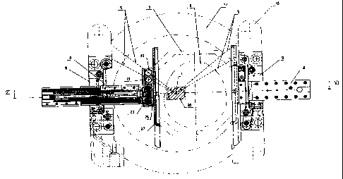
As illustrated in Fig. 5 and 6 an object such as a
patient's skull 6 is immobilized with respect to a
fixation device 5 within an electronically controlled
positioning device 105. The electronically controlled
positioning device 105 includes a base 17, a suspension
system, and a fixation device 5. The fixation device 5 is
moveable with respect to the radiation device. During
treatment, the fram 5 is moved by the positioning device
to the positions necessary to allow the focus point F of
the radiation beams to be located within the target volume
28. The focus point is at the intersection of the
WO 95/33519 PCTISE95100695
plurality of radiation beams S. The positioning device
is
secured to the radiation appliance by a base 17. The
. suspension system, attached to the base 17 by bracket 18,
translates the fixation device 5 in the horizontal and
5 vertical planes, i.e. the 3 dimensional coordinate system
,
with respect to the radiation source and the focus point
F. This suspension arrangment comprises a pair of
horizontal beams 8 or the like which are oriented in line
with each other, translatable in their lengthwise
10 direction, and slidably supported in associated guides
9
of bracket 18.
The outer end of each beam 8 is connected to the
associated part of the bracket through a screw jack means
19 which via gear assembly 20 is linked to an
15 electronically controlled motor 21 within the beam 8. The
motor 21 is in a parallel orientation to the screw
components of the screw jack means 19, as shown in Fig.
6.
The motor 21 is preferably operated via NC control from
the computer or the like (not illustrated) following a
dedicated computer program. Both motors 21 function
cooperatively and form a motor assembly arranged to
translate the stereotactic instrument 5 in the X
direction.
Additionally, adjacent the inner end of each beam 8,
an electronically controlled motor 22 is connected to,
and
supported by, a beam 23 which encloses a screw jack means
24 also connected to the motor 22. The beams 23 are
parallel and disposed opposite each other. The motors 22
are also electronically controlled, operated via NC
control from the computer and cooperate to form a motor
assembly arranged to translate the stereotactic instrument
in the Z direction.
A further electronic motor 25 is connected to, and
supported by, a beam 26 adjacent the inner end of each
beam 8, beyond the respective beam 23. The beams 26 are
mutually parallel and disposed opposite each other. Each
beam 26 is attached to the static portion of a respective
W 0 95133519 PCTISE95100695
2189D~9
16
screw jack means 24 and guided with guides (not shown).
The screw jack means (not shown) are further connected to
the respective motor 25. The motors 25 are also .
electronically controlled, operated via NC control from
said computer or the like and cooperative to form a motor
assembly which is arranged to translate the stereotacic
instrument 5 in the Y direction. The screw jack means (not
shown) supports an attachment means 27 to releasably
secure the stereotactic instrument in a defined position
in the suspension arrangement.
A fixation device 5 suitable for use in this
invention when immobilizing a patient's skull in the
positioning device is, for example, a stereotactlc frame.
The frame is fixed to the skull of the patient and mounted
to the suspension system. The frame may be fixed to the
skull of the patient by means of surgical twist drills
passing through skin and looking into underlying bone.
Alterntively, the fixation device 5 may be ane which is
non-invasive and/or allows the frame to be relocatably
positioned on the patient.
The pair of cooperating motors 21 are opposingly
disposed and operate in synchronization. In particular,
when the motors do not move the stereotactic frame
concurrently the same distance, then the error detection
feedback system 170 (not shown) connected to the pair of
cooperating motors 21 signals the computer that the
orientation of the stereotactic fram is not correct and
the program moving the sterotactic frame is stopped so
that the stereotactic frame can be reoriented.
A personalized computer program for a patient's
treatment controls the movements of each motor assembly
21,21; 22,22 and 25,25. In this way, the stereotactic
instrument 5 and therefore the patient's skull 6 is moved
in the X, Y and Z directions within the helmet 17 and
different parts of the treatment target 28 are
successively positioned at the focus point F for various
time periods in accordance with said program. The
WO 95f33519 PCTISE95100695
17
movements of both of the motors in each motor assembly are
continuously checked against each other by the computer
and if the movement of one motor differs from the
respective cooperation motor, the computerissues a stop
signal and treatment is suspended. Computer operation
gives enhanced reliability and even the posaibillty, if so
desired, to break off treatment and to afterwards resume
treatment at the appropriate point in the computer
program.
While this invention has been particularly described
and illustrated with reference to particular embodiments
thereof, it will be understood by those of skill in the
art that changes in the above description or illustrations
may be made with respect to form or detail Without
departing from the spirit-or scope of the invention. In
particular, any controlled movement means which allows the
object being irradiated to be moved relative to a
radiation source may be employed.
25
35
;_..,.: , ..~: y
v ,; )i'~r