Note: Descriptions are shown in the official language in which they were submitted.
21 89287
RCA 86,442
COLOR PICTURE TUBE HAVING A TENSIONED MASK
AND COMPLIANT SUPPORT FRAME ASSEMBLY
This invention relates to color picture tubes having
5 tensioned masks attached to support frames, and particularly to a
tube with a mask-frame assembly having a tensioned mask that is
attached to a compliant support frame.
A color picture tube includes an electron gun for forming
and directing three electron beams to a screen of the tube. The
10 screen is located on the inner surface of a faceplate of the tube
and is made up of an array of elements of three different color
emitting phosphors. An apertured mask, which may be either a
shadow mask or a focus mask, is interposed between the gun and
the screen to permit each electron beam to strike only the
15 phosphor elements associated with that beam. A shadow mask is
a thin sheet of metal, such as steel, that is contoured to somewhat
parallel the inner surface of the tube faceplate. A focus mask
comprises a dual set of conductive lines that are perpendicular to
each other and usually separated by an insulative layer. Both
2 0 shadow masks and focus masks can be constructed in the form of
tensioned masks. A tensioned mask is a stretched mask that is
maintained under tension by a support frame.
The frame used with a tension mask must have high
compliance, both to keep the tensioned strands of the mask tight
2 5 and to prevent over-stressing of the strands when the mask and
its support frame encounter a range of temperatures during
processing and tube operation. One existing design relieves mask
tension during tube processing by bending of the side members of
the frame. However, this design may result in a large variation in
30 compliance between the center and sides of the mask. Such
variation occurs because of uneven bending and twisting in the
frame members, which ultimately causes a reduction in wire
tension in some parts of the mask relative to the tension in other
parts. Although tubes with such mask frames have found wide
35 consumer acceptance, there is yet a need for further improvement
in tubes, to reduce the weight and cost of the mask-frame
21 89287
2 RCA 86,442
assemblies used therein, while providing a compliant structure
that is very resistant to bending and twisting.
The present invention provides an improvement in a
color picture tube having a tensioned mask and a support frame,
5 each of which is rectangular and has two long sides paralleling a
central major axis and two short sides paralleling a central minor
axis. The mask is cylindrically contoured, with the mask being
curved along the major axis and straight along the minor axis.
The improvement comprises the support frame including two first
10 members paralleling the major axis and two second members,
attached to the ends of the first members, paralleling the minor
axis. Each of the first members comprises a first part having two
flanges, a first flange extending toward the screen and a second
flange perpendicular to the first flange, in an L-shaped cross-
15 section. The first flange varies in height along the first part, from
a minimum height at the ends thereof to a maximum height at the
center thereof. Each of the first members comprises also a second
part, which extends between the two flanges of the first part and
forms a triangle therewith in cross-section.
2 0 In the drawings:
FIGURE 1 is a top view, partly in axial section, of a color
picture tube embodying the invention.
FIGURE 2 is a side view, partly in axial section, of the color
picture tube of FIGURE 1.
FIGURE 3 is a perspective view of a tensioned shadow mask-
frame assembly.
FIGURE 4 is a perspective view of a tensioned focus mask-
frame assembly.
FIGURE 5 is a perspective view of the frame of FIGURE 3
30 with the mask removed.
FIGURE 6 is a partial cross-section view of the mask-frame
assembly taken at line 6-6 of FIGURE 3.
FIGURE 7 is a partial cross-sectional view of the frame taken
at line 7-7 of FIGURE 5.
FIGURE 8 is a partial cross-sectional view of a mask-frame
assembly during fabrication.
21 89287
3 RCA 86,442
FIGURE 9 is a partial perspective view of a frame with a
corner support assembly.
FIGURE 10 is a partial perspective view of another frame
embodiment, showing the use of pantographs between two
5 portions of the frame.
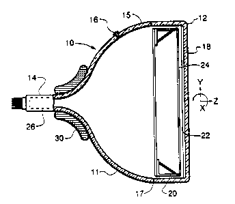
FIGURES 1 and 2 show a color picture tube 10 having a glass
envelope 11 comprising a rectangular faceplate panel 12 and a
tubular neck 14 connected by a rectangular funnel 15. The funnel
15 has an internal conductive coating (not shown) that extends
1 0 from an anode button 16 to the neck 14. The panel 12 comprises
a cylindrical viewing faceplate 18 and a peripheral flange or
sidewall 20 which is sealed to the funnel 15 by a glass frit 17. A
three-color phosphor screen 22 is carried by the inner surface of
the faceplate 18. The screen 22 is a line screen with the phosphor
1 5 lines arranged in triads, each triad including a phosphor line of
each of the three colors. A cylindrical tensioned mask 24 is
removably mounted in predetermined spaced relation to the
screen 22. The tensioned mask 24 may be either a shadow mask
or a focus mask. An electron gun 26, shown schematically by
20 dashed lines in FIGURES 1 and 2, is centrally mounted within the
neck 14 to generate and direct three inline electron beams, a
center beam and two side or outer beams, along convergent paths
through the mask 24 to the screen 22.
The tube 10 is designed to be used with an external
2 5 magnetic deflection yoke, such as the yoke 30 shown in the
neighborhood of the funnel-to-neck junction. When activated, the
yoke 30 subjects the three beams to magnetic fields which cause
the beams to scan horizontally and vertically in a rectangular
raster over the screen 22.
When the tensioned mask is a shadow mask 24', as shown in
FIGURE 3, it includes an apertured portion that contains a
multiplicity of elongated slits that parallel a central minor axis, Y,
of the mask. Each slit extends from near one long side of the
mask to near the other long side. The tensioned shadow mask 24'
3 5 includes two long sides 32 and 34 and two short sides 36 and 38.
The two long sides 32 and 34 parallel a central major axis, X, of
21 89287
4 RCA 86,442
the mask, and the two short sides 36 and 38 parallel the central
minor axis, Y, of the mask. When the tensioned mask is a focus
mask 24", as shown in FIGURE 4, it includes a plurality of
vertically extending strands 25, which are under tension, and a
5 plurality of horizontally extending wires 27 that are separated
from the strands 25 by insulators (not shown),
A frame 40, for use with either the tension or focus mask, is
shown in FIGURES 5, 6 and 7. The frame 40 is rectangular and
includes four major members, two first members 42 and 44 that
10 substantially parallel the major axis X, and two second members
46 and 48 that substantially parallel the minor axis Y. Each of the
first members 42 and 44 includes a first part 50 having two
flanges, a first flange 52 that extends toward the screen, and a
second flange 54 that is perpendicular to the first flange 52. The
15 two flanges are configured in an L-shaped cross-section. The first
flange 52 varies in height along the first part 50, from a minimum
height at the ends of the first part to a maximum height at the
center of the first part. Each first member 42 and 44 also
includes a second part 56 that is angled between the two flanges
20 52 and 54 of the first part 50, to form a triangle therewith in
cross-section. The second part 56 intersects the first flange 52 a
predetermined distance from the distal end of the flange 52, to
permit some flexibility of the cantilevered portion of the flange
52.
2 5 A method of attaching the mask 24' to the distal end of the
first flange 52 is shown in FIGURE 8. First, the long sides 32 and
34 of the mask are held by two vacuum supports 58 (one shown),
that are moved apart, as shown by force vector 60, to put the
mask under tension. At the same time, the distal ends of the first
30 flanges 52 are bent toward each other, as shown by force vector
62, with the distal ends in contact with the mask. Next, a welding
head 64 is moved along the mask, welding the mask to the distal
ends of the first flanges 52. Finally, the vacuum supports 58 are
removed and the excess portion of the mask is separated
35 therefrom. The spring-back of the distal ends of the flanges 52,
21 ~9287
S RCA 86,442
after removal of the force vector 62, maintains the mask under
tension.
FIGURE 9 shows a corner support assembly 66 that can be
used with the frame 40. In this embodiment, the two second
S members 46 and 48 are formed from solid metal bars, and the
ends thereof are angled with respect to the major and minor axes,
X and Y. These ends may either be perpendicular or nearly
perpendicular to the frame diagonals, which extend between
opposite corners of the frame. The support assembly includes a
10 plate 67 and spring 68. The bottom of the plate 67 is welded to
the angled ends of the second member 46, and the spring 68 is
welded to the distal end of the plate 67. An aperture in the
spring 68 engages a stud, which is located in a corner of the
faceplate panel of the tube.
Another frame 70 is shown in FIGURE 10. The design of the
frame 70 differs somewhat from that of the frame 40. Like the
frame 40, the first members 42' along the long sides of the frame
70 include a first part 50' having two flanges configured in an
L-shaped cross-section, a first flange 52' that extends toward the
2 0 screen and a second flange 54' that is perpendicular to the first
flange 52'. The first members 42' also include a second part 56'
that is angled between the two flanges 52' and 54' of the first part
50', to form a triangle therewith in cross-section. The second part
56' intersects the first flange 52' a distance from the distal end of
2 5 the flange 52', to permit some flexibility of the cantilevered
portion of the flange 52'. However, unlike the frame 40, the
frame 70 includes rectangularly shaped hollow pipes 72, instead
of solid bars, as second members 46' along its short sides. These
pipes could also be substituted into the first frame 40, in place of
3 0 the solid bars. A big difference between the frame 70 from the
frame 40 is the interconnection between the first and second
members. In the frame 70, this interconnection is made by
means of pantographs 74, wherein each pantograph comprises a
plurality of parallel plates 76. The function of the pantographs 74
3 5 is to allow the top and bottom first members 42' to move nearer
or farther from each other without any rotation of the first
21 89287
6 RCA 86,442
members. This permits frame compliance to be substantially
constant along the lengths of the top and bottom first members.
The - pantograph height, width, thickness and plate numbers are
determined by the available space and force and compliance
5 needed. In general, the available space controls the height and
width, the force controls the plates number and compliance
controls the thickness.