Language selection

Search

Patent 2189324 Summary

Third-party information liability

Some of the information on this Web page has been provided by external sources. The Government of Canada is not responsible for the accuracy, reliability or currency of the information supplied by external sources. Users wishing to rely upon this information should consult directly with the source of the information. Content provided by external sources is not subject to official languages, privacy and accessibility requirements.

Claims and Abstract availability

Any discrepancies in the text and image of the Claims and Abstract are due to differing posting times. Text of the Claims and Abstract are posted:

  • At the time the application is open to public inspection;
  • At the time of issue of the patent (grant).
(12) Patent: (11) CA 2189324
(54) English Title: CONTAINER FOR PRESSURIZED FLUIDS
(54) French Title: RECIPIENT POUR FLUIDES SOUS PRESSION
Status: Term Expired - Post Grant Beyond Limit
Bibliographic Data
(51) International Patent Classification (IPC):
  • B65D 08/22 (2006.01)
  • B65D 08/08 (2006.01)
(72) Inventors :
  • WHEATON, CHRISTOPHER SIMON COURTENAY (United Kingdom)
(73) Owners :
  • KEG SERVICES LIMITED
  • CYPHERCO LIMITED
(71) Applicants :
  • KEG SERVICES LIMITED (United Kingdom)
  • CYPHERCO LIMITED (United Kingdom)
(74) Agent: MARKS & CLERK
(74) Associate agent:
(45) Issued: 2005-09-20
(86) PCT Filing Date: 1995-04-20
(87) Open to Public Inspection: 1995-11-16
Examination requested: 2002-04-15
Availability of licence: N/A
Dedicated to the Public: N/A
(25) Language of filing: English

Patent Cooperation Treaty (PCT): Yes
(86) PCT Filing Number: PCT/GB1995/000890
(87) International Publication Number: GB1995000890
(85) National Entry: 1996-10-31

(30) Application Priority Data:
Application No. Country/Territory Date
9409322.6 (United Kingdom) 1994-05-10

Abstracts

English Abstract


A keg for a pressurized fluid is formed of a main body
part to respective open ends of which are secured upper and
lower ends parts each of the three parts being an injection
moulding of thermoplastics material and connected together by
welding. Around an internal surface of the main body part is
an integral continuous planar flange which serves to resist
outwards pressure on the body when the keg is pressurized, in
use, the flange defining a large central opening in the
interior of the keg. Ribs are formed integrally with the
internal body surface and flange, and extend around the
flange between respective pairs of first openings through the
flange, smaller second openings being aligned with, and
disposed at the inner end of the respective ribs.


French Abstract

Un fût (10), destiné à contenir un fluide sous pression, est constitué d'un corps principal (11) aux extrémités ouvertes duquel sont fixées des pièces d'extrémités supérieure et inférieure (14, 12), toutes ces parties étant moulées par injection d'un matériau thermoplastique et raccordées par soudage. Autour de la surface interne du corps principal (11), on trouve une collerette intégrée (21), continue et plane, qui permet à ce corps de résister à la pression extérieure quand le fût est mis sous pression pendant son utilisation, cette collerette définissant une grande ouverture centrale (22) à l'intérieur du fût. Des nervures (25), intégrées dans la surface interne du corps et dans la collerette, partent de chaque côté de cette collerette entre des paires respectives de premières ouvertures (23) traversant ladite collerette, des deuxièmes ouvertures (24), plus petites, étant alignées sur l'extrémité interne de leurs nervures respectives où elles sont disposées.

Claims

Note: Claims are shown in the official language in which they were submitted.

7
The embodiments of the present invention in which an
exclusive property or privilege is claimed are defined as
follows:
1. A container for pressurised fluid, in the form of a
substantially closed, hollow body of thermoplastics
material, the body having on its internal surface at least
one inwardly extending member, wherein the body comprises a
one-piece main body part, and wherein said at least one
inwardly extending member is rigid or substantially rigid,
extends continuously around the internal surface of said
one-piece main body part, and is formed integrally
therewith, to resist outwards pressure on the body when the
container is pressurized, in use.
2. The container according to claim 1, wherein the at
least one inwardly extending member is a flange defining a
large central opening in the interior of said main body
part.
3. The container according to claim 2, wherein said at
least one inwardly extending member is normal to a central
rotational axis of the main body part.
4. The container according to claim 3, wherein said at
least one inwardly extending member lies in a plane normal
to a longitudinal axis of the container, about which plane
the main body part is symmetrical.
5. The container according to any one of claims 1 to 4,
wherein at least one rib is provided at the junction of
said at least one inwardly extending member and said
internal surface of the main body part.

8
6. The container according to claim 5, wherein said at
least one rib is integral with said main body part and said
at least one inwardly extending member.
7. The container according to any one of claim 1 to 4,
wherein said at least one inwardly extending member is
provided with a multiplicity of openings for fluid flow
therethrough.
8. The container according to claim 5 or claim 6, wherein
a multiplicity of ribs is provided and said at least one
inwardly extending member is provided with a multiplicity
of openings for fluid flow, the ribs being disposed between
adjacent pairs of said openings.
9. The container according to claim 8, wherein said at
least one inwardly extending member is provided with a
multiplicity of further openings for fluid flow, said
further openings being aligned with the ribs respectively
in the inwards direction of the main body part.
10. The container according to any one of claims 4 to 9,
wherein the exterior of the main body part has indent means
extending to opposite sides of the plane.
11. The container according to any one of claims 1 to 10,
wherein the main body part is an injection moulding of said
thermoplastics material.
12. The container according to claim 11, wherein
respective upper and lower end parts are secured to

9
opposite ends of the main body portion, the end parts each
being an injection moulding of thermoplastics material.
13. The container according to claim 12, wherein the end
parts are each secured to the main body portion by welding.
14. The container according to any one of claims 1 to 13,
which is of circular cross-section.
15. The container according to any one of claims 1 to 14,
wherein the thermoplastics material is glass-reinforced.

Description

Note: Descriptions are shown in the official language in which they were submitted.


,~ wo 950585 218 9 3 2 4 P~~GB95/OU890
1
CONTAINER FOR PRESSURIZED FLUIDS
This invention relates to a container for pressurised fluid, particularly
alcoholic beverages such as beer.
Presently beer kegs are formed of stainless steel or are of thermoplastics
material, being produced by blow-moulding. Although easier and less
expensive to produce than a stainless steel keg, a blow-moulded keg of
thermoplastics material may have only a low working pressure and may
be susceptible to a volume increase under pressurisation.
An object of the invention is to provide an improved container for
pressurised fluid.
According to a first aspect of the invention, a container for pressurised
fluid has a substantially closed, hollow body of thermoplastics material
and on an internal surface of the body at least one inwardly extending
member which resists outwards pressure on the body when said
container is pressurised, in use.
According to a second aspect of the invention, a container for
pressurised fluid has a substantially closed, hollow body formed of at
least two parts secured together, each part being an injection moulding
of thermoplastic material.
The invention will now be described, by way of example, with reference
to the accompanying drawings, in which:
Figure 1 is a plan view of a pressurised fluid container of the invention,

WO 95130585 ~CTlGB95100890
219324
2
Figure 2 is a vertical sectional view through the container,
Figure 3 shows one form of diaphragm of the container,
Figure 4 shows the same form of diaphragm as in Figure 3, but for a
square container, and
Figure 5 is an enlarged section on line A-A of Figure 4.
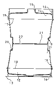
Figures 1 and 2 show a container for pressurised fluid which in the
particular application to which the invention is directed, is in the form of
a keg 10 for receiving pressurised alcoholic beverages, such as beer.
In the embodiment illustrated in Figures 1 and 2, the keg is generally
circular in cross-section, and is made up of a central, main part 11,
which is open at its opposite ends, a closed lower end part 12, which, as
shown in Figure 2, forms a bottom of the keg which rests on a surface
13, and an upper end part 14 which has a central circular opening 15
which can be closed by a bung or the like as required. It can be seen
that both end parts have an integral outer cylindrical enclosure 16
therearound, the end of each of which extends to terminate flush with or
slightly beyond the outermost extent of the centre of the end part, so that
by means of the cylindrical enclosures, the keg can be stood upright on
the surface 13 either as shown in Figure 2 or turned the other way up.
The main part 11, and each of the end parts 12, 14, are, in this
embodiment, injection mouldings of thermoplastics material, the parts
being joined together as described and shown in Figure 2, by welding at
weld lines 17, 18 respectively. Thus the keg is formed as a substantially

WO 95!30585 ~ PCT1GB95I00890
2189324
3
closed, hollow body, with liquid passing into and out of the interior of
the keg by way of the opening 15. As shown in Figure 2, means for
manipulating the keg are shown at the outside of the keg body at the
weld lines 17 and 18, these means being denoted by the numeral 19.
Moreover mid-way between its ends, the central, main part 11 of the keg
body is formed with an indent 20 which extends continuously
therearound to enable the keg to be used in palletless handling systems.
Instead of being continuous, a number of separate, spaced indents could
be provided.
Preferably the host thermoplastics material used to manufacture the keg
would be a polypropylene, with this possibly being either a homo-
polymer or a co-polymer. The overall mechanical properties of the keg
would preferably be achieved by the thermoplastics material being glass-
reinforced, with additional glass-reinforcing in critical areas.
The central, main part 11, is symmetrical about its central longitudinal
axis, and it is also symmetrical about a central plane at right angles
thereto. At this central plane, there is integrally formed on the interior
surface of the part 11 a planar diaphragm or flange 21 which is
schematically shown in Figure 2.
This central flange is one form of a member disposed on the interior
surface of the body of the keg which extends inwardly therefrom to resist
outwards pressure on the body when, in use, the keg is pressurised. The
member or members resisting such pressure can take many various
forms, but the provision of a continuous form of the member around the
interior surface of the central, main part of the keg is particularly
advantageous, this member being at 90° to the longitudinal axis of the

WO 95130585 PcT1GB95100890
2189324
4
keg. Generally the diaphragm or flange needs to be more than just a rim
because it has to resist the hoop stress which is trying to burst the
container, when it is pressurised in use. To provide the necessary
resistance to liquid pressure, the flange would normally be rigid or
substantially so.
Figure 3 shows one example of a possible form of diaphragm or flange
for a cylindrical container, such as that shown in Figure 2. It can be
seen that there is a large central opening 22, through which, in use, an
extractor tube would pass. It can be seen that the annular flange is
provided with a first ring of spaced, identically sized circular openings
23 adjacent the junction between the flange and the main body part 11,
and a concentric but inwardly spaced second ring of spaced identically
sized smaller diameter circular openings 24, the openings 24 being
disposed slightly radially inwardly from the free periphery of the flange.
Figure 4 shows the same form of flange, but for a rectangular keg, where
the junctions between the four sides are rounded.
With both the Figure 3 and the Figure 4 example, it can be seen that at
the integral connection between the flange and the keg body there is
provided a ring of stiffening ribs 25, each rib extending from the flange
to respective opposite sides thereof. As can be seen from Figure 5, each
stiffening rib is of generally triangular shape thus providing a sloping
edge 26 from the interior wall of the keg to the flange 21. As can be
seen from Figures 3 and 4, each rib is disposed between a pair of the
openings 23, and in the particular configuration shown in Figures 3 and
4, the openings 24 are offset relative to the openings 23, so that an
opening 24 is disposed centrally in the plane of each rib 25. The flange
thus acts as a platform from which the stiffening ribs emanate into the

WO 95130585 9 ,3 ~ ~ PCTIGB95f00890
side wall of the main part 11 of the keg, thereby extending the stiffening
effect of this central flange away from its immediate position. Preferably
the diaphragm/flange and associated stiffening ribs are moulded in the
same process as the main part 11 and thus all these parts are formed of
the same thermoplastics material. However the flange and/or the
stiffening ribs could be subject to local reinforcement, such as glass
reinforcing in critical areas. Ribs could be provided without the
provision of openings in the flange, or vice versa.
It is considered that one aspect of the invention relates to the formation
of the keg by the use of at least two parts secured together, each part
being an injection moulding of the thermoplastics material. It is
considered that another aspect of the invention relates to the provision
on the interior of a hollow body of thermoplastics material of at least one
inwardly extending member which, when the container is pressurised in
use, resists outwards pressure on the body. Thus in the first aspect the
provision of the flange or the like is inessential, whilst in the second
aspect the body may or may not be formed in at least two separate parts
and may or may not be formed by injection moulding. However the
preferred form of container is that shown in the drawings where at least
two injection moulded parts are secured together to form the container
with their being a member in the interior to resist any tendency for the
container to burst when pressurised. Such a container of this form will
perform the same function as a stainless steel beer keg even though it is
of (injection moulded) thermoplastics material.
Unlike blow-moulded containers, such a keg will have a working
pressure in excess of approximately three bars and will not show any
significant increase in volume when pressurised to that level. The ability

WO 95/30585 ~ ~ ~ ~ ~ ~ ~ ~'CTIGB95100890
6
of the container to withstand high internal pressure is enhanced by the
use of the central perforated diaphragm/flange.
The openings 23 and 24 around the inner and outer peripheries of the
flange enable liquid to flow past the flange when the container is laid on
its side, as would be the case in dispensing cask conditioned ale (Real
ale). It will however be appreciated that the number, size and
arrangement of openings in the flange, as well as the number, position
and shape of the stiffening ribs can be different from what is shown in
Figures 3 and 4. Additionally the flange need not be continuous around
the interior surface of either the part 11 or the parts 12 and 14, and even
if provided as a continuous flange, more than one flange could be
provided in one or more of the component parts of the keg body. The
resistance to outwards pressure on the body could be in the form of one
or more diametral or generally diametral struts extending between
respective opposite internal surface portions of the body, but, with a
plurality of struts, sufficient open area defined between them to allow
flow of liquid. For example two such struts at 90° to one another could
meet at a central circular area, which could have openings therethrough
to allow flow of liquid through said area.

Representative Drawing
A single figure which represents the drawing illustrating the invention.
Administrative Status

2024-08-01:As part of the Next Generation Patents (NGP) transition, the Canadian Patents Database (CPD) now contains a more detailed Event History, which replicates the Event Log of our new back-office solution.

Please note that "Inactive:" events refers to events no longer in use in our new back-office solution.

For a clearer understanding of the status of the application/patent presented on this page, the site Disclaimer , as well as the definitions for Patent , Event History , Maintenance Fee  and Payment History  should be consulted.

Event History

Description Date
Inactive: Expired (new Act pat) 2015-04-20
Grant by Issuance 2005-09-20
Inactive: Cover page published 2005-09-19
Inactive: Final fee received 2005-07-07
Pre-grant 2005-07-07
Notice of Allowance is Issued 2005-05-25
Letter Sent 2005-05-25
Notice of Allowance is Issued 2005-05-25
Inactive: Approved for allowance (AFA) 2005-04-21
Amendment Received - Voluntary Amendment 2005-03-21
Inactive: S.29 Rules - Examiner requisition 2004-09-20
Inactive: S.30(2) Rules - Examiner requisition 2004-09-20
Inactive: Agents merged 2003-11-03
Amendment Received - Voluntary Amendment 2002-08-02
Inactive: Application prosecuted on TS as of Log entry date 2002-05-09
Letter Sent 2002-05-09
Inactive: Status info is complete as of Log entry date 2002-05-09
All Requirements for Examination Determined Compliant 2002-04-15
Request for Examination Requirements Determined Compliant 2002-04-15
Letter Sent 2000-05-11
Deemed Abandoned - Failure to Respond to Maintenance Fee Notice 1997-04-21
Inactive: Adhoc Request Documented 1997-04-21
Application Published (Open to Public Inspection) 1995-11-16

Abandonment History

Abandonment Date Reason Reinstatement Date
1997-04-21

Maintenance Fee

The last payment was received on 2005-03-18

Note : If the full payment has not been received on or before the date indicated, a further fee may be required which may be one of the following

  • the reinstatement fee;
  • the late payment fee; or
  • additional fee to reverse deemed expiry.

Patent fees are adjusted on the 1st of January every year. The amounts above are the current amounts if received by December 31 of the current year.
Please refer to the CIPO Patent Fees web page to see all current fee amounts.

Owners on Record

Note: Records showing the ownership history in alphabetical order.

Current Owners on Record
KEG SERVICES LIMITED
CYPHERCO LIMITED
Past Owners on Record
CHRISTOPHER SIMON COURTENAY WHEATON
Past Owners that do not appear in the "Owners on Record" listing will appear in other documentation within the application.
Documents

To view selected files, please enter reCAPTCHA code :


To view images, click a link in the Document Description column (Temporarily unavailable). To download the documents, select one or more checkboxes in the first column and then click the "Download Selected in PDF format (Zip Archive)" or the "Download Selected as Single PDF" button.

List of published and non-published patent-specific documents on the CPD .

If you have any difficulty accessing content, you can call the Client Service Centre at 1-866-997-1936 or send them an e-mail at CIPO Client Service Centre.

({010=All Documents, 020=As Filed, 030=As Open to Public Inspection, 040=At Issuance, 050=Examination, 060=Incoming Correspondence, 070=Miscellaneous, 080=Outgoing Correspondence, 090=Payment})


Document
Description 
Date
(yyyy-mm-dd) 
Number of pages   Size of Image (KB) 
Representative drawing 1999-06-09 1 6
Abstract 1995-04-19 1 22
Description 1995-04-19 6 223
Claims 1995-04-19 3 84
Drawings 1995-04-19 1 35
Claims 2005-03-20 3 95
Representative drawing 2005-04-27 1 5
Abstract 2005-08-22 1 22
Description 2005-09-18 6 223
Abstract 2005-09-18 1 22
Drawings 2005-09-18 1 35
Courtesy - Certificate of registration (related document(s)) 2000-05-10 1 113
Reminder - Request for Examination 2001-12-23 1 117
Acknowledgement of Request for Examination 2002-05-08 1 179
Commissioner's Notice - Application Found Allowable 2005-05-24 1 161
PCT 1996-10-30 22 814
Correspondence 2005-07-06 1 31
Fees 1997-04-08 1 77