Note: Descriptions are shown in the official language in which they were submitted.
2189410
Deutsche Forschungsanstalt fur Luft- und Raumfahrt e.V.
53127 Bonn
CURRENT COLLECTOR FOR TRANSMITTING ENERGY
BETWEEN A CONTACT WIRE AND A MOTOR COACH
The invention relates to a current collector for transmitting
energy between a contact wire and a motor coach, having a first
support arm connected to the motor coach and raisable about a
first horizontal axis; a pair of second support arms connected
to the free end of the first support arm rotatably about a
second horizontal axis, the pair of the second support arms
having an extension element protruding over the second
horizontal axis; a guide bar rotatably connected to the motor
coach and the extension element; and at least one collector shoe
which is supported on the free end of the pair of the second
support arms. Particularly, the invention relates to such a
current collector that is used with fast rail vehicles.
A current collector of the type described at the beginning is
known from the article ""406,9 km/h~ - Weltrekord auf der
Schiene - Energieubertragung bei der Rekordfahrt des ICE der
DB", elektrische Bahnen eb, Vol. 86, No. 9/1988, pages 268 to
289. The first support arm, the extension element of the second
support arms and the guide bar are forming a four-bar chain
together with the motor coach. With the aid of this four-bar
chain, the pair of the second support arms is also raised about
the second horizontal axis in raising the first support arm
about the first horizontal axis. This second raising movement is
due to the guide bar acting upon the extension element of the
pair of the second support arms protruding over the second
horizontal axis. In the current collector called SSS 87, the
pair of the second support arms is a part of a second four-bar
chain to which further belong a second guide bar also rotatably
2 2189410
connected to the first support arm, and a supporting piece
connected to the free ends of the second support arms and the
second guide bar. The supporting piece is provided for a rocket
supporting two collector shoes. In raising the first and the
second support arms by a lifting device for the first support
arm, both collector shoes are guided in parallel directions
upwards to the contact wire and pressed against the contact wire
until a predetermined contact force of about 120 Newton is
reached. In pressing the collector shoes against the contact
wire, the contact wire is lifted in dependence on the stiffness
of its upward support. The support of the contact wire is
achieved by a contact wire suspension. The stiffness of the
contact wire suspension is maximum within its suspension points
and minimum in the middle between the suspension points. This
leads to varying contact forces of the collector shoes over the
longitudinal extension of the contact wire, if the first support
arm is raised to a constant extend about the first horizontal
axis. Where the contact wire is lifted more, the contact force
decreases. Further influences on the contact force result from
the flow against the current collector because of the relative
wind. Here, it is possible to use wind deflector plates to
compensate such aerodynamic effects. However, the results of the
wind deflector plates are different in a tunnel and on the open
line. Additionally, strong variations in the contact force occur
due to the wind deflection plates especially during tunnel entry
and exit. Dynamic effects join the previous effects. I. e. the
initial variation in the contact force leads to dynamic
excitations of the contact wire suspension and of the contact
wire, which feed back to the contact force.
Therefore, it is the problem of the invention to disclose a
current collector of the type described at the beginning, in
which the contact force of the collector shoe against the
contact wire can be kept constant.
2189410
According to the invention this problem is solved in that the
extension element of the pair of the second support arms is
connected with each of the two second support arms via an
torsional actuator being arranged on the second horizontal axis;
and that a control means is provided which controls the two
torsional actuators in dependence on the signal of at least one
displacement, acceleration or force sensor arranged on the
current collector. Apart from the natural elasticity of the
material used, the extension element of the pair of the second
support arms and the two second support arms are always rigidly
coupled in the state of the art. In the new current collector a
torsional actuator is provided in this place, which enables to
purposefully apply a torsional force between the extension
element and each of the second support arms, i. e. a torque on
the respective support arm about the second horizontal axis. The
two torsional actuators are controlled in dependence on the
signal of at least one displacement, acceleration or force
sensor located on the current collector. The signal taken into
account by the control means should have a correlation as close
as possible to the contact force of the collector shoe against
the contact wire. However, it is also possible that the sensor
determines a value the variation of which has any effect on the
contact force. This value can be the flow velocity of the
relative wind against the current collector or against a
deflector plate arranged on the current collector. The control
means processes the signal to keep constant the contact force of
the collector shoes against the contact wire. Preferably, the
control means operates as a closed loop control, if a direct
measure for the contact force of the collector shoe against the
contact wire is available as an input signal.
For the new current collector, torsional actuators are required
by which torsional forces can be applied very fast, as the
disturbances of the contact force have relative high frequencies
with fast rail vehicles. In one possible embodiment, the
2189410
.
torsional actuators each have a tube section made of an
anisotropic fibre compound material and arranged coaxially with
the second horizontal axis, a linear actuator loading the tube
section in the direction of the second horizontal axis. Due to
loading the anisotropic fibre compound material torsional forces
between the free ends of the tube section arise . This effect
can, for example, also be observed with a helical spring. Fibre
compound material is here to be understood as a matrix with
embedded fibres. Herein, anisotropic fibre compound material
means that the fibres have a predominant orientation in the
matrix. This predominant orientation runs spirally around the
axis of the tube section.
With such fibre compound materials, torsional forces between the
free ends of the tube section are observed in loading the tube
section with both pressure and tension. However, in the new
current collector it is important that the connection of the
extension element of the pair of the second support arms and the
respective second support arm has a relative high basic
stiffness. Also, the known linear actuators, as piezo-electrical
and magneto-strictive actuators, may be loaded with high
pressure forces but only with low tension forces. Additionally,
the torsional actuator should have a construction as simple as
possible.
Under these boundary conditions it turns out to be advantageous,
if the tube section of the anisotropic fibre compound material
is pre-stressed with pressure, the respective linear actuator
loading the tube section between its two free ends with tension.
The pressure pre-stress on the tube section ensures that the
linear actuator is not subjected to any tensional load but is
itself pre-stressed with pressure. The actuator pre-stressed
with pressure also counteracts to a further distortion of the
tube section by pressure, so that a sufficient basic stiffness
of the torsional actuator is given.
2189410
The arrangement is particular compact, if the linear actuator is
located within the respective tube section.
In an other embodiment, each of the torsional actuators
comprises a tube section made of spring-elastic material, which
is arranged coaxially with the second horizontal axis and slit
open along said axis, at least one linear actuator loading at
least one axial and tangential end region of the tube section in
direction parallel to the second horizontal axis. In such
torsional actuators the phenomenon of the vault distortion by
torsion works inversely. I. e. a vault distortion is introduced
to achieve a torsion of the tube section. The points of
application of the vault distortion need not to be the furthest
end regions in axial and tangential direction. In an individual
case, it can rather be especial advantageous, if the points of
application are taken back a little from the furthest end
regions in axial and/or tangential direction, because the ratio
of the transmission of the introduced vault distortion into the
desired torsion of the tube section is increased. It is
understood, that with a slit-open tube section of the torsional
actuators operating according to the principle of vault
distortion also, attention is to be payed to a sufficient basic
stiffness. This is to be taken into consideration in the
selection of the spring-elastic material for the tube section.
In principle, it would also be possible here to use an
anisotropic fibre compound material. Such a tube section could
be both loaded in the direction of the second horizontal axis
and subjected to a vault distortion to summon up the desired
torsional forces. With torsional actuators which operate
according to the principle of vault distortion only, spring
steel is particularly suited for forming the slit-open tube
sections. Here, a continuous supporting element shaped like a
cylinder jacket can be associated with each of the tube
sections, so that the distortion of the slit-open tube section
2189410
is restricted to the introduced vault distortion and the
corresponding torsion, while apart from this, the connection of
the extension element of the pair of the second support arms to
the respective second support arm is rigid to a large extend.
In each torsional actuator operating according to the principle
of vault distortion two end regions of the slit open tube
section opposing each other in axial and tangential directions
can be loaded in opposite directions. To this end, two or just
a single actuator can be provided. In case of a single actuator
attention is to be payed that the actuator is only loaded in its
linear direction of operation.
In a preferred embodiment of the torsional actuators operating
according to the principle of vault distortion, the slit open
tube section is surrounded by a further tube section slit open
along the second horizontal axis, the slot line of which
radially opposes the slot line of the inner tube section with
regard to the second horizontal axis. Herein, the rotational
symmetry of the torsional actuator about the second horizontal
axis is enhanced.
Additionally, advantageous possibilities of arranging the linear
actuators arise, in which each of the linear actuators loads
both slit-open tube sections. In this way, each linear actuator
can load both tube sections in at least one axial and tangential
end region, said regions being located at opposing ends of the
torsional actuator. Here, it is relative simple to ensure that
the respective actuator is only loaded in its linear direction
of operation.
Preferably, the linear actuators loading both slit open tube
sections are located in an annular space between the two tube
sections. Herein, a very compact construction of the torsional
actuator is achieved.
2189410
The arrangement of each of the torsional actuators between the
extension element of the pair of the second support arms and one
of the support arms enables the control means to control the two
torsional actuators separately from each other, if this is
useful for keeping a constant contact force, and particularly,
for actively damping dynamic excitations of the current
collector.
In the following, the invention is further explained and
described by means of embodiment examples. Therein,
Figure 1 shows the current collector in a schematized
side view,
Figure 2 shows a detail of the current collector in
a perspective view,
Figure 3 shows a first embodiment of the torsional
actuator,
Figure 4 shows a detail of the torsional actuator
according to Figure 3,
Figure 5 shows a second embodiment of the torsional
actuator,
Figures 6 and 7 show a detail of the torsional actuator
according to Figure 5 in a cross-section and
in a top view, and
Figures 8 to 10 show a detail of a torsional actuator
modified with regard to Figure 5 in two
cross-sections and a top view.
2189410
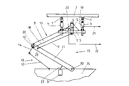
The current collector 15 schematically depicted in Figure 1 is
used for lifting and pressing two collector shoes 1 against a
contact wire 2. The collector shoes 1 are supported by end-side
spring-loaded legs on a rocker 5. In total, two spring-loaded
legs 4 are provided per each collector shoe 1. However, only one
spring-loaded leg per each collector shoe can be seen in Figure
1.
The rocket 5 is connected to a supporting piece 7 tilting about
a horizontal axis 6. The supporting piece 7 is rotatably
connected to the upper end of a pair of support arms 8 and 18.
Further, a guide bar 9 is rotatably linked to the supporting
piece 7. Both the pair of the support arms 8 and 18 and the
guide bar 9 are rotatably linked to a support arm 11. Thus,
altogether there is a four-bar chain called upper pantograph 10.
The support arm 11 is a part of a further four-bar chain. The
support arm 11 itself is connected to a motor coach 24 rotatably
about a horizontal axis 30. Further, a guide bar 13 is rotatably
connected to the motor coach 24. The guide bar 13 is rotatably
linked to an extension element 14 of the pair of the support
arms 8 and 18. This extension element 14 can be rotated about
the horizontal axis 28 together with the support arms 8 and 18.
The lower four-bar chain is also called lower pantograph 12. A
lifting device 3 is provided for raising the lower, first
support arm 11 in direction of arrow 23 about the first
horizontal axis 30. with raising the first support arm 11, the
pair of the second support arms 8 and 18 is also raised about
the second horizontal axis 28 due to the coupling of the lower
pantograph 12 with the upper pantograph 10. Here, the extension
element 14 of the pair of the second support arms 8 and 18 is
not rigidly connected with the second support arms 8 and 18, as
it is apparent from the detail according Figure 2. The support
arms 8 and 18 are rather connected with the extension element 14
via torsional actuators 16 and 17. The torsional actuators 16
and 17 have a relative high torsional stiffness. However, it is
2189410
at the same time possible to purposefully apply torques between
the extension element 14 and the second support arms via the
torsional actuators 16 and 17 also. To this end, the torsional
actuators 16 and 17 are controlled by a control means 25. The
control means 25 operates in dependence on a force signal 21
from a force sensor 19, which measures, beneath one of the
collector shoes 1, the contact force of said collector shoe
against the contact wire 2, and on a acceleration signal 22 from
a acceleration sensor 20 at the upper end of the support arm 8.
Additionally, further displacement, force and/or acceleration
sensors can be arranged on the current collector, whose signals
are taken into account by the control means. The control means
25 controls the torsional actuators 16 and 17 in such a way that
the contact force of the collector shoes 1 against the contact
wire 2 is kept constant to a extend as large as possible. To
this end, the stiffnesses of the support of the contact wire 2
by a contact wire suspension, which are varying over the
longitudinal extension of the contact wire 2, are to be
compensated. Further, dynamic excitations of the current
collector are to dampened, and aerodynamic influences of the
relative wind blowing against the current collector are to be
compensated.
From the detail according to Figure 2, bracing wires 26 and 27
are also apparent by which the pair of the second support arms
is braced to increase its stiffness. However, the torsional
actuators 16 and 17 can be controlled separately from each other
to compensate influences on the current collector which are
unsymmetrical with regard to the plane of symmetry of the
current collector. The guide bar 9 is connected to the support
arm 11 rotatably about the axis 29 drafted in Figure 2.
Figure 3 shows one possible construction of one of the torsional
actuators 17 between the extension element 14 and the second
support arm 18 in a longitudinal section along the second
2189410
horizontal axis 28. The torsional actuator 17 comprises a tube
section 31 of an anisotropic fibre compound material. The tube
section 31 is arranged coaxially with the second horizontal axis
28. The ends of the tube section 31 are rigidly connected to the
extension element 14 on one side and to the second support arm
18 on the other side. Therein, a common bearing bar 32 extends
through both the extension element 14 and the support arm 18 as
well as through the actuator 17 which is arranged in between. A
nut 33 is screwed on the bearing bar 32 which presses the second
support arm 18 against the extension element 14 via Belleville
springs 34. Herein, the tube section 31 arranged in between is
pre-stressed with pressure. A ring-shaped linear actuator 35 is
arranged in the annular space between the tube section 31 and
the bearing bar 32. The linear actuator 35 is supported on one
side on the extension element 14 and on the other side, via a
sliding ring 36, on the second support arm 18. Thus, with
operating the linear actuator 35 the tube section 31 is loaded
with pressure, which means that the pressure pre-stress applied
31 via the Belleville springs 34 is partly taken away. The
torsional forces associated with different pressure stress on
the tube section 31 are apparent from Figure 4. Figure 4 shows
the tube section 31 in a schematized side view. The tube section
31 is consisting of fibre compound material having a matrix 37
and fibres 38 embedded in the matrix 37. The fibres 38 are
arranged in parallel, and orientated spirally with regard to the
axis of the tube section 31. A longitudinal distortion of the
tube section 31 occurs with a variation of a pressure pre-stress
on the tube section 31 in direction of the arrows 39. Due to the
anisotropic construction of the fibre compound material, this
longitudinal distortion comes along with a relative twisting of
the two ends of the tube section 31, which is indicated by
symbols 40 and 41. In this way, torsional forces can be applied
between the extension element 14 and the second support arm 18
2189410
11
by the linear actuator 35 according to Figure 3. Such a
correlation between an axial force application, i. e. a
distortion, and a torsion is, for example, also observed with a
helical spring.
The embodiment of the torsional actuator 17 which is depicted in
Figure 5 in a longitl]~l n~l section along the second horizontal
axis 28 is based on another principle of operation. Here, two
slit-open tube sections 42 and 43, which are arranged in each
other and coaxially with the second horizontal axis 28, are
provided between the extension element 14 and the second support
arm 18. The slots 44 and 45 of the two tube sections 42 and 43
extend parallel to the axis 28, and oppose each other with
regard to the axis 28. In the region opposing its slot 44 or 45,
respectively, each of the tube sections 42 and 43 iS rigidly
attached at one end to the extension element 14 and at the
opposing end to the support arm 18. Therein the inner slit-open
tube section 43 lies, with a tension directed radially inwards,
against a guide bush 46, which is formed partly by the extension
element 14 and partly by the support arm 18; while the outer
slit-open tube section lies, with a tension directed radially
outwards, against a guide bushing 47. Due to this support the
coaxial orientation of the two slit-open tube sections 42 and 43
is stabilized. However, it is at the same time also possible to
generate a torque about the axis 28 between the extension
element 14 and the support arm 18 by means of the slit-open tube
sections 42 and 43. For a corresponding relative movement, a
sliding ring 68 iS provided between the two parts of the guiding
bush 46.
How the torsion between both ends of the torsional actuator 17
is generated, is apparent from Figures 6 and 7. There, both
slit-open tube sections are depicted in a longitudinal section
and a top view. Two linear actuators 49 and 50 act upon the tube
sections 42 and 43. The points of action are located in axial
12 2189410
and tangential edge regions of the respective tube section. A
vault distortion of the tube sections 42 and 43 which is
indicated by symbols 40 and 41 in Figure 7 can be initiated by
means of the actuators 49 and 50, the vault distortion leading
to a relative twisting of the two end regions of the tube
sections in direction of the arrows 51 and 52, respectively.
According to Figure 6, each of the linear actuators 49 and 50
acts upon the slit-open tube sections 42 and 43 in axially
opposing points. Therein, the points are not in the absolute
tangential end regions of the respective tube section. The
embodiment according to Figures 8 to 10 is different. There, a
single ring-shaped linear actuator 53 is provided. This linear
actuator 53 acts upon both slit-open tube sections 42 and 43 via
sliding rings 54 and 55. The points of action are located in the
absolute axial and tangential edge regions of the tube section,
i. e. at their ends in the proximity of the slots 44 or 45,
respectively. The sliding rings 54 and 55 ensure that the linear
actuator 53 is only stressed in operation direction. In the
embodiment according to Figures 6 and 7, this can be achieved by
rotatably connecting the linear actuators 49 and 50 to the two
tube sections. The effect of the vault distortion applied to the
tube sections 42 and 43 via the ring-shaped linear actuator 53
is apparent from Figure 10, in which the arrows 51 indicate the
rotation direction of the upper end of the torsional actuator 17
with the torsion initiated.
2189410
13
L I S T O F R E F E R E N C E S I G N S
1 - collector shoe 11 - first support arm
2 - contact wire 12 - lower pantograph
3 - lifting device 13 - guide bar
4 - spring-loaded leg 14 - extension element
5 - rocker 15 - current collector
6 - axis 16 - torsional actuator
7 - supporting piece 17 - torsional actuator
8 - second support arm 18 - second support arm
9 - guide bar 19 - force sensor
10 - upper pantograph 20 - acceleration sensor
21 - force signal 31 - tube section
22 - acceleration signal 32 - bearing bar
23 - arrow 33 - nut
24 - motor coach 34 - Belleville spring
25 - control means 35 - linear actuator
26 - bracing wire 36 - sliding ring
27 - bracing wire 37 - matrix
28 - second horizontal axis 38 - fibre
29 - axis 39 - arrow
30 - first horizontal axis 40 - symbol
41 - symbol 51 - arrow
42 - tube section 52 - arrow
43 - tube section 53 - linear actuator
44 - slot 54 - sliding ring
45 - slot 55 - sliding ring
46 - guide bush
47 - guide bushing
48 - s l iding ring
49 - linear actuator
50 - linear actuator