Language selection

Search

Patent 2189464 Summary

Third-party information liability

Some of the information on this Web page has been provided by external sources. The Government of Canada is not responsible for the accuracy, reliability or currency of the information supplied by external sources. Users wishing to rely upon this information should consult directly with the source of the information. Content provided by external sources is not subject to official languages, privacy and accessibility requirements.

Claims and Abstract availability

Any discrepancies in the text and image of the Claims and Abstract are due to differing posting times. Text of the Claims and Abstract are posted:

  • At the time the application is open to public inspection;
  • At the time of issue of the patent (grant).
(12) Patent: (11) CA 2189464
(54) English Title: TRANSMISSION CONTROL LEVER WITH RETURN TO NEUTRAL FUNCTION
(54) French Title: LEVIER DE COMMANDE DE CHANGEMENT DE VITESSE AVEC RETOUR AUTOMATIQUE AU POINT NEUTRE
Status: Expired and beyond the Period of Reversal
Bibliographic Data
(51) International Patent Classification (IPC):
  • B62D 6/00 (2006.01)
  • F16H 59/02 (2006.01)
  • F16H 59/08 (2006.01)
(72) Inventors :
  • BREMNER, RONALD DEAN (United States of America)
  • NEWENDORP, BRUCE CRAIG (United States of America)
  • D'ALESSANDRO, PATRICIA M. (United States of America)
(73) Owners :
  • DEERE & COMPANY
(71) Applicants :
  • DEERE & COMPANY (United States of America)
(74) Agent: BORDEN LADNER GERVAIS LLP
(74) Associate agent:
(45) Issued: 1999-08-10
(22) Filed Date: 1996-11-01
(41) Open to Public Inspection: 1997-05-15
Examination requested: 1996-11-01
Availability of licence: N/A
Dedicated to the Public: N/A
(25) Language of filing: English

Patent Cooperation Treaty (PCT): No

(30) Application Priority Data:
Application No. Country/Territory Date
08/557,590 (United States of America) 1995-11-14

Abstracts

English Abstract


A control system for controlling multi-ratio vehicle
transmission includes a speed select lever movable from a park
position to selected gear ratio positions and a directional
control lever having forward, neutral and reverse positions.
A system is provided to cause the directional control lever to
automatically move to its neutral position when the shift
control lever is moved to its park position.


Claims

Note: Claims are shown in the official language in which they were submitted.

The embodiments of the invention in which an exclusive
property or privilege is claimed are defined as follows:
1. In a control system for controlling multi-ratio
vehicle transmission, the control system having a first
control lever having a park position associated with a
condition wherein movement of the vehicle is prevented, and
having a directional control lever having a forward position
associated with a condition of the transmission which moves
the vehicle in a forward direction, a neutral position
associated with a neutral condition of the transmission, and a
reverse position associated with a condition of the
transmission which moves the vehicle in a reverse direction,
characterized by:
a detent mechanism engagable with the directional control
lever, the detent mechanism having a detent position wherein
the directional control lever is held in its forward or its
reverse position, and the decent mechanism having a release
position wherein the directional control lever is moved to its
neutral position; and
means coupled to the first lever for moving the detent
mechanism to its release position when the first lever is
moved to its park position.
2. The invention of claim 1, wherein:
the detent mechanism comprises an electrically operated
actuator which is coupled to a source of electrical power and
which automatically moves to the release position when the
source of power is disconnected from the actuator.
3. The invention of claim 1, wherein:
the first lever comprises a speed select lever having a
plurality of gear positions associated with selected gear
ratios of the transmission.
4. In a control system for controlling multi-ratio
vehicle transmission, the control system having a first lever
having a park position associated with a condition wherein
movement of the vehicle is prevented, and having a directional
control lever having a forward position associated with a
condition of the transmission which moves the vehicle in a

forward direction, a neutral position associated with a
neutral condition of the transmission, and a reverse position
associated with a condition of the transmission which moves
the vehicle in a reverse direction, characterized by:
means for generating a park signal when the first lever
is in its park position; and
means for automatically moving the directional control
lever to its neutral position in response to the park signal,
said means for automatically moving comprising:
a centering spring coupled to the directional control
lever and biased to urge it towards its neutral position;
a detent member engagable with the directional control
lever, the detent member having a detent position wherein the
directional control lever is held in its forward or its
reverse position, and the detent member having a release
position wherein the directional control lever is allowed to
be returned to its neutral position by the centering spring;
a detent spring coupled to the detent member and biased
to move the detent member to its release position;
an actuator coupled to the detent member and energizable
to move the detent member to its detent position against the
bias of the detent spring;
a source of energy; and
a switch connected between the energy source and the
actuator, the switch also being coupled to the first lever so
that the switch disconnects the actuator from the energy
source when the first lever is in its park position.
5. The invention of claim 4, wherein:
the first lever comprises a shift control lever having a
plurality of gear positions associated with selected gear
ratios of the transmission.

Description

Note: Descriptions are shown in the official language in which they were submitted.


21 P.9464
TRANSMISSION CONTROL LEVER WITH RETURN TO NEUTRAL FUNCTION
Background of the Invention
This invention relates to a vehicle transmission control
system for a multiple gear ratio transmission, in particular a
transmission control system having a shift or speed select
lever and a forward-neutral-reverse or directional control
lever.
It is known to provide vehicles with a transmission
control system having a speed select or shift lever for
selecting transmission gear ratios and a directional control
lever with forward, neutral and reverse positions. With such
a system the operator is not always required to move the
directional control lever into its neutral position when park
is engaged. If such an operator leaves and re-enters the
vehicle, or if a new operator enters the vehicle, the lever
may be moved out of park and into a selected gear position
without the operator being aware of the position of the
directional control lever. As a result, the vehicle may start
moving in a direction not expected or not intended by the
operator.
Summary of the Invention
An object of the present invention is to provide a
transmission control system which reduces the chances of the
vehicle moving in a direction not expected or not intended by
the operator.
These and other objects are achieved by the present
invention wherein a control system for controlling multi-ratio
vehicle transmission includes a speed select lever movable
from a park position to selected gear ratio positions and a
directional control lever having forward, neutral and reverse
positions. A system is provided to cause the directional
control lever to automatically move to its neutral position
when the shift control lever is moved to its park position.

~1 89464
Brief Description of the Drawings
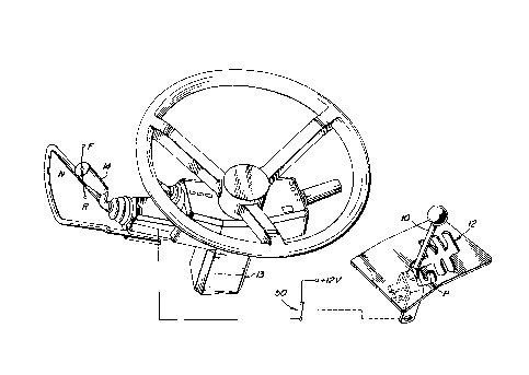
FIG. 1 is a partially schematic illustration of a lever
control system according to the present invention.
FIG. 2 is a perspective view of a forward-neutral-reverse
lever mounted on a vehicle steering column.
Detailed Description
As shown in FIG. 1, a shift or range lever 10 is moveable
in a gate 12 to various positions, including a park position
P, to control a conventional vehicle transmission (not shown),
such as a John Deere Power Quad 4 speed transmission. Such a
shift lever is preferably mounted in a console (not shown) in
a vehicle operator compartment. A conventional directional
control lever 14 is operatively coupled to the transmission
(not shown) and is movable to a forward position, F,
associated with a condition of the transmission (not shown)
which moves the vehicle in a forward direction, a neutral
position associated with a neutral condition of the
transmission (not shown), and a reverse position associated
with a condition of the transmission (not shown) which moves
the vehicle in a reverse direction. The neutral position N is
located between the forward F and reverse R positions. Such a
directional control lever 14 is preferably mounted on the
steering column 13 in a vehicle operator compartment.
Referring now to Fig. 2, the lever 14 is connected to a
rotor arm 16 which rotates about a pin 18. A pair of
centering springs 20, 22 are biased to urge the lever 14 to
its neutral position. A detent sleeve 24 is mounted on the
end of arm 16. A detent roller 26 is mounted in the end of
sleeve 24 and is biased outwardly thereof by a detent roller
spring (not shown) which is enclosed within the sleeve 24.
The roller 26 is engagable with a detent slider mechanism 30
which includes a detent slide 32 mounted on a shaft 33 of a
linear actuator 34, such as a linear solenoid. The slide 32
includes a base 36 upon which are formed three curved detent
grooves 38, 40 and 42 and a detent slot 44. The slide 32 has
a detent position wherein detent roller 26 is engagable with

21 8~464
the detent grooves 38-40 and a non-detent position wherein the
roller 26 free to move across the slot 44. When the solenoid
34 is energized and extended, and the slide 32 will be in the
detent position shown in Fig. 2. The slide 32 is preferably
5 biased to the right, viewing Fig. 2, towards its retracted
non-detent position by a spring (not shown) which is internal
to the solenoid 34.
As best seen in Fig. 1, a normally closed park switch 50
is connected electrically between a 12 volt source, +12v, such
as the vehicle battery, and the solenoid 34. When the switch
50 is closed, the solenoid 34 is energized and extended, and
the slide 32 will be in the detent position shown in Fig. 2.
The switch 50 is operatively coupled to the shift lever 10 so
that it is opened only when the shift lever 10 is moved to its
15 park position P. As a result, when the shift lever 10 is
moved to its park position, the switch 50 opens, the solenoid
34 is de-energized and the slide 32 moves to the right and
moves the detent grooves 38-42 out of engagement with the
detent roller 26. The centering springs 20 and 22 will then
20 return the directional control lever 14 to its neutral
position. This prevents the operator from unintentionally
leaving the lever 14 in forward or reverse after the shift
lever 10 is placed in park. Also, because the solenoid 34
must be energized for the slide 32 to be in its detent
25 position, if a power failure occurs, the lever 14 will be
returned to the neutral position.
While the invention has been described in conjunction
with a specific embodiment, it is to be understood that many
alternatives, modifications and variations will be apparent to
30 those skilled in the art in light of the foregoing
description. In this regard, the present invention could be
used in connection with any set of transmission controls where
the park engagement control is on a different lever than the
direction control. For example, there are some tractors which
35 have a park control lever which is separate from any other
control. Other tractors use a park brake instead of a park
pawl. This invention would apply to both such situations.

21 89464
Accordingly, this invention is intended to embrace all such
alternatives, modifications and variations which fall within
the spirit and scope of the appended claims.

Representative Drawing
A single figure which represents the drawing illustrating the invention.
Administrative Status

2024-08-01:As part of the Next Generation Patents (NGP) transition, the Canadian Patents Database (CPD) now contains a more detailed Event History, which replicates the Event Log of our new back-office solution.

Please note that "Inactive:" events refers to events no longer in use in our new back-office solution.

For a clearer understanding of the status of the application/patent presented on this page, the site Disclaimer , as well as the definitions for Patent , Event History , Maintenance Fee  and Payment History  should be consulted.

Event History

Description Date
Inactive: IPC deactivated 2011-07-29
Inactive: First IPC derived 2006-03-12
Inactive: IPC from MCD 2006-03-12
Time Limit for Reversal Expired 2002-11-01
Letter Sent 2001-11-01
Grant by Issuance 1999-08-10
Inactive: Cover page published 1999-08-09
Inactive: Final fee received 1999-04-29
Pre-grant 1999-04-29
Notice of Allowance is Issued 1998-12-07
Letter Sent 1998-12-07
Notice of Allowance is Issued 1998-12-07
Inactive: Status info is complete as of Log entry date 1998-12-03
Inactive: Application prosecuted on TS as of Log entry date 1998-12-03
Inactive: Approved for allowance (AFA) 1998-11-24
Application Published (Open to Public Inspection) 1997-05-15
All Requirements for Examination Determined Compliant 1996-11-01
Request for Examination Requirements Determined Compliant 1996-11-01

Abandonment History

There is no abandonment history.

Maintenance Fee

The last payment was received on 1998-10-30

Note : If the full payment has not been received on or before the date indicated, a further fee may be required which may be one of the following

  • the reinstatement fee;
  • the late payment fee; or
  • additional fee to reverse deemed expiry.

Please refer to the CIPO Patent Fees web page to see all current fee amounts.

Fee History

Fee Type Anniversary Year Due Date Paid Date
MF (application, 2nd anniv.) - standard 02 1998-11-02 1998-10-30
Final fee - standard 1999-04-29
MF (patent, 3rd anniv.) - standard 1999-11-01 1999-10-29
MF (patent, 4th anniv.) - standard 2000-11-01 2000-10-31
Owners on Record

Note: Records showing the ownership history in alphabetical order.

Current Owners on Record
DEERE & COMPANY
Past Owners on Record
BRUCE CRAIG NEWENDORP
PATRICIA M. D'ALESSANDRO
RONALD DEAN BREMNER
Past Owners that do not appear in the "Owners on Record" listing will appear in other documentation within the application.
Documents

To view selected files, please enter reCAPTCHA code :


To view images, click a link in the Document Description column. To download the documents, select one or more checkboxes in the first column and then click the "Download Selected in PDF format (Zip Archive)" or the "Download Selected as Single PDF" button.

List of published and non-published patent-specific documents on the CPD .

If you have any difficulty accessing content, you can call the Client Service Centre at 1-866-997-1936 or send them an e-mail at CIPO Client Service Centre.


Document
Description 
Date
(yyyy-mm-dd) 
Number of pages   Size of Image (KB) 
Description 1997-03-25 4 151
Claims 1997-03-25 2 90
Drawings 1997-03-25 2 53
Abstract 1997-03-25 1 13
Cover Page 1997-03-25 1 18
Claims 1998-11-10 2 93
Cover Page 1999-08-03 1 41
Cover Page 1998-07-07 1 18
Representative drawing 1998-05-22 1 32
Representative drawing 1999-08-03 1 17
Reminder of maintenance fee due 1998-07-06 1 115
Commissioner's Notice - Application Found Allowable 1998-12-07 1 163
Maintenance Fee Notice 2001-11-29 1 178
Correspondence 1999-04-29 1 27
Correspondence 1996-11-28 1 48