Language selection

Search

Patent 2189744 Summary

Third-party information liability

Some of the information on this Web page has been provided by external sources. The Government of Canada is not responsible for the accuracy, reliability or currency of the information supplied by external sources. Users wishing to rely upon this information should consult directly with the source of the information. Content provided by external sources is not subject to official languages, privacy and accessibility requirements.

Claims and Abstract availability

Any discrepancies in the text and image of the Claims and Abstract are due to differing posting times. Text of the Claims and Abstract are posted:

  • At the time the application is open to public inspection;
  • At the time of issue of the patent (grant).
(12) Patent: (11) CA 2189744
(54) English Title: BONE PLATE
(54) French Title: PLAQUE POUR OSTEOSYNTHESE
Status: Term Expired - Post Grant Beyond Limit
Bibliographic Data
(51) International Patent Classification (IPC):
  • A61B 17/80 (2006.01)
(72) Inventors :
  • TALOS, GILBERT (Switzerland)
  • SCHMOKER, ROLAND (Switzerland)
(73) Owners :
  • SYNTHES (U.S.A.)
  • SYNTHES USA, LLC
(71) Applicants :
  • SYNTHES (U.S.A.) (United States of America)
  • SYNTHES USA, LLC (United States of America)
(74) Agent: MARKS & CLERK
(74) Associate agent:
(45) Issued: 2003-09-16
(86) PCT Filing Date: 1995-03-27
(87) Open to Public Inspection: 1996-10-03
Examination requested: 2000-07-25
Availability of licence: N/A
Dedicated to the Public: N/A
(25) Language of filing: English

Patent Cooperation Treaty (PCT): Yes
(86) PCT Filing Number: PCT/CH1995/000065
(87) International Publication Number: WO 1996029948
(85) National Entry: 1996-11-06

(30) Application Priority Data: None

Abstracts

English Abstract


The invention concerns a bone plate which is provided
with a plurality of holes, disposed in the direction of the
longitudinal axis of the plate, for accommodating bone
screws. The diameter (DL) of at least one hole - measured in
the direction of the longitudinal axis of the plate - is
larger than the diameter (DQ) of this hole measured
perpendicular to the longitudinal axis of the plate. At
least one of these holes with a smaller diameter (DQ)
perpendicular to the longitudinal axis of the plate comprises
in the region of this diameter (DQ) a partial thread for
receiving a bone screw with a threaded head.


French Abstract

L'invention concerne une plaque pour ostéosynthèse comportant plusieurs trous (2) pratiqués dans le sens de l'axe longitudinal de la plaque (1) et destinés à recevoir des vis pour fracture osseuse. Le diamètre DL d'au moins un trou (2) (mesuré en direction de l'axe longitudinal de la plaque (1)) est supérieur au diamètre DQ dudit trou (2) (mesuré perpendiculairement à l'axe longitudinal de la plaque (1)). Au moins un de ces trous (2) dont le diamètre DQ est inférieur, perpendiculairement à l'axe longitudinal de la plaque (1), comporte un filetage (3) partiel dans la zone dudit diamètre DQ, pour recevoir une vis pour fracture osseuse à tête filetée.

Claims

Note: Claims are shown in the official language in which they were submitted.

7
The embodiments of the invention in which an exclusive
property or privilege is claimed are defined as follows:
1. A bone plate comprising:
an elongated plate, defining a longitudinal axis along
its length, having an upper surface;
a lower surface for application to a bone; and
a plurality of elongated holes arranged along the length
of the plate for receiving bone screws, said elongated
holes being oblong in shape and having a major axis DL and a
minor axis DQ, with DL being greater than DQ;
wherein at least one of said elongated holes includes
partial threaded portions arranged on an inner wall of the
elongated hole, and is configured for seating a bone screw
having a threaded head.
2. The bone plate of claim 1, wherein each elongated hole
has a lower part which extends to the lower surface of the
plate, and an upper part which extends to the upper surface
of the plate, and the partial threaded portion is
positioned in the lower part of the elongated hole.
3. The bone plate of claim 2, wherein the lower part of
said at least one elongated hole includes a flared surface,
which extends outwardly to the lower surface of the bone
plate.
4. The bone plate of claim 3, wherein the partial
threaded portions extend around opposing portions of the

8
inner wall in an area of the minor axis, and the lower
flared surface extends outwardly adjacent to the partial
threaded portions.
5. The bone plate of claim 3 or 4, wherein said lower
flared surface is conically shaped.
6. The bone plate of any one of claims 1 to 5, wherein
DL/DQ is within the range of 1.01 to 3.
7. The bone plate of claim 6, wherein DL/DQ is within the
range of 1.1 to 1.5.
8. The bone plate of any one of claims 1 to 7, wherein
the major axis of at least one of said elongated holes is
positioned along the longitudinal axis of the plate.
9. The bone plate of any one of claims 1 to 8, wherein
the lower surface has a curved shape for contacting a bone.
10. The bone plate of any one of claims 1 to 9, wherein
said at least one elongated hole further comprises an
outwardly flared countersink surface adjacent the upper
surface for slidingly receiving a bone screw having a
spherical head.
11. The bone plate of claim 10, wherein the outwardly
flared countersink surface is shaped and configured for
mating engagement with the bone screw.

9
12. The bone plate of claim 10 or 11, wherein the
outwardly flared countersink surface has an angle relative
to the longitudinal axis of the plate which is sufficient
to produce a ramping effect for engagement with a bone
screw.
13. The bone plate of claim 12, wherein the outwardly
flared countersink surface has an angle of 57°.
14. A method for compressing a bone using the bone plate
defined in any one of claims 10 to 13, the method
comprising the steps of:
positioning said bone plate on a surface, the bone plate
including at least one elongated hole having an outwardly
flared countersink surface;
inserting a bone screw, having a spherical head, into at
least one elongated hole, at one end of said hole; and
screwing said bone screw into the surface so that, as the
spherical head of the screw contacts the outwardly flared
countersink surface of the hole, the spherical head of the
screw ramps downwardly along the flared surface to move the
plate to generate compression.

Description

Note: Descriptions are shown in the official language in which they were submitted.


CA 02189744 2001-10-31
1
BONE PLATE
The invention concerns a bone plate for stabilizing
and/or compressing a bone.
A bone plate is known from French patent document 742,618
wherein circular boreholes in the plate slant relative to
a normal to the plate and are fitted with inside threads.
These boreholes accept bone screws fitted with a second
threaded portion which is widened compared to the
conventional threaded screw shank segment and corresponds
to the inside thread of the plate boreholes. Because of
the slant of the plate boreholes, the bone screws also
can be anchored at a slant, determined by said boreholes,
into the bone.
The known bone plate incurs the drawback that the slant
of the bone screws cannot be selected at will but instead
is predetermined by the slant of the boreholes and their
inside thread.
The object of the invention is palliation and to create a
bone plate of which the boreholes are designed
selectively to make possible two different kinds of screw
anchorings. In a first embodiment, a bone screw with a
spherical head may be screwed into an elongated slot of
the plate within a wide and selectable range at an angle
to the plate normal into the bone. By tilting the

CA 02189744 2001-10-31
2
countersink of the plate boreholes, furthermore a
compressive effect is made possible.
In a second embodiment, a bone screw with a head thread
and in the form of a bracing screw can be vertically and
rigidly screwed into the plate at the partial inside
thread of the elongated slot.
According to the invention, there is provided a bone
plate comprising an elongated plate defining a
longitudinal axis along its length, having an upper
surface, a lower surface for application to a bone, and a
plurality of elongated holes arranged along the length of
the plate for receiving bone screws. The elongated holes
are oblong in shape and have a major axis DL and a minor
axis DQ, with DL being greater than DQ. At least one of
said elongated holes includes partial threaded portions
arranged on an inner wall of the elongated hole, and is
configured for seating a bone screw having a threaded
head.
Preferably each elongated hole has a lower part which
extends to the lower surface of the plate, and an upper
part which extends to the upper surface of the plate, and
the partial threaded portion is positioned in the lower
part of the elongated hole. Further the lower part of
said at least one elongated hole can include a flared
surface, which extends outwardly to the lower surface of

CA 02189744 2001-10-31
2a
the bone plate. Conveniently, the partial threaded
portions extend around opposing portions of the inner
wall in an area of the minor axis, and the lower flared
surface extends outwardly adjacent to the partial
threaded portions.
Optionally, the lower flared surface is conically shaped.
The at least one elongated hole can further comprises an
outwardly flared countersink surface adjacent the upper
surface for slidingly receiving a bone screw having a
spherical head, preferably wherein the outwardly flared
countersink surface is shaped and configured for mating
engagement with the bone screw. Advantageously, the
outwardly flared countersink surface has an angle
relative to the longitudinal axis of the plate which is
sufficient to produce a ramping effect for engagement
with a bone screw. Preferably the outwardly flared
countersink surface has an angle of 57°.
Preferably, the ratio DL/DQ is within the range of 1.01 to
3, more preferably within the range of 1.1 to 1.5.
Advantageously, the major axis of at least one of said
elongated holes is positioned along the longitudinal axis
of the plate. Conveniently, the lower surface has a
curved shape for contacting a bone.
According to the invention, there is also provided a
method for compressing a bone using the bone plate

CA 02189744 2001-10-31
2b
disclosed herein. The method comprises the steps of
positioning said bone plate on a surface, the bone plate
including at least one elongated hole having an outwardly
flared countersink surface inserting a bone screw, having
a spherical head, into at least one elongated hole, at
one end of said hole, and screwing said bone screw into
the surface so that, as the spherical head of the screw
contacts the outwardly flared countersink surface of the
hole, the spherical head of the screw ramps downwardly
along the flared surface to move the plate to generate
compression.
Essentially, the advantages offered by the invention are
that the bone plate of this invention are ubiquitously
applicable in the most diverse cases [fixation,
compression, employment as fixateur interne (internal
affixer) in the sense of a bracing screw), but especially
in the maxillofacial field requiring three-dimensional
matching.
The invention offers also the following advantages:
-- compatibility with conventional Kortikalis screws,
-- variable angular orientation of the bone screws in the
plate boreholes
-- problem-free removal of bone screws even in the case
of intra-oral access,

218974.
3
-- possibility of new operation using a new plate,
-- screw head affixation in the plate borehole using bone screws
of conventional diameter, and
-- achieving compression using screws with spherical heads.
The invention and further embodiments of this invention are
elucidated below in relation to partly diagrammatic drawings of
an illustrative embodiment.
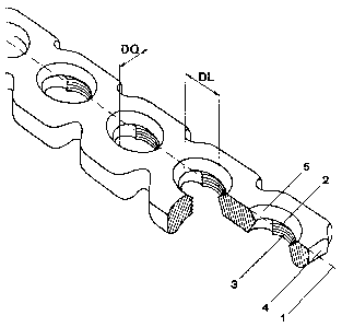
Fig. 7. is a partial perspective of a bone plate of the
invention,
Fig. 2 is a partial top view of the bone plate of the ,invention,
Fig. 3 is a partial longitudinal section of the bone plate along
line III-III of Fig. 2,
Fig. 4 is a cross-section orthogonal to the bone-plate
longitudinal direction along line IV-IV of Fig. 2,
Fig. 5 is a partial longitudinal section of a bone plate of the
invention with a double-threaded bone screw which is screwed-in
perpendicularly,

2~8974~
Fig. 6 is a partial longitudinal section of a bone plate of the
invention with a bone screw passing through the plate
perpendicularly or at a slant, said-bone screw comprising a
spherical head and serving as a non-compressive affixation
screw,
Fig. 7 is a cross-section perpendicular to the longitudinal
section of Fig. 6 and located in the hole area of the bone
plate, and
Fig. 8 is a partial longitudinal section of a bone plate of the
invention through which passes a perpendicular bone screw with a
spherical head and serving as a compressive affixation screw.
The bone plate shown in Fig. 1 comprises several holes 2 to
receive diverse types of bone screws 6, 7 (shown in Figs. 5, 6)
with which to affix the bone plate to the bone.
As shown in detail in Figs. 2-4, the holes 2 are designed to be
so-called elongated slots, that is, when measured in the
direction of the plate longitudinal axis, the diameter DL is
larger than the diameter DQ perpendicular to the plate
longitudinal axis 1.
As shown in Fig. 4, the lower part of the hole 2 facing the bone
application surface is approximately circular in the direction
transverse to the plate and, as shown in Fig. 3, it flares
approximately sonically in the plate longitudinal direction

~~~97~4
i
toward the bone application surface 4. An inside thread is in
the circular segment of the hole 2 and, because of design
constraints, runs only in the lateral part of the plate over an
angular range of about 60° to 179', preferably about 90° to
150'.
As shown in Fig. 5, this partial inside thread is used to
receive a bone screw 6 with a thread-head 9. By screwing the
outside thread of the thread-head 9 into the corresponding and
partial inside thread 3, rigid anchoring of bone screw 6 into
the plate is achieved. Such screwed-in bone screw 6 serves as a
bracing screw.
The upper part of hole 2 away from bone contact surface 4 is
oval and comprises a conical flaring area which, as shown in
Figs. 6, 7, slidingly receives a bone screw 7 with a spherical
head 8. The expression °bone application surface° ~ denotes the
plate surface which substantially directly contacts the bone.
Similarly to Figs. 6; 7, Fig. 8 shows a bone plate fitted with a
bone screw 7 comprising a spherical head 8, said plate, as
indicated by the arrow 10, being able to generate compression.
For that purpose the conically flaring area 5 of the hole 2 (as
shown in Fig. 3j, is machined by a spherical or bevelling miller
at an angle of 57° relative to the plate longitudinal axis 1,
whereby the elongated slot so produced acts like a ramp for the
bone screw 7.

~1897~4
6
The special geometry of the hole 2 allows selective use of
various types of bone screws 6, 7 on one and the same bone
plate.

Representative Drawing
A single figure which represents the drawing illustrating the invention.
Administrative Status

2024-08-01:As part of the Next Generation Patents (NGP) transition, the Canadian Patents Database (CPD) now contains a more detailed Event History, which replicates the Event Log of our new back-office solution.

Please note that "Inactive:" events refers to events no longer in use in our new back-office solution.

For a clearer understanding of the status of the application/patent presented on this page, the site Disclaimer , as well as the definitions for Patent , Event History , Maintenance Fee  and Payment History  should be consulted.

Event History

Description Date
Inactive: Expired (new Act pat) 2015-03-27
Letter Sent 2009-05-01
Inactive: Late MF processed 2004-05-05
Grant by Issuance 2003-09-16
Inactive: Cover page published 2003-09-15
Pre-grant 2003-06-23
Inactive: Final fee received 2003-06-23
Notice of Allowance is Issued 2003-04-28
Letter Sent 2003-04-28
Inactive: Approved for allowance (AFA) 2003-04-12
Amendment Received - Voluntary Amendment 2001-10-31
Letter Sent 2000-08-03
Inactive: Status info is complete as of Log entry date 2000-08-03
Inactive: Application prosecuted on TS as of Log entry date 2000-08-03
All Requirements for Examination Determined Compliant 2000-07-25
Request for Examination Requirements Determined Compliant 2000-07-25
Letter Sent 1997-08-19
Application Published (Open to Public Inspection) 1996-10-03

Abandonment History

There is no abandonment history.

Maintenance Fee

The last payment was received on 2003-02-28

Note : If the full payment has not been received on or before the date indicated, a further fee may be required which may be one of the following

  • the reinstatement fee;
  • the late payment fee; or
  • additional fee to reverse deemed expiry.

Please refer to the CIPO Patent Fees web page to see all current fee amounts.

Owners on Record

Note: Records showing the ownership history in alphabetical order.

Current Owners on Record
SYNTHES (U.S.A.)
SYNTHES USA, LLC
Past Owners on Record
GILBERT TALOS
ROLAND SCHMOKER
Past Owners that do not appear in the "Owners on Record" listing will appear in other documentation within the application.
Documents

To view selected files, please enter reCAPTCHA code :


To view images, click a link in the Document Description column. To download the documents, select one or more checkboxes in the first column and then click the "Download Selected in PDF format (Zip Archive)" or the "Download Selected as Single PDF" button.

List of published and non-published patent-specific documents on the CPD .

If you have any difficulty accessing content, you can call the Client Service Centre at 1-866-997-1936 or send them an e-mail at CIPO Client Service Centre.


Document
Description 
Date
(yyyy-mm-dd) 
Number of pages   Size of Image (KB) 
Representative drawing 1999-06-10 1 12
Representative drawing 2003-02-14 1 9
Abstract 2003-04-22 1 18
Abstract 2003-08-14 1 18
Cover Page 2003-08-22 1 37
Drawings 2003-09-15 4 59
Description 2003-09-15 8 226
Abstract 2003-09-15 1 18
Cover Page 1997-03-25 1 13
Abstract 1996-10-03 1 18
Description 1996-10-03 6 158
Claims 1996-10-03 1 28
Drawings 1996-10-03 4 59
Description 2001-10-31 8 226
Claims 2001-10-31 3 85
Courtesy - Certificate of registration (related document(s)) 1997-08-19 1 118
Acknowledgement of Request for Examination 2000-08-03 1 177
Commissioner's Notice - Application Found Allowable 2003-04-28 1 160
Late Payment Acknowledgement 2004-05-18 1 166
PCT 1996-11-06 19 653
Correspondence 1997-02-25 1 31
Correspondence 2003-06-23 1 31
Fees 1997-01-20 1 64