Note: Descriptions are shown in the official language in which they were submitted.
WO 95/31344 218 9 7 5 5 PCTIUS95/06300
WHEEL TRIM AND LUG PUT BETERTIOF SYSTBZi
TECHNICAL FIELD
This invention generally relates to lug nuts used to
retain motor vehicle wheels on vehicle axle hubs, and deals more
particularly with decorative type lug nuts which are retained on
wheel covers for the wheels.
BACKGROUND OF THE I1IVEDTI01f
Conventional wheel covers are typically retained on
motor vehicle wheels by spring clips engaging an outer flange of
the wheel or some other convenient location on the wheel.
Severe wheel impacts have been known to dislodge wheel covers so
retained from the wheels and of course, this form of retainment
allows the wheel covers to be easily stolen.
Another method of retaining the wheel covers on
vehicle wheels is exemplified by the wheel trim retention system
shown in U.S. Patent No. 4,998,780 issued March 12, 1991 to
Eshler, et al. The system shown in this patent employs
decorative plastic caps which pass through apertures in the
wheel cover and threadably engage an exterior thread on the lug
nuts which retain the vehicle wheel on the vehicle. The plastic
caps include a retainer to hold them on the wheel cover.
Although this arrangement retains the wheel cover on the vehicle
wheel, it is undesirable in that it increases the number of
parts required to mount the wheel and wheel cover. An
additional source of increased assembly complexity resides in
the fact that the 5 lug nuts must be tightened to a fairly high
torque level, and the plastic caps would be tightened to a
relatively low torque level, thus making the use of a single
torque control installation device unfeasible. Further,
additional assembly labor and time is required since both the
WO 95/31344 2 1 B 9 7 5 5 PCTIUS95/06300
lug nuts and the plastic lug nut caps must be installed in
separate operations. A further disadvantage of the Eshler et al
system is that in some cases, the decorative plastic caps may
loosen from the lug nuts because of jarring and vibration,
thereby resulting in rattling of the caps on the wheel cover, or
even loss of the wheel cover from the wheel.
It would therefore be desirable to provide a system
for positively retaining wheel covers on motor vehicle wheels
which require only one threading and torquing operation per lug
nut. It would also beneficial to reduce the number of parts
handled by a vehicle assembler at the wheel and wheel cover
mounting point on the assembly line. The present invention is
directed to satisfying these and other objectives.
SUP!lAYY OF TSB I11V$11TI01~
According to one aspect of the invention, a wheel
cover retention system for use with motor vehicle wheels
includes a wheel cover having a plurality of apertures
therethrough, a plurality of lug nuts for securing a wheel and
the wheel cover on the vehicle and means for retaining the lug
nuts on the wheel cover. The lug nuts are preferably made of
metal and include an outer, decorative end to which torque is
applied in order to thread the lug nuts onto the lugs of the
vehicle hub. The retaining means allows the lug nuts to be
preassembled onto the wheel cover so that only a single torquing
operation is required to mount both the wheel cover and the
wheel onto the axle hub of the vehicle. In one embodiment, a
retainer in the form of a ring which is either formed integral
with a central body portion of the nut, or sleeved over the body
portion, cooperates with a flange on the lug nut to capture a
face of the wheel cover therebetween, however, there is
sufficient radial clearance between the lug nut and the
apertures in the wheel cover to permit turning of the lug nut
-2-
WO 95/31344 21891 55 PCT/US95/06300
during torquing of the lug nuts onto the lugs of the axle hub.
Another embodiment of the retaining means employs an extension
of a decorative metal cap secured on the outer end of the lug
nut, wherein the cap extension extends through the wheel cover
apertures and engages the backside of the wheel cover to limit
axial displacement of the lug nuts away from the wheel. A still
further embodiment of the retaining means includes lateral,
blocking projections formed integral with the wheel cover which
engage a flange or other feature on the lug nut to likewise
limit outward axial displacement of the lug nuts on the wheel
cover, prior to their being torqued onto the lugs.
According to another aspect of the invention, a
method of mounting a wheel and a wheel cover on a motor vehicle
comprises passing a plurality of decorative lug nuts into
corresponding apertures in the wheel cover, retaining the lug
nuts on the wheel cover in order to form a subassembly,
positioning this subassembly in a mounting position over the
wheel such that the lug nuts are axially aligned with lugs on
the vehicle hub, and then torquing the lug nuts onto the lugs,
thereby simultaneously mounting the wheel cover and the wheel on
the vehicle hub.
BRIEF DBSCRIPTIOR OF THE DRAWIA6S
Figure 1 is a partial sectional view of a vehicle
wheel with a wheel cover mounted thereon by a first embodiment
of this invention.
Figure 2 is a partial sectional view of a vehicle
wheel with a wheel cover retained by a second embodiment of the
present invention.
Figure 3 is a partial sectional view of a vehicle
wheel with a wheel cover retained by a third embodiment of the
present invention.
-3-
WO 95/31344 2189755, PCT/US95/06300
Figure 4 is a partial sectional view of a vehicle
wheel with a vehicle wheel cover retained by a fourth embodiment
of the present invention.
Figure 5 is a partial sectional view of a vehicle
wheel with a vehicle wheel cover retained by a fifth embodiment
of the present invention.
Figure 6 is a partial sectional view of a vehicle
wheel with a vehicle wheel cover retained by a sixth embodiment
of the present invention.
DESCBIP?IOA OF THE PYEFBYltED ffiMDIMlrr
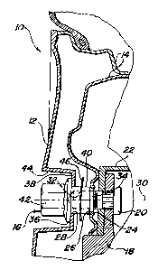
As shown in Figures 1-6, a wheel cover retention
system 10 holds a wheel cover 12 against a vehicle wheel 14 by
means of a plurality of lug nuts 16 which also hold the wheel 14
to an axle flange 18 of a vehicle (not shown).
The axle flange 18 has secured thereto a plurality
of circumferentially spaced lugs 20 which extend axially outward
and are threaded at their outer ends to threadably receive later
discussed lug nuts 16 thereon. A brake rotor 22 is shown on an
outboard side of the flange 18. The wheel 14 has a plurality of
circumferentially spaced apertures 24 accommodating the passage
of the lugs 20 therethrough. Each of the wheel apertures 24 has
a tapered seat 26. The wheel cover 12 is disposed over the
vehicle wheel 14 and includes a plurality of apertures 28
aligned with the lugs 20. The wheel cover 12 can be large
enough to either cover the entire wheel 14 or only a central
portion, or hub, of the wheel 14.
The lug nuts 16 extend through the wheel cover
apertures 28 and are each provided with a central threaded
aperture 32 on one end thereof which is coaxially aligned with
-4-
WO 95/31344 2 18 9 7 5 5 PCT/US95/06300
the central axis 30 of the nut 16. The threaded aperture 32
threadably receives the exterior or male threads on the lugs
20. A tapered seat portion 34 on one end of the lug nuts 16
engages the tapered seat 26 of the wheel apertures 24. A
circumferentially extending radial flange 36 of the lug nuts 16
overlaps and engages an outer seating surface 38 on the wheel
cover 12, which is shown as being recessed in a pocket 44 in the
embodiment of the wheel cover 12 illustrated in the drawings.
Extending between the flange 36 and the tapered seat
portion 34 of the lug nut 16, is a cylindrically shaped central
body portion 40. Axially extending from the flange 36 on the
outer end of the nut 16 are a plurality of wrench flats defining
a hex head 42 which permits application of wrenching torque to
the nut 16. The hex head 42 is substantially disposed within
the pocket 44. Alternatives to the hex head 42 include
conventional wheel locks (not shown) which could be engaged for
rotation by a key applied thereto which includes a hex head.
The lug nuts 16 may be of a one piece design, as
shown in Figures 1-4, which is provided with a decorative finish
such as chrome plating or anodizing. Alteraatively, the lug
nuts 16 may be of a two piece construction, as shown in Figures
and 6, wherein an outer decorative cap of stainless steel or
the like,. is disposed over the outer free end of the nut body
and is secured thereon by means of welding and/or crimping.
Examples of suitable two piece "capped" lug nut constructions
are disclosed in U.S. Patents Nos. 4,123,961; 4,018,133;
4,775,272; and 4,850,776, the entire disclosures of which are
incorporated by reference herein.
Retaining means in the form of a sheet metal push
nut 46 is disposed over and frictionally engages the body
portion 40 of the lug nut 16. The push nut 46, in combination
with the flange 36, serve to retain the lug nut 16 on the wheel
-5-
2189755
WO 95/31344 PCT/US95/06300
cover 12 even when the lug nut 16 is not engaged with the lug
20. Not only does this prevent the accidental loss of lug nuts
16 on the road, but more importantly, the lug nuts 16 can be
preassembled onto the wheel covers 12, and then mounted onto the
wheel as a complete subassembly, thereby saving substantial
labor time on the assembly line and reducing material handling
problems. In the case of the arrangement shown in Figure 1, as
well as the alternate embodiments described below, the retaining
means is axially spaced a sufficient distance from the flange 36
such that the lug nut 16 is freely displaceable a limited
distance along its central axis, thereby allowing it to turn
freely and be axially displaced when it is torqued onto the lug
20.
The wheel trim and lug nut retention system of the
present invention is employed in the following manner. First,
the lug nuts 16 are mounted on the wheel cover 12 to form a
subassembly. This is performed by placing the lug nuts 16 in
the pockets 44 of the wheel cover 12 such that the body portions
40 extend through the apertures 28. Sheet metal push nuts 46
are then sleeved over the body portions 40, thereby effectively
capturing the lug nuts 16 within the wheel cover apertures 28.
The wheel cover 12 is then positioned over and aligned with the
vehicle wheel and axle flange 18 such that the lug nuts 16 are
aligned with the lugs 20. The threaded apertures 32 engage the
threads of the lugs 20 upon turning of the lug nuts 16.
Continued turning of the lug nuts 16 brings the tapered seat
portion 34 of the lug nuts 16 into contact with the tapered seat
26 of the. wheel apertures. The lug nuts 16 are torqued through
their hex heads 42 to fix the wheel 14 to the axle flange 18.
The wheel 14 to wheel cover 12 relationship is such that when
the tapered seat portion 34 of the lug nut 16 is contacting the
tapered seat 26 of the wheel apertures, the wheel cover 12 is
elastically deflected toward the wheel 14 by the nut flange 36
pressing against the seating surface 38 within the wheel cover
-6-
WO 95/31344 2189755 PCT/US95/06300
pockets 44. The embodiment shown in Figure 1 depicts the wheel
cover 12 contacting the wheel 14 at an outer diameter. This
ensures that the wheel cover 12 will be clamped tightly against
the wheel 14 by the lug nuts 16.
The embodiments of the wheel trim and lug nut
retention system 10 shown in Figures 2-6 function similar to
that shown in Figure 1 except for variations in the means for
retaining the lug nuts 16 on the wheel cover 12.
As shown in Figure 2, an alternate embodiment of the
retaining means is defined by a circumferentially extending
knurled section 48 around the medial area of the body portion
40' which includes ridges of slightly greater diameter than the
wheel cover apertures 28. The knurled section 48 has an outer
diameter sufficient to allow the nut 16' to be press fit through
the wheel cover apertures 28 but prevents the nuts 16 from being
easily retracted back through the apertures 28.
The embodiment shown in Figure 3 includes a body
portion 40'' having a clearance fit section 50 proximate to the
flange 36 and an enlarged diameter, press fit section 52
adjacent the tapered end 26. The lug nuts 1611 have the press
fit sections 52 forced or "snapped" through the wheel cover
apertures 28 so that the clearance fit section 50 is disposed in
the wheel cover apertures 28. The lug nuts 16 " then move
axially freely within the wheel cover apertures 28 between the
flange 36 and the press fit section 52 so that the nuts can be
axially displaced the necessary distance to be threaded onto the
lugs 20 but at the same time engage and impose an inwardly
directed force on the wheel cover 12.
The lug nut shown in Figure 4 is identical with the
lug nut 16 of Figure 1, except that instead of a sheet metal
push nut 46 being disposed over the body portion 40, a flexible,
-7-
2189755
WO 95/31344 PCT/US95/06300
resilient natural or synthetic retaining member which could
comprise, for example, a neoprene or plastic washer or 0-ring 54
is sleeved over the body portion 40. The outside diameter of
the washer 54 compared to the diameter of the aperture 28 is
such that there is sufficient interference between the washer 54
and the shank portion 40 to prevent the lug nuts 16 from
becoming dislodged or separated from the wheel cover 12.
The lug nut 1611' in the embodiment shown in Figure
is a two-piece assembly comprising a unitary body 56 and a
surrounding sheet metal cap 58 on the outer, free end of the nut
body 56. The cap 58 is secured to the nut body 56 by welding
techniques that are well known in the art. Such welding may be
performed, for example, on those areas at the outer end of the
cap which are in face-to-face contact with opposing surfaces on
the outer end of the nut body 56. An intermittent or
continuous, laterally extending shoulder (not shown) may be
formed near either the free outer end of or at the base of the
cap 58 and nut body 56 to provide a weldable contact interface.
The sheet metal cap 58 extends down over the flats of the hex
head 42 and includes a circumferential skirt 63 which overlies
the nut body flange 64 and extends through the aperture 28 in
the wheel cover 12. The skirt 63 has substantially U-shaped
axially extending channel 60 with an outwardly turned edge 62.
The channel 60 may be circumferentially continuous or may be
defined by a plurality of circumferentially spaced intermittent
channel portions. The U-shaped channel 60 includes a pair of
opposed legs which capture the circumferential edge of the wheel
cover 12 that defines the apertures 28. When the lug nuts 16...
are snapped into the wheel cover apertures 28, the channel edge
62 deflects radially inward, and springs back once the edge 62
has passed the wheel cover apertures 28. Once the edge 62 has
sprung back, the lug nut 16" ' cannot be easily withdrawn from
the wheel cover apertures 28.
-8-
WO 95/31344 2189 755 PCT/US95/06300
Figure 6 illustrates a further embodiment of the
wheel cover retention system 10. A lug nut 161111 resembles the
lug nut 16" ' of Figure 5 in that it has a unitary nut body 56'
and a sheet metal cap 58' secured to the outer end thereof. The
lug nut 161 ", however, does not have an axially extending
channel. Rather, the retaining means is defined by a plurality
of dimples or a single, continuous ridge 66 extending radially
(laterally) inward, in axially overlapping relationship to the
flange portion 64' of the cap 58'. The dimples or ridge 66,
which have some degree of resilient flexibility, act as a stop
to restrict the movement of a flange portion 64' of the cap 58'
therepast. The nut 161111 is installed on the wheel cover 12'
by applying an axial force against the head of the nut to force
it to snap past the flexible dimples or ridge 66.
Obviously, many modifications and variations of the
present invention are possible in light of the above teaching.
It is therefore to be understood, that within the scope of the
appended claims, the invention may be practiced otherwise and as
specifically described.
-9-