Note: Descriptions are shown in the official language in which they were submitted.
CA 02190084 2000-03-31
-1-
UNPLEATING SYSTEM FOR MACHINES FOR MOLDING, FILLING AND
AUTOMATIC CLOSING OF FLEXIBLE-FILM-BASED WRAPPINGS.
This invention relates to the field of machines for molding, filling and
automatic closing of flexible-film-based wrappings, for example a
thermoplastic
material, in particular based on films comprising a closing section, with
complementary male and female grooves.
Numerous machines for this purpose already have been proposed. Examples
of the latter may be found in patent documents USA 4,694,975, USA 4,876,842,
USA 5,046,300 and U~~A 5,127,208.
Most of the known automatic machines for the molding, filling and closing
of wrappings based on films of a thermoplastic material comprise:
- a molding collar which receives the intake film in a flat state from an
unwinding device, and provides film formed into a tube at the output,
- a filling spout which opens into the molding collar and consequently into
said tube,
- means for longitudinal welding to weld the edges of the film and close the
tube longitudinally, and
- suitable means for sequentially generating an initial transverse weld before
a product is introduced into the tube via the filling spout, then a second
transverse
weld when the product has been introduced into the tube, to close a wrapping
around this.
The film may be pre-equipped with closing profiles prior to its arrival on the
collar or, as a variant, the machine may comprise means for feeding with a
closing
profile, preferably prof6les with complementary male and female grooves, and
suitable means for attaching said profiles to the film by welding.
CA 02190084 2000-03-31
-2-
These machines already have been very useful.
Nonetheless, they are not completely satisfactory.
In particular, especially in thermoplastic material, the presence of pleating
in
the sheets making up the sides of the wrapping obtained sometimes is noted.
On the one hand, this pleating hinders the transverse welding operations by
reason of the excessive thicknesses which it produces, and because of this may
create shortcomings in imperviousness.
On the other hand, this pleating degrades the aesthetics of the wrappings
obtained.
Different arrangements already have been proposed to attempt to eliminate
this pleating.
In particular, means cornprising tongs have been proposed, most often
controlled by jacks or the equivalent, to stretch out the film in its width.
On this
point, reference might be made, for example, to published patent documents
FR-A-2638419, EP-A-0319995, USA 4,829,745.
The Applicant itself proposed, in published patent document FR-A-2716260,
an improvement consisting in an unpleating system comprising at least two
suction-cups positionecl on both sides respectively of the wrapping bags and
capable of relative travel in a general direction parallel to the transverse
welding
lines.
The purpose of this invention now is to further improve the machines for
molding, filling and automatic closing of wrappings.
CA 02190084 2000-03-31
-3-
The invention in a broad aspect provides an unpleating system disposed
about a longitudinal axis, defined at the intersection of two mutually
orthogonal
planes, along which flexible-film-based wrappings are formed, filled, and
automatically closed, comprising at least three units disposed within a
circumferential array defined around the longitudinal axis, wherein each unit
comprises a pulling means, disposed at a predetermined angle with respect to
the
mutually orthogonal planes, for exerting pulling forces, upon a flexible-film-
based
wrapping disposed aloing the longitudinal axis, which have force components
disposed within planes parallel to both of the mutually orthogonal planes so
as to
remove any pleating present within the flexible-film-based wrapping.
In a further aspect, each one of the at least three units comprises a jack
mechanism for moving the pulling means toward and away from the longitudinal
axis.
Further, in a preferred aspect, each one of the jack mechanisms is extensible
and retractible along an axis which is disposed at an angle of 45° with
respect to
each one of the mutually orthogonal planes.
Other features, purposes and advantages of this invention will become
evident in the detailed reading which follows, and in connection with the
drawings
provided by way of non-restrictive example and on which:
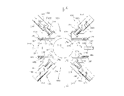
Figure 1 represents a diagrammatic cross-section view of a machine for
molding, filling and automatic; closing of wrappings in accordance with this
invention, in the area of the unpleating system, and
Figure 2 represents an axial cross-section of the same machine according to
the sectional plane indicated with reference II-II on figure 1.
This invention applies in particular to the production of wrappings based on
films of thermoplastic material. Nonetheless, the invention may find
application in
the molding of bags based on film of a different nature, for example aluminum
or
paper-based.
Z j ~OOg
-4-
The general structure of the machines for molding, filling and
automatic closing of flexible-film-based wrappings, well known to the person
skilled
in the art, will not be described in detail below.
On the attached figures, the longitudinal axis of these machines, which
coincides with the direction of travel of the film intended to constitute the
wrapping,
is indicated with reference O-O.
This longitudinal axis O-O is generally vertical. Nonetheless, as a
variation, for certain machines the O-O axis may be horizontal.
On the attached figures 1 and 2, the conventional filling spout which
opens into the tube formed by the film shaped on the molding collar has been
represented with reference 10.
In addition, on the attached figures 1 and 2, the transverse welding
plane of the film has been indicated with reference S.
As has been indicated previously, the unpleating system in accordance
with this invention comprises two units 100 capable of sequenced travel toward
and
away from the transverse welding plane S. These units 100 are preferably
symmetrical with respect to one another in relation to the transverse welding
plane
S. This plane S will be designated below as principal plane of symmetry.
Additionally, the units 100 preferably have a second symmetry in relation to
the
sectional plane II-II of figure 2, orthogonal to the transverse welding plane
S and
passing through the longitudinal axis O-O. This plane will be designated below
as the
secondary plane of symmetry.
The units 100 are moved by any appropriate conventional means,
preferably hydraulically-controlled jacks. These are not represented on the
attached
figures, in order to simplify the illustration.
~ l 9,Qp~~
-5-
The units 100 are moved toward the transverse welding plane S, prior
to the effecting of a transverse weld, to pull the film in its width and to
eliminate any
pleat which may be present. The units 100 then are moved away from the
transverse
welding plane S, after effecting of the transverse weld, so as to allow the
forward
movement of the film according to the O-O axis.
The units 100 preferably are placed in a fixed position in relation to
the forward-movement axis O-O. Nonetheless, as a variant, means may be
provided
ensuring travel of the units 100 parallel to the axis O-O, there again back
and forth,
to accompany the film, in its forward movement, and to limit dead time due to
the
travel time of the units 100 toward and away from the transverse welding plane
S.
According to the preferred mode of embodiment represented on the
attached figures, each unit 100 holds two flexible jacks 150.
Each of these flexible jacks 150 can be formed, for example, of a main
portion 152 and a rod 154 movable in translation with respect to the main
portion 152
and stretched out by a built-in spring not visible on the attached figures.
According to the specific and non-restrictive mode of embodiment
represented on the attached figures, the axes 156 of the four flexible jacks
150 are
slanted on the order of 45 ° in relation to the transverse welding
plane S (principal
plane of symmetry) and in relation to the secondary plane of symmetry which
coincides with the direction of travel of the units 100. Thus, the axes 156 of
the four
flexible jacks 150 are secants with respect to the longitudinal axis O-O.
It is understood that this arrangement makes it possible to free up a
considerable central space between the two flexible jacks 150 with which each
unit
100 is equipped.
Means allowing an adjustment of positioning of each flexible jack 150
on the associated unit 100 preferably is provided. These means of adjustment
may
CA 02190084 2000-03-31
-6-
assume numerous shapes. They are diagrammed under reference 160 on the
attached
figure 1.
These means of adjustment 160 may be made up of slots parallel to the
secondary plane of symunetry II-II, and accepting complementary blocking
means.
Such means 160 make it possible to adjust the position of the jacks 150 on the
associated unit 100, in relation to the principal plane of symmetry S, that
is, parallel
to the secondary plane of symmetry II-II.
The rod 154 of each flexible jack is equipped with a pulling mechanism
170.
In the case in question, the pulling mechanisms 170 are made up
essentially of a small bar 172 oriented parallel to the transverse welding
plane S-S.
Preferably means are provided making it possible to adjust the position
of the pulling mechanisms 17 n with respect to the rods 154, in a plane
parallel
to the transverse welding plane ;S-S. There again, these means of adjustment
may be
subject to numerous modes of embodiment.
As illustrated in the attached figure 1 under reference 174, these means
of adjustment of the pulling mechanisms may be made up of an oblong aperture
formed in the small bar;. 172, parallel to the transverse welding plane S-v
and adapted
to accept complementary blocking mechanisms on the associated piston rod 154.
Still more precisely, according to this invention, the pulling
mechanisms 170 placed near the: edge of the film intended to constitute the
bottom of
a bag (represented on the left side of figure 1) preferably are equipped with
flanges
176 directed toward dire transverse welding plane S, allowing a relative
sliding
between said flange and the film making up the bag.
On the other hand, the pulling mechanisms 170 positioned facing the
z ~ 9ops4
_7_
edge of the film intended to constitute the opening of a bag, and consequently
generally equipped with closing profiles in relief (represented on the right
side of
figure 1) are preferably provided with projecting pulling fingers 178 directed
toward
the transverse welding plane S.
Each of the units 100 preferably is adapted to serve as a support for
the transverse welding jaws and/or cutting blades making it possible to
separate a
finished bag from the film downstream.
According to the invention, means designed to guarantee a positioning
of each unit 100 strictly parallel to the transverse welding plane S, that is,
a
translation travel of each unit 100 in a direction strictly orthogonal to this
transverse
welding plane S, are provided.
These securing means may be subjected to numerous modes of
embodiment.
According to a first mode of embodiment, these securing means may
be made up of complementary structures provided on the two units 100
respectively,
for example a finger or a rod integral with one of the units 100, oriented
perpendicularly to the transverse welding plane S and inserted into a
complementary
boring made in the other unit 100.
According to another embodiment variant represented in the attached
figures, the cited securing means comprise stops 200 integral with the frame
of the
machine, symmetrical in relation to the transverse welding plane S and
preferably
having lateral facets 202 parallel to this plane.
In this case, a roller means, on each pulling mechanism 170, preferably
is provided to facilitate travel of each pulling mechanism on the associated
stop 200
and parallel to the transverse welding plane S.
~~9~0~4
_g_
Thus, as represented on the attached figure 1, each pulling mechanism
170 preferably is provided with a slide 180 equipped with a roller 182. The
roller 182
projects in relation to the slide 180 in the direction of the transverse
welding plane
S to rest on a stop 200 when the unit 100 is moved toward this welding plane
S. The
slide 180 which bears the roller 182 is capable of flexible clearance in
relation to the
associated small bar 172 in a direction orthogonal to the transverse welding
plane S.
The slide 180, however, is brought back to a resting position in relation to
the small
bar 172, by a flexible mechanism not represented on the attached figures in
order to
simplify the illustration.
In practice, an unpleating unit of the type illustrated in the attached
figures may be provided above and/or below the transverse welding jaws.
The functioning of the unpleating device according to this invention is
essentially the following.
Prior to the effecting of a transverse weld, the two units 100 are moved
toward the transverse welding plane S. The positioning of the units 100
parallel to the
transverse welding plane S is defined by the support of the rollers 182 on the
stops
200.
The flanges 176 contact the edge of the film corresponding to the
bottom of the bags. The fingers 178 contact the opposite edge of the film
corresponding to the mouth equipped with closing profiles. After support of
the
rollers 182 on the stops 200, the rods 154 are retracted into the frame 152.
This
results in travel of the pulling mechanisms 170, and consequently of the
flanges 176
and forgers 178 radially toward the outside of the longitudinal axis O-O. It
is
understood that the two diametrically opposite edges of the tubular film
corresponding
to the bottom and the mouth of the bags respectively, thereby are pulled out
with
relative travel allowed between the film and the flanges 176. This arrangement
makes
it possible to eliminate any potential pleat in the film.
219Q08~
-9-
Once the transverse welding has been effected, the units 100 can be
- drawn aside.
The pistons 154 and associated pulling mechanisms 170 then
automatically resume their resting position in preparation for a new cycle of
travel
and pulling.
This invention offers numerous advantages with respect to the
previously-known unpleating systems.
First of all, it will be noted that most of the known unpleating devices
take up the entire width of the machines for molding, filling and automatic
closing
of bags and thus generally require a bag height in excess of the useful height
in an
amount corresponding to obstruction of the tracking systems.
On the contrary, this invention makes it possible to completely free up
the central portion of the tubular film and consequently allows the production
of bags
limited strictly to the useful height for packaging of the product concerned.
Furthermore, this invention makes it possible to be completely of any
tong-action system, in particular specifically based on hydraulic jacks. Thus,
this
invention allows more rapid manufacturing sequences than the previously-known
machines.
This invention, of course, is not limited to the specific mode of
embodiment which has just been described, but extends to any variant in
conformity
with its nature.