Note: Descriptions are shown in the official language in which they were submitted.
' 2190193
1
SEALING UNIT WITH AXIAL BRUSHES
CONTROLLED BY STATIC PRESSURE IN AXIAL MOVEMENT
DESCRIPTION
This invention relates to a sealing unit placed
between a stator and a self-rotating rotor plate which
is surrounded by the stator_
One conventional sealing means used in
aeroplane engines consists of placing a labyrinth seal
across the clearance between the stator and rotor ; it
is a device consisting of parallel, flat ridges
called blades - positioned on the rotor and projecting
towards the stator which rub against a layer ofsoft
material - so-called abradable - which covers the
stator and which they erode in such manner that there
remains only very little clearance with this layer_ _
Particular states of the motor may, however,
produce exceptional differential thermal expansion
which causes the blades to penetrate deeper into the
abradable so that under subsequent normal conditions of
use the clearance will much greater; the conclusion
must therefore be drawn that the advantage of this type
of joint is compromised.
Other currently used joints for this function
are elastic joints which comprise either elements such
as brush pins fixed to one of the components of the
assembly which rub against the other component, which
bends them, or elements moulded into rigid lips mounted
by means of springs onto one of the components and
pushed back against the other component by these
springs.
These joints are satisfactory for numerous
applications, but differential expansion in radial
SP 10853 JCI
2~90Tg3
.~
2
direction between the rotors and stators under
consideration is too great for these joints to be used
under good conditions as--the clearance to be filled
varies to such extremes that in practice the clearance
is either too excessive or on the contrary too small
for the chosen joint which therefore losses its
efficacy or -wears prematurely according to the
situation.
The invention is based on a new idea which
nevertheless uses elastic-joints to make a seal between
the stator and rotor ; but instead of placing them in
the form of radially oriented flat sealihg joints in
accordance with known concepts so that they rub against
the edge of the rotor plate, axially oriented
cylindrical joints are used which rub against the
peripheries of flat surfaces opposite the rotor -This
arrangement is not sufficient in itself as differential
thermal expansion also exerts itself in axial
direction, so that the same problems arise of wide
variations in clearance.
It is therefore in accordance with the
invention to have these elastic joints carried by a
stator floating body, which is axially mobile in
relation to the stator, which surrounds the rotor, and
whose function is to follow the axial movements of the
rotor to ensure good operating conditions for the
elastic joints at all times.
A slightly more complicated arrangement is
subsequently necessary and the invention therefore
consists of a sealing unit placed between a stator and
a rotor plate rotating around an axis, separating a
high pressure sector from a low pressure sector,-
comprising a body that is fixed during --rotation and
mobile during translation in the stator depending upon
the axis, characterized in that the body comprises two
SP 10853 JCI
23 9~I 93
3
sides covering the peripheries of two -surfaces of the
plate which are opposite and each directed towards one-
of the sectors, and in that it comprises -_ two elastic
sealing joints of cylindrical shape and with axial
extension each compressed between one of the sides and
one of the opposite surfaces ; two stop gaskets of
cylindrical shape and with axial extension each lying-
between one of the sides and one of the opposite
surfaces but which are shorter than the elastic -
joints ; one of the stop gaskets surrounding one of the
elastic joints towards the high pressure sector, and _
one of the elastic joints surrounding one of the stop
gaskets towards the low pressure sector ; and two
alternate expansion sealing joints of flat, circular ,
shape placed between the stator and end parts of the
sealing body each in one of the sectors, each with an
outer diameter equivalent to the diameter of the
elastic joint positioned towards the same sector.
An axially floating body whose purpose is -to -
contribute towards making a seal between two sectors of
different pressure in a gas turbine is illustrated in
French patent 2 018 924, but its structure is
different : a sliding body (60) ends in two circular,
concentric lips (74 and 76) which rest against a flat
component (34) with which they have clearance. The
chamber (80) bounded by the lips (74 and 76) and the
flat component (84) receives a gas supply through an
opening (82). When the supply flow rate varies, the
pressure in the chamber also varies and the body (60)
slides under the effect ofthe resulting pressure force
to which it is subjected ; it subsequently modifies the
width of clearance and therefore the opening of the
chamber (80) through which the gases can escape; which
restores the required pressure within the chamber. -
SP 10853 JCI
CA 02190193 2004-09-29
4
The invention shall be described in more detail
below using the figures appended as a guide which
illustrate a non-restrictive embodiment of the
invention .
figure 1 represents the invention at rest, and
figure 2 represents the invention when this
state of balance is disturbed.
The invention can therefore be used in a gas
turbine between a stator 1 and a rotor which are only
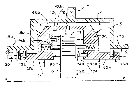
partially represented. Stator 1 is essentially made up
of a wall 2 which, between two cylindrical surfaces 3a
and 3b having the same diameter, has a recess 4
corresponding to a cylindrical portion of wider
diameter. A peripheral chamber 5 is formed in recess 4.
The essential component of the rotor here is a plate 6
rotating around an axis X-X concentric to parts 3a, 3b
and 4 of stator 1 and which extends partly into
peripheral chamber 5, its diameter being greater than
that of the cylindrical surfaces 3a and 3b.
The part characterizing the invention is a
stator floating body 7, in the shape of a collar
surrounding the periphery of rotor plate 6. More
precisely, its section is in the form of a cap divided
into . two symmetrical sides 8a and 8b, each covering
one end of one of the flat, lateral, opposite surfaces
9a and 9b of rotor plate 6 ; a cylindrical intermediate
section 10 which connects them together at their ends
with the widest diameter, surrounding edge 11 of rotor
plate 6 and extending exclusively into peripheral
chamber 5 ; and two rim parts 12a and 12b starting from
the opposite end of sides 8a and 8b, of smaller
diameter, which diverge to enter into cylindrical
surfaces 3a and 3b being concentric with the latter.
Rims 12a and 12b carry expansion joints 13a and
13b which rub precisely against cylindrical surfaces 3a
2190193
and 3b in accordance with the sliding movements of
floating body 7 along axis X ; they provide support for
floating body 7 by-resting against cylindrical surfaces
3a and 3b and they contribute towards separating the
S volume of peripheral chambers from the free parts a
and b of the machine situated either side of rotor
plate 6 of which the first is a low pressure area and
the second a high pressure area.
Two elastic joints 14a and 14b are also used
which may be brush joints made up of flexible pins or,
as shown here, joints made up of a rigid sealing lip
pushed back by a spring against the component, here
rotor plate 6, against which they rub. Elastic joints
14a and 14b are fixed to floating body 7, for example
by being inserted into grooves 15a and 15b of the
latter, in which the springs are fully recessed.-They
are cylindrical in shape and oriented axially ; they
each have the same diameter which is more or-less
similar to the outer-diameter of expansion joints 13a
and 13b, or to the diameter of cylindrical surfaces 3a
and 3b.
Finally two stop gaskets 16a and 16b can be-
seen, fixed in the same way as the two previous joints
to the opposing surfaces of sides 8a and 8b and
oxiented towards rotor plate 6 ; they too are of
cylindrical shape and have axial direction, but
contrary to the previous joints, they do not extend as
far as side surfaces 9a and 9b of rotor plate 6 but
remain separated from these surfaces by a clearance 17a
or 17b in the state of balance shown in figure 1.
Another feature of these gaskets 16a and 16b is that
they are not symmetrical ; 16a situated on the low
pressure side « a r is surrounded by the corresponding
elastic joint 14a, whereas the other- stop gasket 16b
SP 10853 JCI
6
has a wider diameter than the other elastic joint 14b
and is located in peripheral chamber 5_
A locking pin 19 fixed to one of cylindrical
surfaces 3b in between the two branches of a fork 20
extending beyond one of rims 12b prevents floating body
7 from rotating.
Peripheral chamber 5. considered for the
functioning of the invention has its volume bounded by
recess 4, the periphery of stator plate 6, rims 12a and
12b and expansion and elastic joints 13a and 13b, 14a
and 14b. Its unity is maintained by a hole 18 made
through the intermediate part 10 of floating body 7.
The pressure in this chamber, exerting itself on its
surfaces, is shown by arrows, and the pressures in
areas a and b subject to high pressure and low pressure
are shown by different types of arrows. The specialist
will note almost immediately that the forces exerted by
these different pressures on the free surfaces of
floating body 7 all cancel each other out in axial
direction, mainly due to the choice of diameters of
elastic joints 14a and 14b. As these elastic joints 14a
and 14b are compressed in the same way by rotor plate
6, the balance is undisturbed and floating body 7
remains immobile ; leaks may be observed through
- elastic joints 14a and 14b but they offset each -other
and the pressure remains unchanged in peripheral
chamber 5.
If the position of rotor plate 6 is disturbed
in axial direction, the situation shown in figure 2 may
arise _ rotor plate 6 has moved towards high pressure
area b, has pushed back the corresponding elastic joint
14b and has finally come to stop against gasket 16b ;
in this situation the other elastic joint 14a is
detached from stator plate 6 or at Least pushes much
less strongly against it so that the same quality seal
SP 10853 JCI
' ~~'~~~J~
is no longer ensured. The consequence is -that
peripheral chamber 5 which was previously subjected to
an intermediate pressure between low pressure andhigh
pressure, opens under the effect of the low pressure
and its pressure eventually becomes absolutely equal to
this low pressure. A situation is reached whereby the
seal is chiefly ensured by expansion joint I3b and stop
gasket 16b on the high pressure side, and elastic joint
14b on the high pressure side has a reduced sealing
effect so that it can be considered that. the space
between it and stop gasket 16b also becomes a high
pressure site.
In this situation in which the pressure of
peripheral chamber 5 is reduced, an imbalance is
perceived due to the irruption of high pressure between
joints 14b and 16b : floating body 7 is subsequently
subjected to a resulting pressure force directed
towards the high pressures which moves the body to the
left just as rotor plate 6 previously. This movement of
floating body 7 lasts until elastic joints 14a and 14b
again exert the same sealing effect and the situation
of balance in figure 1 is restored, rotor plate 6 and
floating body 7 nevertheless having made an identical
movement.
A symmetrical situation appears when rotor
plate 2 moves towards the low pressure area : in this
case it is the stop gasket 16a on the low pressure side
which exerts the main sealing effect, and the high
pressures will exert on floating body 7 a resultant
force directed towards the right exerting itself
between elastic joint 14a and stop gasket 16a on the-
low pressure side : floating body 7 will then be pushed
back towards the right again tending towards the
position of balance.
SP 10853 JCI _
' 2190193
The surfaces of rotor plate 6 on which elastic
joints 14 and stop gaskets 16 rub are polished to form
friction mirrors-.
Elastic- joints 14 may of known kinds, in
particular made up of brush pins.
SP 10853 JCI