Note: Descriptions are shown in the official language in which they were submitted.
2190204
1
COUNTERS FOR FhUID DISPENSERS
BACKGROUND OF THE INVENTION
Field of the Invention
The invention relates to devices for indicating
the number of fluid dispensations remaining in a
container from which metered dispensations are made.
Brief Description of Related Art
A wide variety of fluid dispensers are known and
commercially available to dispense metered
proportions of a contained fluid from containers.
For example, U.S. Patent 3,749,290 describes a
trigger actuated dispensing pump assembled with a
fluid container. Upon actuation, a measured
proportion of the contained fluid is dispensed from
the containers.
Of particular importance as fluid dispensers are
metered dose inhalers (MDI) employed to administer
fluid medications to animals, including humans.
The use of inhalers is well known and the art
has developed over the past twenty five years to
cover many versions of the basic concept of a
"pumping" type medication applicator. The device may
be manually pumped (such as described in U.S. Patent
5,284,132) or a pumping like cycle may be utilized.
The medication may also be repeatedly released from
a pressurized disposable canister to create repeated
sprays or inhalations as needed.
Representative of the early inhalers for oral
and intra-nasal administration of medications are
those described in, for example, U.S. Patents
3,361,306; 3,183,907; 3,565,070: 4 206 758;
4,803,978; 4,934,358; 4,955,371; 5,060,643;' and
5,351,683. Representative of nasal-pharyngeal
2
inhalers for large mammals such as a horse is that
described in U.S. 5,062,423.
Metered dose inhalers (MDIs) are, at present,
the most efficient and best-accepted means for
accurately delivering medications in small doses to
an animal's respiratory tract. Therapeutic agents
commonly delivered by the inhalation route include
bronchodilators (B2 agonists and anticholinergics),
corticosteroids, and anti-allergics. Inhalation
may also be a viable route for anti-infective,
vaccinating, systemically acting and diagnostic
agents, as well as anti-leukotrienes, anti-proteases
and the like.
MDIs are available in several types. Most
frequently, MDIs comprise a pressure resistant
container (canister) typically filled under super
.atmospheric pressures with a product such as a drug
dissolved in a liquified propellant, or micronized
particles suspended in a liquified propellant. The
container is fitted with a metering valve. The valve
is movable from an inner (charging) position to an
outer (discharging) position. A spring bias holds
the valve in the charged position until forced to the
discharge position. Actuation of the metering valve
allows a metered portion of the canister content to
be released, whereby the pressure of the liquified
propellant carries the dissolved or micronized drug
particles out of the container and to the patient.
A valve actuator also functions to direct the aerosol
as a spray into the patient's oropharynx.
Surfactants are usually dissolved in the aerosol
formulation and can serve the dual functions of
lubricating the valve and reducing aggregation of
micronized particles.
CA 02190204 2004-O1-07
3
Representative of pharmaceutical formulations
for use~in metered dose inhalers are those described
in U.S. Patent 5,190,029. The MDI devices for
administering such pharmaceutical formulations are
also well known as seen for example in the
descriptions given in U.S. Patents 3,361,306:
3,565,070 and 4,955,371.
A disadvantage arising from use of the known
devices is that the patient cannot determine the
amount of medicament in the aerosol container at any
given time. The containers are generally not
transparent to view, being light protective of the
contents. Shaking them will not always reveal
auditory information as to their contents. In an
extreme case this could mean that the patient,
possibly suffering from severe bronchospasm or like
emergency condition and needing a dose of medicament,
will find that the aerosol container will not
dispense a dose, because its contents have been
previously exhausted. The problem has been
recognized and consideration given to solutions. For
example, U.S. Patent No. 4,817,822 describes an
inhaler device which includes a counting means for
indicating the relative emptiness of a container or
the number of doses dispensed. However, this inhaler
counting mechanism is physically attached to the
aerosol container as well as the inhaler, such as by
a retaining ring or retaining cap. In one
embodiment, the counting means is a separate sleeve
fitting on the up-turned bottom of the aerosol
container. It is easy to lose, not being integrated
with the inhaler, but an ancillary unit slipped over
the loose aerosol container. In another embodiment,
the counting means requires a secured attachment to
21902U~
4
the aerosol container neck, which prevents removal of
the container from the inhaler, even when empty. The
inhaler device is only useful for use with the
original aerosol container and can not be used with
aerosol refill containers.
The U.S. Patent 5,020,527 presents an
improvement over the dose counting means of U.S.
Patent 4,817,822 wherein the mechanical counter can
be replaced with an electronic counter. The improved
inhaler can indicate the number of doses remaining in
the aerosol container. However, the device is not
fool-proof in operation, which can be a disadvantage
in the hands of a severely debilitated, confused or
forgetful patient. In households which include small
children they have been known to "play" with the
MDI's when unsupervised access is possible. Infants
can accidentally reset or interfere with established
counts in the mechanical devices. For example, the
counter can be accidentally reset, obviating its
usefulness and, in fact, misleading of the patient as
to the true number of doses remaining in the
container. Also, the counter can not be
automatically reset when a full, new aerosol
container (refill) is to be used. This can affect
the accuracy of the count carried out.
In addition, the inhaler of the U.S. Patent
5,020,527 still employs a mechanical trigger to
actuate the counting means. It is subject to
triggering of the counter without actual
administration of a dose from the container, for
example, when the aerosol container is removed and
the inhaler device washed and disinfected,
independent of the aerosol container.
These, and other problems associated with the
inhalers and other fluid dispensers of the prior art
21~~204
are solved by the present invention, described
hereinafter. The device of the invention is
economical to manufacture, assemble with fluid
containers and disposable when the container is
5 empty, in the same manner currently followed in
disposing of the containers.
The device of the invention is intended for use
with one fluid container and is disposable with it
when the contents are emptied. One need not reset a
counter with the errors attendant with such a
procedure.
BUMMARY OF THE INVENTION
The invention comprises a device for indicating
the number of dispensations remaining in a container
for holding and dispensing metered quantities of a
fluid, which comprises;
a. a tubular housing, having
i. a first end;
ii. a second end;
iii. a tubular body joining the first and
second ends;
said tubular body together with the
first and second ends defining a
hollow chamber;
b. a flexible first closure, closing the first
end;
c. a second closure closing the second end:
d. microelectronic means mounted in the
chamber, for receiving a signal upon
dispensation of a fluid from the container,
calculating the number of dispensations
remaining in the container and indicating
the calculation upon determination of a
pre-determined number of remaining
dispensations;
~i~~~~~
6
e. means for signalling to the microelectronic
means upon the occurrence of each
dispensation, positioned proximal to the
first end of the tubular housing: and
f. means on the second end of the tubular
housing for mounting the device on a fluid
container assembly in a position where
dispensation of a metered dose,
simultaneously activates the means for
signalling.
The device of the invention is useful to
maintain a running inventory of a predetermined
quantity of fluid to be dispensed from a container
and to signal when a predetermined number of
dispensations remains in the container. It is
relatively simple to operate, even by young children
(6 to 12 years of age). For example, the
invention enables one to maintain a count of
medication dispensations remaining for use in metered
dose inhalers and other fluid dispensers.
BRIEF DESCRIPTION OF THE DRAWINGS
Embodiments of the present invention will be
described with reference to the accompanying drawings
in which:
Figure 1 is a perspective view of an embodiment
metered dose inhaler of the invention shown in
assembly with a metered dose inhaler aerosol
canister.
Figure 2 is a cross-sectional side view of the
assembly shown in Figure 1.
Figure 3 is an enlarged cross-sectional side
view of the count-down component shown in the
assembly of Figures 1 and 2.
CA 02190204 2004-O1-07
7
Figure 4 is an illustration of an embodiment
microelectronic circuit component of the micro-
electronic indicator means shown in Figure 3.
Figure 5 is a longitudinal sectional view of a
pump associated with the neck of a fluid container,
as taken from Figure 9 of U.S. Patent 3,749,290,
and modified to include assembly with the device of
the invention shown in Figures 1-4.
DETAI?~ED DESCRIPTION OF T8E PREFERRED
EMBODIMENTB OF T8E INVENTION
Those skilled in the art will gain an
understanding of the invention from a reading of the
following description of the preferred embodiments
when read in conjunction with. a viewing of the
accompanying drawings of Figures 1-5, inclusive.
Figure 1 is a view-in-perspective of an
embodiment assembly 10 of the invention, which
comprises an open ended, hollow tube l2 assembled
with an aerosol canister 16 upon which' there is
mounted a device 30 of the invention. The assembly
10 is a metered dose inhaler, as is known and
conventional in the prior art, but improved by the
inclusion of the device 30, which contains a
microelectronic means for dispensations from the
canister l6, calculating the number of dispensations
remaining in the canister 16 and further, indicating
the calculation upon determining that a pre
determined number of dispensations remain in the
canister 16.
Figure 2 is a cross-sectional side elevation of
the assembly 10 shown in Figure 1, and depicts
further structural details of'the embodiment assembly
of the invention. As shown in Figure 2, there is
seen a cross-sectional side elevation of an embodi-
2190204
8
went metered dose inhaler 10 of the invention. The
inhaler 10 is essentially a hollow tube 12 having a
first open end 14, which by size and configuration is
adapted to receive in assembly an aerosol canister
16. A small vent aperture 13 may be advantageous to
vent the tube 12 during use, allowing ambient air in.
The aerosol canister 16 is fitted with a conventional
metering valve (not seen in Figure 2) and spray stem
18. Such canisters 16 are commercially available
from the Bespak Co., North Carolina, U.S.A. They may
contain any of the pharmaceutical preparations
conventionally used in oral and nasal medicators,
such as described for example in the U.S. Patent
5,190,029. The assembled tube 12 and canister 16
locates the canister 16 partially within tube 12
hollow 20. Open end 22 communicates with hollow 20
.and is adapted by size and configuration to form a
mouthpiece for insertion in the oral cavity of a
patient and to couple or sealingly engage with the
oral lips for inspiration and expiration of the
breath of a mammal. Alternatively, end 22 can be
adapted to engage with the patient's nasal passages.
Within the hollow 20 is fixedly mounted a spray-
directing element 23 which includes a continuous
internal conduit 24. The conduit 24 couples with the
stem 18 of the aerosol canister 16 and directs a
metered dose therefrom out of nozzle 26 as a spray
toward the open end 22 of the tube 12 when the
canister 16 is pushed downwardly by the user. The
valve of canister 16 is activated to release a
metered dose. The valve is activated when the
patient pushes the canister 16 downward, forcing the
stem 18 against the element 23, opening the valve
mentioned above. In a preferred embodiment of the
invention, the interior walls of tube 12 at end 14
CA 02190204 2004-O1-07
9
and inward may be closely fitted to the walls of
canister 16 (a sliding engagement) so the canister 16
will move freely within hollow 20 until stem 18 is
stopped by element.23, but is sufficiently close
fitting, to avoid escape of aerosol spray through open
end 14 during use. As shown in both Figure 1 and
Figure 2, the up-turned canister 16 slidingly engaged
in the hollow 20 through end 14 is accessible to be
pushed down on element 23. When depressed upon
element 23, the valve on the canister 16 opens to
release a metered dose of the aerosol formulation,
through stem 18 and conduit 24 to spray from nozzle
26 towards the open end 22 of the tube 12. One dose
is released from aerosol canister 16 each time it is
fully depressed upon element 23. Release of pressure
on canister 16 returns it to the non-depressed
position, charging its valve for a further discharge
of a dose when the valve is again activated. As
shown in Figure 2 the valve is concealed within the
neck of canister 16, and functions when the stem 18
is pushed interiorly of canister 16: the valve itself
is not shown in the Figures 1-2 being conventional
and within the enclosure of the canister 16 itself.
A$ described to this point inhaler assembly 10 is a
known device, and can be for example as detailed in
the U.S. Patent 3,361,306.
The known inhaler is modified as
described hereinafter to manufacture the inhaler
assembly 10 of the invention. Integral to canister
16, preferably adhesively attached and non-removable
from the exterior of canister 16 in a location on the
upturned bottom of canister 16 is a hermetically
sealed device 30 for the containment of micro-
electronic means for determining the number of doses
remaining in the canister 16 after each activation
~I9U20~
and release of a metered dose. The positioning of
device 30 on the upturned bottom of canister 16
enables the operator to depress the canister 16 as
described above by pressing on the sheet 60 of device
5 30 with a finger. The containment of the
microelectronic counter means within a hermetically
sealed device 30 permits the user to remove the
canister 16 at any time, with attached device 30 to
wash the tube 12 (inside and out) with water, soaps,
10 disinfectants and antiseptic solutions with no damage
to or interference with an ongoing count, as will be
described more fully hereinafter. This is important,
because sprays of many aerosol formulations leave
tacky residues which will entrap dust and dirt
particles. Some provide a media for the growth of
undesired microorganisms. If the growth of these
microorganisms is unchecked, they can serve as a
source of infection for the patient, and will often
introduce pathogens into the patent's respiratory
tract. Referring now to Figure 3, there is seen an
enlarged view in cross-section of an embodiment
device 30 containing microelectronic means for
maintaining an inventory of the doses remaining in
canister 16. The Figure 3 does not show the
electrical wiring between component parts, for
clarity of the drawing. Hermetically sealed within
an interior chamber 40 of the device 30 is a power
source 32, for example, a long-life battery such as
the conventional and known nickel-cadmium or lithium
batteries providing circa 1 to 3.0 volts of electric
power. Mounted on a printed circuit board 34 and
powered by the power source 32 is an application
specific integrated circuit (ASIC) 36 such as a logic
array or a microprocessor programmed to process
electrical signals from a sensor and trigger a
11
signalling device 38 such as, for example, a tactile
alerting device, an audible alarm, a visual
indicator, for example, a light emitting diode (LED)
or a liquid crystal display (LCD) to give an alpha-
s numeric readout. LCD devices controlled by
electronic signals from ASIC 36 are well known and
may be for example the type described in U.S. Patents
4,804,953; 5,227,899; and 5,227,901. The ASIC 36 is
a control means. The ASIC 36 can be a digital
integrated circuit serving at least some of the
control functions hereinafter enumerated, including
timing functions, calculations of the number of dose
actuations, memory recordings, visual and auditory
indicators. Actuating the ASIC 36 is a switch 42,
within chamber 40 of device 30, adjacent to the
flexible sheet 60.
Device 30 is a tubular housing 50 having a first
end 52, a second end 54 and a tubular body 56 joining
the first and second ends 52 , 54 : The ends 52 , 54
together with body 56 defines an interior, hollow
chamber 40. The end 52 of the tubular housing 50 is
closed with a flexible sheet 60. The end 54 is
closed with a sheet or wall 62. A flange 64
circumscribes the periphery 66 of the second end and
serves as a means for frictional engagement with
canister 16 bottom to attach the device 30.
Advantageously, the device 30 is adhesively secured
in place on canister 16.
The device 30 housing 50 is preferably made of
a transparent or translucent polymeric resin
material, and shaped like an inverted cup. The
preferred synthetic polymeric resin material for
fabricating the device 30 is light transmitting so
that when exposed to an interior relatively low level
light sources, it appears luminous and illuminates
2190201
12
adjacent areas. The resin body of the device 30 may
be coated on interior surfaces thereof to selectively
reflect inwardly or diffuse light, as desired.
Representative of the synthetic polymeric resins
useful to mold housing 50 of device 30 are
thermoplastic polyolefins, polyurethanes,
polycarbonates and poly(methlmethacrylate),
particularly those which are semi-rigid and having
some flexibility to facilitate installations and
operation as described hereinafter. The interior
walls of housing 50 of device 30, defining the
chamber 40 may bear a plurality of grooves 68
cooperating to form a Fresnel lens, for magnification
of a light display within chamber 40.
The Fresnel lens functions as a light projection
device, to enhance light emanating from sources of
low level light having varied colors, affording a
polychromatic display of the light through the walls
of the housing 50 including end 52 sheet 60.
As shown in Figure 3, the PC board 34 is used to
mount one or more light sources such as for example
light emitting diodes (LEDs) 48 red or green in
color. Preferably when a plurality of light sources
are used, these LEDs 48 are disposed substantially
equi-distantly around the perimeter of board 34.
Figure 4 is a schematic plan showing embodiment
circuitry means for the microprocessor means
described above.
The ASIC 36 may be programmed by the
manufacturer, to sense and countdown the predeter
mined number of doses remaining in canister 16 after
each use of the assembled apparatus. It can, for
example, be programmed to operate as follows:
When a full canister 16 is put into the inhaler
assembly 10, with the attached and secured device 30,
.,...- X19 ~ ~ ~4
13
depressed to cause an initial delivery of a metered
dose of medication from the canister 16 as previously
described, the ASIC means will start the count
process. During normal usage, the canister 16 may be
removed at any time for washing the inhaler 10 and
then replaced without altering the ongoing count.
The dose counter microelectronic means audibly or
visually signals after 180 of 200 doses (or any set
number) have been dispensed. A red LED 48 may be
programmed to flash twice a second for 10 seconds on
each use after 180 doses have been administered and
this illumination will be seen through the light-
transparent sheet 60 or housing 50 of the device 30.
After a further 10 doses, for example, are dispensed,
for instance at dose 191, an audible tone may sound
a number of times after each inhaler 10 use
indicating the count of remaining doses, upon
reaching the final dose, there can be a long
sustained audible tone or constant illumination of
LED 48 of perhaps 10 seconds duration.
The Application Specific Integrated Circuit
(ASIC) 36 is set at manufacture for a total count of
for example, 200 doses. Each time the patient
depresses the medication canister 16 for an inhaled
dose of, for example, Albuterol~, switch 42 is closed
by downward digit pressure on sheet 60 of device 30,
simultaneously with the downward motion of the
canister 16. The switch 42 closure triggers the
microelectronic means to subtract "one" from any
count. Successive uses to the, for example, 180th
dose are carried out in the same way. Starting with
the 181st dose delivery, the LED 48 may flash several
times after depressing the canister (perhaps 20
flashes in 10 seconds). This visual signal indicates
it is time to seek a refill of the prescribed
2190204
14
medication. The signal with each successive dose
repeats to the final dose remaining, (200th), at
which time the LED 48 may be programmed to stay on
until the battery exhausts or the canister 16 with
attached device 30 is replaced. The device 30 is
disposable and can be disposed of with the empty
canister 16.
By construction of the device 30, and
flexibility of sheet 60 to activate switch 42,
thereby triggering a countdown, one can ensure that
false counts will not occur while carrying the
assembly 10. The micro-switch 42 can be selected to
operate, for example, at 3 to 7 lbs. of pressure.
The typical pressure required to press canister 16
downward in the prior art assembly of an MDI is about
3 lbs.
As a further alternative, in conjunction with a
liquid crystal display (LCD), the ASIC 36 can be
programmed to provide a (LCD) giving total number of
doses remaining.
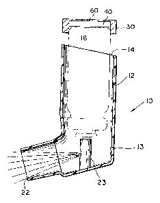
Figure 5 is a cross-sectional side elevation of
a trigger actuated dispensing pump l0a mounted on a
container 16a (shown fragmented). The container 16a
may be non-transparent so that one can not visually
determine the contents thereof. Adhesively secured
to the trigger 17a for actuating the pump l0a is a
device 30a, identical in all respects to the device
described above. When the trigger 17a is pulled
by the operator's finger, a digit placed on sheet 60a
30 of the housing 50a as described above actuates
through the switch 42 the ASIC 36 means previously
described. As mentioned above, the device 30a can be
constructed with a microswitch 42a which will
function at any selected pressure, generally within
15
the range of about 3 to 10 lbs., to avoid false
counts during operation of the trigger 17a.