Note: Descriptions are shown in the official language in which they were submitted.
2190316 -
IMPROVED DEHUMIDIFIER
FIELD OF THE INVENTION
This invention is directed toward a new dehumidifier
and a method for operating the dehumidifier.
The invention is more particularly directed toward a
dehumidifier with novel means for use in defrosting the
dehumidifier and a novel method for defrosting the
dehumidifier.
BACKGROUND ART
Known dehumidifiers have a conditioning area in an
air duct. An air mover, such as a fan, in the air duct draws
air from a room through the conditioning area to dehumidify it.
The conditioning area has an evaporator for cooling a portion
of the air passing through the duct to cause moisture to
condense from the air onto the evaporator to control its
humidity. The moisture is collected from the evaporator in a
drain pan located under the evaporator. The conditioning area
also has a condenser for heating the reminder of the air
passing through the duct. This heated air portion is mixed with
the dehumidified air portion so that the air returned to the
room is at a slightly higher temperature than the temperature
at which it left the room but less humid.
A compressor circulates refrigerant through the
conditioning area during dehumidification. The refrigerant
leaves the compressor as a hot gas and at high pressure and
1.
2190316
.~
normally passes through the condenser heating the portion of
air passing over the condenser. The refrigerant is condensed to
a liquid state in passing through the condenser. The liquid
refrigerant then passes through a restrictor where it expands
and lowers in temperature. From the restrictor, the refrigerant
enters the evaporator as a mixture of gas and liquid at low
pressure and temperature where it cools the portion of air
passing over the evaporator. The refrigerant is returned to the
compressor to repeat the cycle.
As the dehumidifier operates, ice can build up on the
evaporator. The ice build up lowers the efficiency of the
evaporator in cooling the air. The dehumidifier must therefore
be periodically defrosted so that it continues to operate
efficiently.
Dehumidifiers are normally defrosted by reversing the
flow of refrigerant from the compressor and shutting down the
fan in the air duct. The hot refrigerant gas now flows first
through the evaporator, melting the ice that has accumulated on
it. The cooled refrigerant from the evaporator returns to the
compressor through the condenser. Shutting down the air mover
prevents the air from picking up moisture from the melting ice
on the evaporator and being returned to the room. However,
without airflow over the evaporator, defrosting takes quite a
while. In addition, part of the cooled refrigerant can liquefy
during defrosting and be returned to the compressor as a "slug"
of liquid causing damage to the compressor. To minimize the
2.
2190316
formation of these liquid "slugs", and thus minimize damage to
the compressor, defrosting is performed more frequently. This
of course lengthens the time that the dehumidifier is not
dehumidifying, reducing its efficiency and operating time span.
SUMMARY OF THE INVENTION
It is the purpose of the present invention to provide
a novel method for defrosting a dehumidifier that is quick,
efficient and safe. It is another purpose of the present
invention to provide a dehumidifier with novel means for
defrosting the dehumidifier quickly, efficiently and safely
without damaging the compressor.
In accordance with the present invention, the
dehumidifier is defrosted with the air mover operating.
Operation of the air mover during defrosting causes the warm
room air to pass over the condenser thus heating the returning
cooled refrigerant in the condenser and vaporizing it to
eliminate the formation of liquid "slugs" which could damage
the compressor. Since the formation of liquid "slugs" is
eliminated, the defrosting operation is much safer. In
addition, moving warm room air over the condenser to heat the
refrigerant makes defrosting quicker and makes the system more
energy efficient thus increasing the efficiency of the
dehumidifier.
In a normal dehumidifier, running the air mover
during defrosting would draw warm room air over the evaporator
and drain pan as well as the condenser thus undesireably
3.
2190316
.
.~
returning moisture from the melting ice to the air to increase
the humidity in the room. However in accordance with the
present invention, the air is prevented from passing over the
evaporator and drain pan while the air mover runs during
defrosting. Blocking means are provided in the conditioning
area for preventing the air from flowing over the evaporator
and drain pan during defrosting while the air mover runs. Thus
the formation of liquid "slugs" is eliminated by having the air
mover run during defrosting while at the same time avoiding
return of moisture to the air.
In a preferred embodiment of the invention, the
blocking means in the dehumidifier comprises a set of baffles
located adjacent the evaporator and drain pan. The baffles are
open during normal operation of the dehumidifier and are closed
during defrosting to prevent the air from being drawn over the
evaporator and drain pan by continued operation of the air
mover during defrosting.
Since part of the air duct in the region of the
conditioning area is closed off by the baffles during
defrosting, more air, at a higher velocity, flows through the
unblocked area of the duct. This higher, faster, adjacent air
stream could still draw off some of the moisture on the
evaporator and the drain pan even though direct air flow over
the evaporator and drain pan is blocked off. To minimize the
moisture pick-up by the adjacent air flow, air flow control
means are provided for drawing less air through the
4.
2190316
conditioning area of the duct when the baffles are closed
during defrosting. These air flow control means can comprise
speed control means for reducing the speed of the air mover so
as to draw less air through the duct and thus through the
conditioning means during defrosting. Alternatively, the air
flow control means can comprise one or more by-pass channels
for directing some of the air that normally flows through the
duct around the conditioning area during defrosting. Dampers in
the bypass channels would close the by-pass channels during
normal operation of the dehumidifier but would open the by-pass
channels during defrosting to have less air flow through the
conditioning area to minimize moisture pick up.
The invention is particularly directed toward a
method for defrosting a dehumidifier of the type having a
conditioning area in an air duct and an air mover in the air
duct to draw air through the conditioning area. The
conditioning area has a condenser, an evaporator, and a drain
pan under the evaporator. Refrigerant normally flows through
the condenser and then through the evaporator to dehumidify the
air. The method comprises the steps of reversing the flow of
refrigerant through the conditioning area to have hot
refrigerant gas flow first through the evaporator and then
through the condenser and operating the air mover during
defrosting to draw air over the condenser to heat the
5.
- 21~0316
refrigerant therein while simultaneously preventing air from
being drawn over the evaporator and drain pan during
defrosting.
The invention is also directed toward a dehumidifier
of the type having a conditioning area in an air duct and an
air mover in the air duct to draw air through the conditioning
area. The conditioning area comprises a condenser, an
evaporator, and a drain pan beneath the evaporator. The
dehumidifier has blocking means for preventing the flow of air
over the evaporator and the drain pan as the air mover runs
during defrosting of the dehumidifier. The dehumidifier also
has air flow control means for limiting the amount of air that
flows through the conditioning area during defrosting to
minimize the air returning water to the room being dehumidified
during defrosting.
BRIEF DESCRIPTION OF THE FIGURES IN THE DRAWINGS
Fig. 1 is a schematic side view of the dehumidifier
during dehumidifying;
Fig. 2 is a schematic side view of the dehumidifier
during defrosting; and
Fig. 3 is a top view of another embodiment of the
dehumidifier.
DESCRIPTION OF THE PREFERRED EMBODIMENT OF THE INVENTION
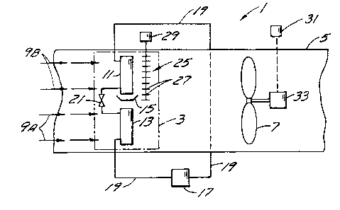
The dehumidifier 1 of the present invention, as shown
in Fig. 1, is of the type having a conditioning area 3 (shown
in dotted lines) in an air duct 5. Air is circulated from a
6.
2190316
room or area through the conditioning area 3 in the duct 5 by
an air mover 7, such as a fan or centrifugal blower, in the
direction shown by the arrows 9. In the conditioning area 3
there is an evaporator 11 located above a condenser 13. There
is also a drain pan 15 beneath the evaporator 11 and above the
condenser 13. The evaporator 11 is preferably located above the
condenser 13 so that the condenser will be less likely to
freeze up during operation of the dehumidifier. In some
installations, however, the evaporator 11 can be located below
the condenser 13.
During dehumidifying of the air, a compressor 17
compresses a refrigerant and passes it, as a hot gas and at
high pressure, through a line 19 to the condenser 13. In the
condenser 13, the refrigerant gas gives up heat to heat that
portion of the air, shown by the arrows 9A, passing over the
condenser 13 through the duct 5. The portion of the air is
heated so that all the air is returned to the room or area
being conditioned at a temperature slightly higher than the
normal temperature required in the area. The refrigerant, now
mostly liquid at moderate temperature and high pressure, passes
from the condenser 13 through a restrictor 21 where it expands
to a mixture of gas and liquid at low pressure and low
temperature. This refrigerant is then passed through the
evaporator 11 where it cools the remainder of the air, shown by
the arrows 9B, passing over it. As the remainder of the air is
7.
2t90316
cooled, moisture condenses from it onto the evaporator 11 and
collects in the drain pan 15. The refrigerant, now warmed by
the air to a vapour but still at relatively low temperature and
pressure, is returned to the compressor 17 by the line 19 for
compressing to repeat the cycle. The cooled air passing from
the evaporator 11 is mixed in the duct 5 with the warmer air
from the condenser 13 and returned to the room or area being
conditioned with less moisture than before. The unit described
is typical.
The moisture, as it condenses from the air passing
over the evaporator 11, can build up as ice on the evaporator
11 thus impairing its efficiency. When the ice buildup on the
evaporator 11 becomes too great for efficient operation, the
dehumidifier is defrosted. Defrosting is done by reversing the
flow of the refrigerant from the compressor 17 so that the hot
refrigerant gas passes through the evaporator 11 first from the
compressor 17. As the hot gas passes through the coils of the
evaporator 11, it melts the ice that has accumulated on the
evaporator. The water from the melting ice is collected in the
drain pan 15. During defrosting, the air mover 7 is turned off
so that the water from the melting ice is not picked up by the
air passing through the duct and returned to the room or area
being conditioned. The cooled refrigerant, leaving the
evaporator 11 and passing through the condenser 13, becomes a
mixture of liquid and gas and a liquid "slug" can be returned
8.
2190316
to the compressor 17 causing damage. To minimize the formation
of a liquid "slug", defrosting is performed more frequently
which lowers the efficiency of the humidifier. This defrosting
cycle is typical.
The present invention provides means for defrosting
the dehumidifier 1 in a much quicker and safer manner. In
accordance with the present invention, the air mover 7 is
operated during defrosting while blocking means 25 are also
operated to block the flow of air, shown by arrows 9B, over the
evaporator 11, and its associated drain pan 15 as shown in Fig.
2. Operation of the air mover 7 during defrosting causes it to
draw warm room air over the condenser 13. This warm air heats
the refrigerant in the condenser 13 to vaporize it and thus
eliminates the chance of a liquid "slug" damaging the
compressor 17 during defrosting. Heating the refrigerant also
makes the defrosting operation quicker and more efficient. The
blocking means 25 prevents the warm room air being drawn
through the duct 5 by the air mover 7 from passing over the
evaporator 11 and the drain pan 15 and this minimizes the warm
air picking up and returning moisture to the room.
The blocking means 25 for blocking the flow of air
over the evaporator 11 and drain pan 15 can comprise a set of
baffles 27 positioned adjacent the evaporator 11 and the drain
pan 15. The baffles 27 are open during normal operation of the
dehumidifier but are closed during defrosting. A suitable motor
29 can open or close the baffles 27. Suitable controls can be
9.
21903i6
provided to automatically close the baffles 27 by means of the
motor 29 during defrosting and to automatically open the
baffles 27 after defrosting is completed.
When the baffles 27 are closed during defrosting, as
shown in Fig. 2, the air flow through the duct 5, when the air
mover 7 is running, is channeled through the condenser 13 as
shown by the arrows 9A, 9B. This greater volume of air, at
increased speed, passing adjacent the bottom of the drain pan
15 and the evaporator 11, could still pick up moisture and
return it to the room. It is therefore preferred to reduce the
air flow over the condenser 13 during defrosting to minimize
the pick up of moisture from the drain pan and the evaporator.
Air flow control means are provided for reducing the flow of
air through the conditioning area 3 during defrosting while the
baffles 27 are closed. The air flow control means can comprise
a speed control 31 for a two speed motor 33 that runs the air
mover 7. The speed control means 31 can be automatically
operated when switching to the defrosting cycle to lower the
speed of the air mover. The speed of the air mover 7 can be
automatically reduced from 1800 rpm to 900 rpm, by way of
example, using the two speed motor.
Alternatively, the flow control means can comprise
one or more by-pass channels for passing a portion of the air
around the conditioning area 3 of the dehumidifier. For
example, as shown in Fig. 3, two by-pass channels 41, 43 can be
provided on either side of the duct 5 passing around the
10 .
2190316
-
conditioning area 3 located within the duct 5. The channels 41,
43 are each normally closed by a damper 45, 47 during normal
operation of the dehumidifier. During defrosting however, the
dampers 45, 47 are opened, as shown in Fig. 3, by motors (not
shown) to have some of the room air passing through the duct 5
bypass the conditioning area 3 as the air mover 7 continues
operation. The bypass channels 41, 43 are sized to bypass
approximately the same amount of air now being blocked by the
baffles 27 and more importantly, to by-pass enough air that the
remaining air passing through the conditioning area 3 and over
the condenser 13 does not pick up moisture from the evaporator
11 and drain pan 15 and carry it back into the room.
A different arrangement of by-pass channels from the one
shown in Fig. 3 can be employed. For example, two by-pass
channels can be employed, arranged one above the evaporator and
one below the condenser to bypass air around the conditioning
area.