Language selection

Search

Patent 2190484 Summary

Third-party information liability

Some of the information on this Web page has been provided by external sources. The Government of Canada is not responsible for the accuracy, reliability or currency of the information supplied by external sources. Users wishing to rely upon this information should consult directly with the source of the information. Content provided by external sources is not subject to official languages, privacy and accessibility requirements.

Claims and Abstract availability

Any discrepancies in the text and image of the Claims and Abstract are due to differing posting times. Text of the Claims and Abstract are posted:

  • At the time the application is open to public inspection;
  • At the time of issue of the patent (grant).
(12) Patent Application: (11) CA 2190484
(54) English Title: WATER DEPTH GAUGE
(54) French Title: INDICATEUR DE PROFONDEUR D'EAU
Status: Deemed Abandoned and Beyond the Period of Reinstatement - Pending Response to Notice of Disregarded Communication
Bibliographic Data
(51) International Patent Classification (IPC):
  • G01C 13/00 (2006.01)
  • A01K 91/20 (2006.01)
  • A01K 97/00 (2006.01)
  • G01K 3/14 (2006.01)
(72) Inventors :
  • STERNAL, BERND (Germany)
(73) Owners :
  • BERND STERNAL
(71) Applicants :
  • BERND STERNAL (Germany)
(74) Agent: SMART & BIGGAR LP
(74) Associate agent:
(45) Issued:
(86) PCT Filing Date: 1995-04-01
(87) Open to Public Inspection: 1995-11-02
Availability of licence: N/A
Dedicated to the Public: N/A
(25) Language of filing: English

Patent Cooperation Treaty (PCT): Yes
(86) PCT Filing Number: PCT/DE1995/000450
(87) International Publication Number: WO 1995029382
(85) National Entry: 1996-11-15

(30) Application Priority Data:
Application No. Country/Territory Date
P 44 13 727.3 (Germany) 1994-04-20
P 44 43 209.7 (Germany) 1994-12-05

Abstracts

English Abstract


The invention relates to a depth gauge for use in
angling or sports fishery. The depth of a body of water
may be measured therewith from its surface to its bottom,
and/or the depth and the size of strata of water of
different temperatures for the purpose of offering bait
to different species of fish in their preferred
environments, for instance at the bottom of a water or at
a thermocline stratum.
In accordance with the invention, a water-proof
housing a temperature sensor, a pressure sensor, a
digital evaluation circuit, a display and a program
switch are provided within a water-proof housing and
electrically interconnected in such a manner, that the
measurement value about the depth of the water to its
bottom and/or water strata marked by temperature
differences of more than 3° Kelvin are processed and
stored by the digital evaluation circuit. By means of
the program switch, the stored measurement data may be
called up and rendered visible in the display. In its
construction and configuration the depth gauge is
optimally suited for its intended use. It is light and
small, and it may be industrially manufactured with
little investment.


French Abstract

L'invention concerne un indicateur de profondeur d'eau s'utilisant dans la pêche à la ligne et la pêche sportive. Il permet de mesurer la profondeur de l'eau, de la surface de l'eau jusqu'au fond, et/ou l'épaisseur de couches d'eau présentant différentes températures, à l'intérieur des eaux, afin de pouvoir donner en pâture aux différentes variétés de poissons un appât leur correspondant, dans leurs zones de prédilection, par ex. au fond de l'eau ou dans des couches où la température varie. Selon l'invention, un boîtier étanche à l'eau comprend un détecteur de température, un détecteur de pression, un circuit d'évaluation numérique, un système d'affichage et un combinateur séquentiel agencés dans un boîtier étanche à l'eau, qui sont interconnectés de manière à ce que des valeurs mesurées sur des profondeurs allant jusqu'aux fonds subaquatiques et/ou des valeurs mesurées sur des couches d'eau caractérisées par des différences de températures supérieures à 3 Kelvin puissent être traitées et mémorisées par le circuit d'évaluation numérique. Un combinateur séquentiel permet d'appeler les données mesurées mémorisées et de les afficher. De par sa structure et sa forme, l'indicateur de profondeur d'eau convient optimalement à l'utilisation qui lui est dévolue. Petit et léger, il peut être produit de manière industrielle sans impliquer une grande complexité technique.

Claims

Note: Claims are shown in the official language in which they were submitted.

CLAIMS:
1. A depth gauge for measuring the depth of an angling
or sports fishing water from its surface to its bottom
and/or for measuring the depth and size of water strata
of different temperatures within such a water,
characterized by the fact that the same is submersible on
a line into the water, provided with a water-proof
housing (1,4) in which are arranged at least an
electrical pressure sensor (8), a display (10) with a
maximum storage, an electric battery (9) and a program
switch (11), the pressure sensor being unilaterally
connected to the environment of the housing (1) by at
least one pressure compensation aperture (2) or directly,
and pressure sensor (8), battery (9) and display (10) are
electrically interconnected in such a manner that the
measurement values from the pressure sensor (8) are
digitally indicated in the display (10) and remain
visible in the display (10) until manually reset by a
program switch (11), and further characterized by the
fact that aside from the pressure sensor (8), the display
(10), the electric battery (9) and the program switch
(11) there may be arranged in the housing (1) at least
one temperature sensor (7) and a digital evaluation
circuit (12) and interconnected with the pressure sensor
(8), the electric battery (9). the display (10) and the
program switch (11) and, if necessary, with other
electrical components, in such a manner that upon

submerging the depth gauge into the water the measurement
values of the temperature sensor (7) are processed by the
digital evaluation circuit in such a manner that upon the
occurrence of a temperature discontinuity, at a
temperature difference exceeding 3° Kelvin over a certain
distance in a temperature discontinuity, the depth of the
water is measured at that location and the measured value
is registered and stored, and where it remains visible
until manually reset by the program switch (11).
2. The depth gauge of claim 1, characterized by the
fact that the digital evaluation circuit (12) processes
and stores in the measurement data storage a plurality of
measurement data such as depth of the water, thermocline
depth, upper and lower temperature of the thermocline,
size of the thermocline as well as temperatures
prevailing at different depths of the water, and that
these measurement values may be called up by the program
switch (11) and rendered visible in the display (10).
3. The depth gauge of claim 1 and 2, characterized by
the fact that at least one eyelet (9) or a bore is
provided on the housing (1) for affixing an angle or
plumb line.
4. The depth gauge of claim 1 to 3, characterized by
the fact that changeable ballasts preferably of different
ballasts are provided in the housing (1) or on the
housing (1,4).
5. The depth gauge of claim 1 to 4, characterized by

the fact that the housing (4) contains a cavity
threadedly connectable with the housing (1) for receiving
ballasts (5).
6. The depth gauge of claim 5, characterized by the
fact that the housing (4) is provided with at least one
pressure compensation aperture (3).

Description

Note: Descriptions are shown in the official language in which they were submitted.


--.
,`.LE, ~*fil T, .~ ..3EEL
' I~TRA~`~S~T~Oi!l
21 93~84
~ttcrney ~ocket 96016a
Depth Gauge
The invention relates to a depth gauge for use in
angling and sports fishing. It i8~ used to meaæure the
depth of a body of water from lts surface to its bottom,
10 or the depth of strata of water of different temperatures
within a body of water.
A digital depth gauge with a piezoresistive pressure
recording (Dr lrkAl~fn~l ), integral illumination and zero
15 point correction is known for divers for diving in
- lnt~1n lakes having depths up to 200 m ~German patent
specification 31 45 158 A1) .
Owing to its structure, it3 size and its weight, as
20 well as, in particular, its elaborate set-up, this
apparatus is unsuita~le for anglers and sports fishermen.
An apparatus is known for detecting the profile of
the bott~m of waters which in essence consists of a
25 pressure measuring capsule adapted to be moved by a line
on thé bottom of the water in direct contact therewith,
the measured values of which are ~nnt; nllnusly transmitted
to an interpretins station by a connection (German
utility model 76 05 605.8). This apparatus is utilized
30 particularly in the preparation of ariueous construction
operations and is unsuitable in sports fishery.
For angling and sports fishing, species-specific
_ _ . . . . . .

21 90~84
bait has to be ofered to a fish in its respective
environment, for which purpose the depth of the water has
to be correctly determined by the angler or sports
fisherman. At present, this is done by repeatedly
5 sinking and retrievi~g a ground lead (sinker) on a
fishing line and a quill spaced therefrom, and by
resetting the distance between sinker and quill until the
distance between the bottDm of the water and the surf ace
of the water is rP~ ngn; 7~hle by the position of the
10 quill. This is a tedious and time-consuming procedure
which because of the frequent casting of the sinker may
lead to any fish being chased away.
It is known that in almost all bodies of waters
15 there are strata or currents of cold and warm water. At
the interfacial zones of such layers of water, i . e . at
those positions at which the cold and warm water strata
converge, there exist temperature differences of several
degrees Kelvin. Such strata are known to anglers and
20 sports ishermen as thermoclines. These thermoclines are
of particular.importance to the angler or sports fisher-
man because it is these strata whic~l are often frequented
by predatory fish. Thereore, the angler and sports
fisherman favors placing his bait as precisely as
25 possible at or in these thermoclines.
Unless the very elaborate procedure for detl~rmln;n~
these thermoclines is wholly dispensed with and angling
is to be undertaken on the basis of "pure luck~, this
3 0 thermocline can only be f athomed with a thermometer .
This is done by systematically and frequently placing a

3 2} q~4~4
thermometer at different depths of the water, and
retrieving it for reading, until the approximate depth of
the searched-for thermocline~ has been determined an the
basis of a pre~etermined discontinuity in temperature.
The use of a known thp ter for this purpose 18
disadvantageous because of the disproportionately
elaborate e~fort, which is why anglers and sports
fishermen usually dispense with determining thermoclines
10 in the waters. In the event, the ~n~n;r~ tion of a
thermometer for fathoming thermoclines is only possible
from a boat/ so that from the land the angler has no
possibility whatever for detecting thermoclines
It is an obj ect of the inve~tion to provide a depth
gauge for anglers and sports fishermen which useful for
measuring the depth of a body of water from the surface
thereof to its bottom and/or for detecting the depths of
layers of water of different temperatures, and which is
simple and handy, which deIivers reliable measurement
values in the range of relatively shallow depths of
water, and which may be manufactured with little
investment in a cost efficient manner.
In accordance with the invention the object is
accomplished by arranging, within a water-proof housing,
at least an elcctrical pressure se-nsor, a display
including a maximum storage, an electrical battery and a
program switch, the pressure sensor being connected to
the P2~tPr; nr- of the housing unilaterally by at least one
pressure compensatio~ aperture or directly, the pressure

2 1 90484
sensor, battery, program switch and display being
electrically interconnected in a conv~nt;nn~l manner such
that the measurement values of the pressure sensor~ are
rendered visible in by the display and remain visible in
5 the display until manually reset by the program switch.
In addition, at least one electrical temperature
sensor and o~e digital evaluation circuit may be arranged
within the housing which in a known manner may, if
10 required, be connected to other electronic components
such that the measuring values f rom the temperature
sensors may be evaluated by the digital evaluation
circuit as the depth gauge is bei~g submerged such that
at an occurrence of a temperature discontinuity exceeding
15 3~ Kelvin over a certain distance, the depth of the water
at that Iocation is measured and recorded. Also, the
measured value is rendered visible in the display where
it remains vislble until manually reset by the program
switch .
In one elllbodiment of the invention the digital
evaluation cir-cuit may be conventionally interconnected
with the measurlng transducers, pressuré se~sor and
temperature sensor, a measurement value storage, the
25 program switch as well as the display in such a manner
that different measured values representing water depth,
the depth of the thermocline and its size, the upper and
lower temperature of the thermocline as well as
temperatures prevailing at different depths can be stored
30 and that these measured values may be rendered visible in
the display by manual program switching.
.

21 90484
The housing i8 provided with an eyelet and a bore
for attaching a f ishing line or a plumb line . The
housing ~ay also consist of two threadedly rrnnl~rtAhle
portions, one housing portion being structured as a
!~ cavity for receiving ballasts of similar or different
weir,hts. For practical purposes, the cavity is provided
with apertures for the compensation of pressure.
Alternatively, the ballasts may be structured as
10 parts fitting the housing and may be attached to the
exterior of the housing.
The depth gauge in accordance with the invention i8
optimally structured to accommodate its intended purpose.
15 It is small and light, simple to u e and reliable in its
perfortnance. The use of such an apparatus reduces the
e~fort involved i~ preparing for angling and improves the
possibility of success and, hence, the enjoyment of
leisure time.
The depth gauge may be manufactured in different
variants with relatively small investment and at a
reasonable ratio of price and perfol-mance.
The i~vention will hereinafter be explained in
greater detail. Example 1 relates to measuring of the
bottom of a water body and example 2 relates to the
mea~uring of thermoclines.
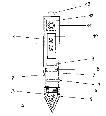
The drawing is a schematic rendition of the depth
gauge in accordance with the invention
-

21 90484
13xample 1
The housings 1, 4 ' are screwed together by threading
6. The housing 4 is structured as a cavity and is
5 provided with pressure compensation apertures 3.
The housing 1 contains a pressure sensitive
electrical pressure sensor 8, an electrlc battery 9, a
display 10 and a program switch 11.
The pressure sensor 8 seals the housing 1
unilaterally relative to a chamber provlded with pressure
compensation apertures 2. An eyelet 13 is arranged on
the housing 1. Pressure sensor 8,=battery 9 and display
15 10 are electrically interconnected in a conventional way
and calibrated such that changes in pressure registered
by the pressure sensor 8 are rendered visible on a scale
in the display 10, and remain visible by virtue of a
maximum storage until the indication in the display 10 is
20 manually reset.
.
For using the depth gauge, it is attached to a
f ishing line by the eyelet 13 . The housings 1 and 4 are
separated, and the cavity of the housing 4 is f illed with
25 ballasts 5 as determined by the angler. The housings 1
and 4 are then ~olned again, and the display 10 is set to
zero by the program switch 11.
The depth gauge affixed to the fishing line is now
30 sunk to the bottom of the water at the location to be
measured, with the water pressure which is proportioral

21 904~4
to the depth of the water acting on the pressure sensor 8
through the pressure compensation apertures 2, rendering
the measured value visible in the display 10 by means of
the electric circuitry. By means of the maximum storage
5 the measured value will remain visible in the display 10
until the depth gauge is withdrawn-from the water, has
been read by the angler and reset by the program switch
11. On the basis, of the measured value the relationship
between the b~it and the quill may now be set precieely
10 and in accordance with the species of fish to be caught.
Example 2
The housing 1 is threadedly connected to the housing
15 portion 4. The housing portion 4 is hollow and is
provided with pressure compensation apertures 3. It may
be charged with ballasts 5.
In the housing, there are provided an electrical
2 0 pressure sensor 8, an electrical temperature sensor 7, a
digital evaluation circuit 12, an electric battery 9, a
program switch actuable from the exterior, and a display
10 as well as apertures 2 for the pressure sensor 8 and
the aperture for the temperature sensor 7. The electric,
25 electronic and mechanical structural units or components
are electrically interconnected in a conventional manner
in such a way that measured value~ f rom the pressure
sensor 8 and from the temperature sensor 7 may be
processed and stored by the digital evaluation circuit
30 12. Different stored measured values processed by the
evaluation circuit 12 measured values may be called up by

21 9~484
the externally actuable program switch 11 ~rom the
measuring data storage, and rendered visible in the
display 10.
On top of the housing 1 there is provided an eyelet
13 for affixing a plumb line.
For use, the depth gauge is affixed to a fishing or
plumb line by the eyelet 13, activated by the program
switch 11, and sunk into the water. The values measured
by the pressure and temperature sen~ors 7; 8 are
processed by the digital evaluation circuit 12 and the
depth at which a temperature disr~n~;n-l;ty of more then
3 Kelvin occurs is particularly registered and stored .
When retrieving the depth gauge mea~urement data of
the deepest measuring point of the water are no longer
registered and stored. The mea~urement data processed
and stored by the digital evaluation circuit 12, in
particular the discontinuity in temperature at a measured
depth, can now be called up from the data storage by the
program switch 11 and rendered ~isible in the display 10,
when the depth gauge has been retrieved f rom the water .
- On the basis of this data, the angler may now place
his species-sFecific bait for fish assumed at or in the
thermocline and thus inf luence his chances of success in
a positive manner. - - ~

Representative Drawing
A single figure which represents the drawing illustrating the invention.
Administrative Status

2024-08-01:As part of the Next Generation Patents (NGP) transition, the Canadian Patents Database (CPD) now contains a more detailed Event History, which replicates the Event Log of our new back-office solution.

Please note that "Inactive:" events refers to events no longer in use in our new back-office solution.

For a clearer understanding of the status of the application/patent presented on this page, the site Disclaimer , as well as the definitions for Patent , Event History , Maintenance Fee  and Payment History  should be consulted.

Event History

Description Date
Inactive: IPC from MCD 2006-03-12
Time Limit for Reversal Expired 2001-04-02
Application Not Reinstated by Deadline 2001-04-02
Deemed Abandoned - Failure to Respond to Maintenance Fee Notice 2000-04-03
Application Published (Open to Public Inspection) 1995-11-02

Abandonment History

Abandonment Date Reason Reinstatement Date
2000-04-03

Maintenance Fee

The last payment was received on 1999-03-01

Note : If the full payment has not been received on or before the date indicated, a further fee may be required which may be one of the following

  • the reinstatement fee;
  • the late payment fee; or
  • additional fee to reverse deemed expiry.

Please refer to the CIPO Patent Fees web page to see all current fee amounts.

Fee History

Fee Type Anniversary Year Due Date Paid Date
MF (application, 3rd anniv.) - small 03 1998-04-01 1998-04-01
MF (application, 4th anniv.) - small 04 1999-04-01 1999-03-01
Owners on Record

Note: Records showing the ownership history in alphabetical order.

Current Owners on Record
BERND STERNAL
Past Owners on Record
None
Past Owners that do not appear in the "Owners on Record" listing will appear in other documentation within the application.
Documents

To view selected files, please enter reCAPTCHA code :


To view images, click a link in the Document Description column. To download the documents, select one or more checkboxes in the first column and then click the "Download Selected in PDF format (Zip Archive)" or the "Download Selected as Single PDF" button.

List of published and non-published patent-specific documents on the CPD .

If you have any difficulty accessing content, you can call the Client Service Centre at 1-866-997-1936 or send them an e-mail at CIPO Client Service Centre.


Document
Description 
Date
(yyyy-mm-dd) 
Number of pages   Size of Image (KB) 
Cover Page 1997-04-14 1 15
Abstract 1995-11-02 1 31
Claims 1995-11-02 3 81
Description 1995-11-02 8 285
Drawings 1995-11-02 1 9
Representative drawing 1999-06-10 1 8
Courtesy - Abandonment Letter (Maintenance Fee) 2000-05-01 1 183
Fees 1997-03-14 1 59
International preliminary examination report 1996-11-15 35 1,184
Courtesy - Office Letter 1996-12-02 1 21