Note: Descriptions are shown in the official language in which they were submitted.
CA 02190491 2004-05-10
MATERIAL AND METHOD FOR FORMING
AN UNDERWATER BARRIER LAYER
BACKGROUND OF THE INVENTION
1. Field of the Invention
The invention relates generally to materials and methods for forming
barrier layers and, more particularly, to a material and method for forming a
barrier layer over a contaminated, underwater surface.
2. Summary of Related Art
A significant number of lakes, ponds, marshes, river beds and the like
are contaminated with environmentally hazardous materials. Examples of
such materials include polychlorinated biphenyls, or PCBs, white
phosphorus, and metals. Many of these materials, once introduced by one
means or another, settle on the bottoms of such bodies of water. This
contaminated sediment is detrimental to the wildlife which utilizes the body
of
water, especially to the fish and foraging waterfowl.
In some cases, it is not feasible to remove or treat such
sediment in situ. Thus, to prevent the wildlife from coming into
contact with the contaminated sediment, it has been proposed
to form a barrier layer over the contaminated sediment. To
accomplish that, various plastic membrane barrier systems have
been used previously. Such systems typically include a plastic
WO 95131609 PCTIUS95106124
2i 90~~91
2
membrane which is positioned on the bottom of the body
of water with a layer of sand or similar material over
the top of the plastic membrane to hold it in position.
A number of venting pipes are usually required to permit '
the venting of gases which build up beneath the plastic
membrane. These plastic membrane-systems are relatively
difficult and expensive to install. In addition, the
plastic membranes are relatively easily punctured and
are susceptible to cracking in response to the large
to temperature changes experienced in many underwater
environments.
It would therefore be desirable to provide a
relatively simple and inexpensive material for forming a
barrier layer over a contaminated, underwater surface
1s which is durable under varied-temperature conditions.
It would further be desirable to provide such a material
which forms a barrier layer which is not susceptible to
puncture or cracking and which does not require a
venting system. It would also be desirable to provide
2o an improved method of forming such a barrier layer.
SiJ~IMARY OF THE INVENTION
The invention relates to a bead for forming a
barrier layer over an underwater surface. A plurality
2s of such beads are generally required to form an
effective underwater barrier layer. Each of the beads
comprises a core which is preferably formed of a piece
of gravel. A sealant layer is provided which at least
r
partially encapsulates the core of the bead. The
3o sealant layer includes a clay and a binder. The binder
helps to adhere the sealant layer to the core of the
bead.
W0 95/31609 219 0 4 ~ 1 P~~S95/06I24
3
To form such an underwater barrier layer over
contaminated sediments beneath a body of water, a
plurality of the beads are deposited on top of the
~ contaminated sediments. Once the beads are submerged,
s the sealant layer about each of the beads begins to
absorb water and swell. A continuous layer of the clay
and binder is thus formed, with the cores of the beads
dispersed randomly throughout this layer.
The beads of the invention may also be used to form
io barrier layers in the presence of water in a variety of
other applications. For instance, a plurality of the
beads may be introduced into an annular well space
formed between the ground and the well casing, typically
formed of steel or plastic. Preferably, the entire
1s annular space is filled with beads. If the annular
space is dry, water is added. Once the beads are
submerged, the sealant layer about each of the beads
begins to absorb water and swell, and a continuous
annular layer of the clay and binder is formed.
2o Various objects and advantages of the invention
will become readily apparent to those skilled in the art
from the following detailed description of a preferred
embodiment when considered in the light of the
accompanying drawings.
2s
BRIEF DESCRIPTION OF THE DR_AWTNrc
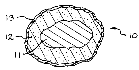
Fig. 1 is a sectional view of a single bead of the
material for forming a barrier layer in accordance with
this invention.
3o Fig. 2 is a sectional view of the barrier layer
formed by the material and method of the invention.
WO 95/31609 PCTIUS95106124
2190491
4
DESCRIPTION OF THE PREFERRED EM&ODIMENT
Referring now to the drawings, Fig. 1 illustrates a .
bead, indicated generally at 10, of the material for -
forming a barrier-layer in accordance with this
s invention. As will be discussed in detail below, a
plurality of such beads 10 are typically requiredto
form an effective underwater barrier layer.- The bead 10
is formed of a core-ll which is at least partially
encapsulated by a sealant layer 12. The core 11 is
1o preferably completely encapsulated by the sealing layer
12. In a preferred embodiment, a protective coating 13
is provided over the sealant layer 12.
The core 11 of-the bead 10 is formed of a piece of
a material which is relatively hard and dense when
1s compared to the sealant layer 12. Examples of-suitable
materials for forming the core 11 include pieces of
stone, iron ore, slag or crushed porcelain. Preferably,
the core 11 of each bead 10 is formed of a piece of
gravel. Gravel of a variety of sizes will pack together
2o very well in the barrier layer.
As mentioned above, the core 11 is encapsulated by
a sealant layer 12. The sealant layer 12 includes a
clay material, or a mixture of clay materials, which
exhibits a high absorption and swelling capacity.
as Preferably, the clay is a bentonite clay which is
readily hydratable, such as calcium bentonite or sodium
bentonite. In certain applications, especially in water
having a relatively high salt content, the preferred
clay is attipulgite clay. In a preferred embodiment,
3o the sealant layer 12 may also include one or more -
organically modified clays, which also are referred-to
as organo clays. Such organo clays may be effective in
WO 95/31609 PCTlfJS95/06I24
binding with some contaminants, such as most metals,
which come into contact with them. The organo clays can
be innoculated with bacteria that comsume pollutants.
The sealant layer 12 also includes a binder to
s promote the adhesion of the clay to the core 11 of the
bead 10. An amount of the binder-sufficient to bind the
clay to the core 11 is mixed with the clay.
Alternatively, a layer of the binder may be interposed
between the clay and the core 11. The binder is
io preferably a polymeric material, such as a cellulosic
polymer. A preferred binder is guar gum. Plastic fiber
can also be mixed with the clay as a binder. Lime dust
or cement can also be used as a binder.
The sealant layer 12 may also include a setting
material, such as gypsum or plaster o~ paris, which sets
with water. This material is preferably mixed with the
clay or mixture of clays forming the sealant layer, and
may comprise up to 90~ of the sealant layer 12 by
weight.
2o A bird aversion agent may also be added to the
beads 10. Suitable bird aversion agents include esters
of anthranilic acid, esters of phenylacetic acid, or
dimethyl benzyl carbinyl acetate, as examples.
Preferred bird aversion agents are dimethyl anthranilate
and methyl anthranilate. These bird aversion agents are
preferably mixed in with the binder in amounts
sufficient to repel foraging waterfowl which would come
into contact therewith.
The bead 1D may be provided with an outer coating
13 which aids in keeping the sealant layer 12 intact
prior to the deposition of the bead 10 on an underwater
surface. Preferably, the bead is provided with a thin
CA 02190491 2004-05-10
6
polymeric protective coating 13 about the sealant layer 12. A preferred
material for the protective coating 13 is an acrylic resin. A latex, or a
gypsum
in water slurry, are additional examples of suitable materials for the
protective coating 13. The protective coating 13 should not be of a thickness,
dependent upon the particular material, which would prevent the eventual
hydration of the sealant layer 12 of the bead 10 after the bead 10 is placed
underwater.
The beads 10 in accordance with the invention may be formed in any
suitable manner. Preferably, the binder is placed into an aqueous solution
and mixed with the clay. A number of the cores 11 are added to this sealant
mixture and stirred so that the sealant mixture adheres to the each of the
cores 11. The sealant mixture may be allowed to dry about the cores 11, and
then stirred with additional sealant mixture to form a multi-layered sealant
layer 12 about each of the cores 11. The protective coating 13 may then be
applied by any suitable means, such as by spraying.
An underwater barrier layer 20 formed from the beads 10 of this
invention is illustrated in Fig. 2. The underwater barrier layer 20 covers a
layer of contaminated sediments 21 which lies beneath a body of water 22.
To form this barrier layer 20, a plurality of the beads 10 are deposited on
top
of the contaminated sediments 21. If the contaminated sediments 21 are
underwater at the time of the deposition, the beads 10 may be dropped
directly into the water 22. The beads 10 will sink, settling on top of the
contaminated sediments 21. Since the beads 10 are relatively hard
and impact resistant, they may be dropped into the water from the
30
W O 95/31609 PC'TlUS95/06124
2190491
air, such as from a helicopter drop bucket. The beads
- 10 may also be pumped out over the contaminated
sediments 21 using a conventional pump. Alternatively,
~ if the climate permits, the beads 10 may be deposited
s when the water above the contaminated sediments 21 is
frozen. The beads 10 may then be effectively deposited
by means of a truck, road grader, low ground pressure
bulldozer, or other suitable means. When the ice melts,
the beads 10 will sink to the bottom, settling on top of
1o the contaminated sediments 21.
Once the beads 10 are submerged, the sealant layer
12 about each of the beads 10 begins to absorb the water
and to swell. A continuous layer of the clay and binder
is thus formed, with the cores 11 dispersed randomly
15 throughout. it is believed that the cores 11 aid in
keeping the barrier layer 20 intact on top of the
contaminated sediments 21. If a setting material such
as gypsum or plaster of paris is included in the sealant
layer 12 of the beads 10, this material will set when
zo hydrated.
A sufficient number of the beads 10 are deposited
over the area to form a physical barrier layer 20 of a
thickness sufficient to prevent the migration of the
contaminated sediments 21 into the water 22. Generally,
zs a barrier layer 20 of a thickness of between about 4 to
8 cm is adequate to prevent the migration of
contaminated sediments therethrough, as well as to
prevent the animals and other organisms using that body
of water from coming into contact with the sediments 21.
3o Where a bird aversion agent has been added to the beads
10, it will be dispersed throughout the barrier layer
20, further discouraging foraging waterfowl from coming
WO 95131609 2 T 9 0 4 91 P~~S95106124
8
into contact with the contaminated sediments 21 beneath
the barrier layer 20.
If desired, additional pelletized material may also
be mixed with the beads 10 prior to their deposition on
s the contaminated sediments 21. Examples of such
materials include pelletized fertilizer, sewage, sludge,
cement kiln dust, lime, recycled plastic, corn cobs,
flyash, sawdust and recycled paper. These additional
pelletized materials help to provide a medium for seed
1o germination and plant growth within the barrier layer
20.
A cover layer 23 may also be provided over the
barrier-layer 20 to minimize the dissipation of the clay
into the water 22, thereby effectively increasing the
1s useful life of the barrier layer 20. Such a cover layer
23 may be formed of a layer of aggregate, such as gravel
or sand, which also promotes the growth of vegetation.
In a preferred embodiment, the cover layer 23 is formed
of an additional layer of the beads 10 which include a
2o setting material such as gypsum or plaster of paris in
the sealant layers 12 thereof. The setting material
will quickly set when hydrated to form a hard layer over
the barrier layer 20, thereby preventing any dissipation -
thereof into the water 22.
2s As mentioned above, the beads 10 of the invention
may also be used to form barrier layers in the presence
of water in a variety of other applications. For
instance, a plurality of the beads 10 may be introduced
into an annular well space formed between the ground and
3o a well casing, typically formed of-steel or plastic.
Preferably, the entire annular space is filled with
beads. If the annular space is dry, water is added
WO 95/31609 219 0 4 91 PCT~S95/06124
9
thereto. Once the beads are submerged, the sealant
layer about each of the beads 10 begins to absorb water
and swell, and a continuous annular layer of the clay
and binder is formed.
s In accordance with the provisions of the patent
statutes, the present invention has been described in
what is considered to represent its preferred
embodiment. However, it should be noted that the
invention can be practiced otherwise than as
1o specifically illustrated and described without departing
from its spirit or scope.