Note: Descriptions are shown in the official language in which they were submitted.
2190557
1
- PROCESS FOR MAKING A COMPOSITE ROTOR WITH METALLIC
MATRIX
DESCRIPTION
This invention concerns a process for making a
composite rotor with metallic matrix.
Rotor parts formed from a single block starting
from a metallic matrix which is then machined into the
required shape, are fairly frequently used.
Another idea was to reinforce the matrix, which
'is often formed of a brittle alloy such as titanium and
aluminum, by fibers wound in internal circles embedded
in the matrix around the spindle of the rotor.
These fibers have a higher breaking strength
than the matrix and a higher modulus of elasticity, and
can be used to build strong high performance and fairly
lightweight rotors. They are usually wound around a
rotor hub and are embedded in the metallic matrix.
Metallic material with exactly the same composition as
the matrix is added between the fiber windings to give
good cohesion. Therefore the manufacturing method
requires that fiber windings are formed, that these
windings are placed in the matrix material and that the
assembly is combined by hot compression, causing
agglomeration between the fibers and the matrix while
eliminating interstices between the windings and the
added rrretallic material. However, the fiber must be
protected from swelling, i.e. irregular displacements
of windings which would disturb the regularity of their
position in the finished part.
It has been demonstrated that if a tensile
breaking test is carried out along the direction of the
fibers on a part with this~type of composition, the
part normally fails due to a lack of shear cohesion at
the bond between the matrix and the fibers, between two
SP 10466 JCI
219057
2
failure planes of two adjacent fibers; this failure
mode absorbs a large amount of energy, but only occurs
- if fibers are uniformly distributed. Otherwise, stress
concentrations created close to a fiber extend to reach
its neighbors if they are close by, with the
consequence that they too will break almost
immediately. It is observed that the failure
propagates across the entire test piece on a plane, at
a fairly low force and without the matrix material
making a significant contribution to the strength.
Therefore, a number. of processes have been
'designed to obtain a uniform layout of fiber windings.
In the first process, the fiber is wound layer by layer
around a mandrel and the material added to the matrix
is sprayed as plasma between the turns of the exposed
layer. Oblique projections in both directions are
necessary to satisfactorily fill in the interstices
between turns, and then additional spraying is
necessary to cover the turns. This is difficult in
practice and complicated.
Another idea was to place the material added to
the matrix in the form of metal foil alternating with
the layers of fiber turns. The metal strips could then
be wound directly on the manufacturing machine, or the
structure could be prepared by placing alternating flat
layers of metal foil and fiber cable strips, and the
winding being done in the next stage. But
manufacturing difficulties were encountered with this
system, in joining the ends of metal foil to prevent
them from folding and to make uniform overlaps, in
particular without allowing fibers to slide during
winding. Stress concentrations due to structure
irregularities were observed on finished parts.
Depositing alternating helical layers of fiber
and metal strip as proposed in French patent 2 607 071
has similar disadvantages.
SP 10466 JCI
2190557
3
Finally, another idea was to deposit the
material added on the matrix onto the fiber before
forming the windings and then apply an isostatic
compression to the assembly when hat. This process is
described in French patent 2 684 578. It is easier in
practice, but does not entirely eliminate uniformity
defects on the part structure.
The origin of the invention may be seen more
easily in the idea that hot isostatic compression also
contributed to the appearance of structure
irregularities, regardless of the process chosen for
'winding and the care taken in its execution.
Elimination of the interstices implies that windings
are tightened, and therefore that their diameter
contracts causing fiber buckling deformations.
The characteristic of the invention is that it
avoids these contractions of turn diameters and their
consequences by means of enhanced hot compression
exerted in the axial direction only.
However, perfect uniformity of the windings
must also be guaranteed to prevent any swelling during
hot compression, which is very difficult due to the
fineness of the fibers which have a diameter of the
order of 50 microns: therefore the fibers are very
flexible and they have a large number of windings. A
process for placing windings that are reliable and easy
to use in industry would therefore be desirable; it is
described below and also forms part of the invention.
The rotor with metallic matrix including fiber
windings that are finally obtained, forms a unique and
compact mass with much more uniformly positioned fiber
windings.
The process according to the invention includes
the following steps:
- build a metal hub consisting of a plate and a rod
placed upright on the plate,
SP 10466 JCI
2190567
4
place a metal disk on the rod, a metal cap being
connected to the disk and extending around the disk,
then:
- wind the fibers coated with the matrix material
S around the rod and between the disk and the plate,
- place a metal bushing around the plate and the
fibers, the cap projecting beyond the bushing and the
rod, and release the disk cap,
- surround the hub, the bushing and the cap, using a
duct fitted with a degassing orifice,
- compress the duct by hot isostatic compression until
the cap penetrates and reaches a given level,
- remove the duct and, if necessary, machine the
metallic block into a required shape.
Therefore the block is formed by the
agglomeration resulting from isothermal forging of the
hub, the bushing, the cap and the fiber coating, which
are normally formed from the same matrix material, and
form a single block at the end of the process. The
fibers continue to bond to their coating and are
therefore perfectly integrated into the formed part.
The invention will now be described in more
detail with reference to the following figures that
describe one possible embodiment and are supplied for
illustrative and non-restrictive purposes:
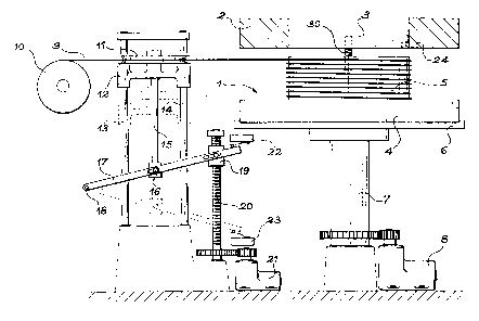
~ figures 1, 2, 3 and 4 represent four
production steps.
wThe metallic matrix is initially formed from
-- four pieces, three of which are visible in figure l,
namely a hub 1, a cap 2 and a disk 3. The hub 1 is
formed from a lower circular plate 4, to which a
cylindrical rod 5 is fixed upright at the center. The
cap 2 has a slightly larger diameter than rod S, and an
external diameter identical to that of plate 4. The
3S diameter of disk 3 is similar to the diameter of rod S.
The first step is to place disk 3 on rod S and cao 2
SP 10466 JCI
2190567
around disk 3 so that it can slide around it and around
rod 5, and plate 4 is placed on a support 6 such. that
it is coaxial with a spindle 7 on which support 6 is
fixed, in the same way as cap 2, disk 3, and rod 5. A
5 motor 8 rotates spindle 7.
A f fiber 9 was prepared . I t i s unwound from a
reel 10 turning freely, and it is passed around a
pulley 11 rotating freely on a frame 12 itself mobile
in translation along two vertical and parallel slides
13 and 14. The frame 12 is connected by a connecting
rod 15 to an intermediate point 16 of a lever 17, one
'end of which is hinged to a fixed point 18 and the
other end to a nut 19 free to move along a vertical
lifting screw 20 driven by a motor 21. Two switches 22
and 23 sensitive to the connecting rod 17 contact are
provided adjacent to the lifting screw 20 to form limit
switches.
Fiber 9 is moved forwards by rotating motor 8,
which unwinds it from reel 10 forming windings around
rod S. At the same time, motor 21 starts to slowly
lower connecting rod 17 and therefore pulley 11 from
the upper switch 22 to the lower switch 23. The pulley
11 gradually draws fiber 9 downwards.and contributes to
forming windings over the entire height of rod 5,
between disk 3 and the plate. In this embodiment, the
end of fiber 9 is trapped between disk 3 and the upper
surface of the rod S, but other methods could be
considered for drawing the fiber by fixing it to parts
1, 2 and 3 of the matrix. The height of cap 2 exceeds
the height of disk 3, and it is held in place so that
it proj ects upwards around it by a retaining dowel 24
housed in a cavity formed in the lower surfaces of the
cap 2 and disk 3. Another dowel 30 is used to center
disk 3 on rod 5; this dowel is housed in a cavity
formed on the spindle of these parts. But there are
other ways of making this assembly: thus cap 2 can
SP 10466 JCI
2190567
6
clamp disk 3 slightly and project slightly below it, at
the top of the rod 5 which itself controls centering.
The centering dowel 30 may be chosen with a diameter
sufficient to drive disk 3 in rotation. In another
possible embodiment, spindle 7 is replaced by a thinner
spindle onto which hub 1 and disk 2 are slid, through
the drillings in their centers. Unlike previous
processes which are more difficult to accomplish, this
process guarantees very uniform windings without the
need for any dexterity. Cap 2 acts as a reel during
winding and therefore prevents the wound layers from
moving .
Fiber 9 is cut when the windings are made. The
result is the state illustrated in figure 2. The
centering dowel 24 is withdrawn and a bushing 26 is
slid into position, which is the fourth part of the
metallic matrix, around cap 2, windings 25 and plate 4;
a hermetically sealed duct 27 is then formed around the
entire matrix, however after drilling a degassing duct
28 leading to pump 29. Note that when bushing 26 is
placed at the same height as plate 4, its top is at the
same height as disk 3 but cap 2 projects above it.
A hot isostatic compression is then made to
produce a compact mass in duct 27, as shown in figure
3. Hot isostatic compression processes are now well
known and will not be mentioned further. In this case,
the main effect obtained is an agglomeration of
windings 25 resulting in a reduction of their volume
and a gradual collapse of cap 2. The isostatic
compression becomes a purely axial compression of
windings 25 due to the continuity of bushing 26, which
replaces a circle of cores used in earlier processes
and which contract radially until the cores touch. The
disadvantages of this radial'compression for uniformity
of windings 25 have already been mentioned. Swelling
of the fiber is much less with the invention. It is
SP 10466 JCI
' 219567
7
beneficial if the height of the cap 2 is calculated so
that its upper surface is flush with the upper surfaces
of disk 3 and bushing 26 when satisfactory
agglomeration of windings 25 has been achieved, as
shown in figure 3. The compression can then be
stopped.
Finally, and in accordance with figure 4, duct
27 is formed by machining and the metallic matrix
corresponding to the old parts 1, 2, 3 and 26 may be
machined as necessary to form the required part.
. A recess can then be formed in its spindle to
form a reaming 30, and material can be removed from its
external periphery so that only the blades 31 remain;
more generally, the part may be machined as necessary.
Note that there is a great deal of freedom as a
function of the required final shape. As an
alternative, parts l, 2, 3 and 26 may be designed at
the beginning with an external surface similar to the
external surface of the part in its final condition;
duct 27 will then have an appropriate shape.
One typical manufacturing example concerns a
TAGV alloy matrix and silicon carbide SiC fibers also
coated with titanium. Coatings of windings 25 form
compact mass during compression. Perfect cohesion of
the part is thus obtained.
SP 10466 JCI