Note: Descriptions are shown in the official language in which they were submitted.
CA 02191007 2001-04-24
METHOD AND DEVICE FOR WINDING A MATERIAL WEB
The invention relates to a method for winding a material web, in particular a
paper web, in
which the material web is wound onto a spool or equivalent through a winding
nip formed between
a cylinder, roll or equivalent and the roll that is being formed about the
spool or equivalent roll core.
Further, the invention relates to a device for winding a material web, in
particular a paper web,
in which the web is wound onto a spool or equivalent through a winding nip
formed between the roll
that is being formed and a cylinder, roll or equivalent.
1n the prior art, web winders are known, for example carrier-drum slitter-
winders and Pope-
type winders, by whose means a material web is wound through a winding nip
formed between a
drum and the roll that is being formed. It is also known in the prior art to
provide a carrier-drum
slitter-winder with air relief.
With respect to the prior art related to such constructions, reference is
made, for example, to
Finnish Patent Application No. 921789 which describes a support-roll winding
machine for winding
a material web that has been divided by slitting onto spools without shafts.
In the winding machine,
there are two support rolls on which the winding rolls rest during the winding
operation. In this
arrangement, there are means for sealing the space formed by the support rolls
and the winding rolls
and for forming a pressure in that space.
Figure 4A illustrates a prior art carrier-drum slitter-winder with air relief.
In this prior art
219 ~ 007
construction, the air relief is provided by means of a pressure PZ produced
between the carrier drums
11,12 and the roll 10 being formed. However, the generation of this pressure
increases the problem
which always occurs in high-speed winding of a material web W, as well as in
other situations, i.e.,
the penetration of air through the winding nip between the material web W that
is being wound and
the material that is akeady present on the roll 10. These problems are
emphasized in particular when
material webs are being wound that are poorly penetrable by gas.
The entry of air between the web being wound and the material that is already
wound on the
roll is detrimental because when air enters between the layers of material
web, the friction forces
become lower, the friction forces being the forces by whose means the layers
of material web adhere
to one another and remain stationary in relation to one another. In a
situation in which the web layers
are not locked with one another, i.e., diminished friction forces, the roll
becomes unstable because
the layers in the roll can move in the lateral direction in relation to one
another, in which case the roll
"falls over". It is another disadvantage that if the locking of the layers in
relation to one another is
very poor, the compression force directed at the winding core, which is mainly
caused by the web
tightness, can become so high that it finally crushes the tube that is used as
the winding core and that
has been produced by gluing from cardboard.
The problem described above is also illustrated by Fig. 4B, which represents
the prior art and
which is a schematic illustration of the conduct of a material web in a
winding nip and a schematic
sectional view of a winding nip between a grooved carrier drum 11 and the roll
10 that is being
wound onto a roll core. In grooves 21 on the grooved carrier drum 11, there is
the outside pressure
Pl. The web W that is being wound is placed onto the carrier drum 11 and has
arrived thereat from
a relief area in which a pressure PZ prevails. As shown in Fig. 4B, the
pressure Pz present in the relief
2
CA 02191007 2001-04-24
area attempts to press the material W that is being wound toward the bottom
regions of the grooves
21 on the carrier drum 11, whereby pressurized pockets corresponding to the
grooves 21 are formed,
and along these pressurized pockets, the high-pressure air has access between
the web layers W on
the roll 10 that is formed.
Fig. 4C is a schematic illustration of a situation known from the prior art,
in which there is
rather frequent variation in the cross-direction profile of the paperboard web
W, e.g., in the
thickness, tension or density profile, whereby the roll 10 surface 10' becomes
"grooved" or lumpy.
Since on arrival onto the roll 10, the web W follows the winding drum 11,
which can also be grooved,
the web W attempts to be straight and thus gaps 10" (air pockets) remain
between the web W and
the roll 10 that is wound. These air pockets promote access of air between the
layers in the web roll
10.
The present invention is directed towards the provision of a winder in which
problems of
the sort described above and arising from transfer of air do not occur during
winding of a
material web.
The present invention further is directed towards the provision of a winder
for winding
material webs in which the problems and disadvantages of prior art
constructions vis-a-vis the
efficient winding of the web onto a roll core are substantially avoided.
The present invention additionally is directed towards the provision of a new
and
improved method and device for winding a material web, in particular a paper
web.
Accordingly, in one aspect of the present invention, there is provided a
method for
winding a material web onto a roll being formed, comprising the steps of
arranging first and
second cylinders at a distance from one another and to form a respective first
and second
winding nip with the roll being formed, an air relief area being situated at
least partially below
the roll being formed and being defined by the first and second cylinders and
the roll being
formed, passing the web through the air relief area into the first winding nip
such that the air
relief area is situated before the first winding nip in a running direction of
the web and a wedge-
shaped area is situated immediately after the first winding nip exterior of
the air relief area,
transferring the web in the first winding nip from the first cylinder onto the
roll being formed
while rotating the roll being formed to cause the web to wind onto the roll
being formed,
carrying the web over the roll being formed exterior of the air relief area
into the second winding
3
CA 02191007 2001-04-24
nip, and raising the pressure in the wedge-shaped area after the first winding
nip to reduce the
transfer of air from the air relief area through the first winding nip into
the wedge-shaped area
after the first winding nip along with the web to be wound onto the roll being
formed.
In the method aspect in accordance with the invention, therefore, the transfer
of air
taking place through the winding nip along with the material web to be wound
is retarded
and/or the transfer of air is prevented by forming a positive pressure in the
wedge-shaped
area placed after the winding nip. By means of this pressure generation, a
counter pressure of
sorts is created impeding the flow of air from the space before the winding
nip to the space
after the winding nip (i.e., the transfer of air through the winding nip) and
thus air does not
enter between the layers of the material web.
In accordance with another aspect of the present invention, there is provided
an
arrangement for winding a material web onto a roll being formed about a spool,
comprising a
first cylinder arranged to define a first winding nip with the roll being
formed through which
the web is passed, a second cylinder arranged at a distance from said first
cylinder and to
define a second winding nip with the roll being formed through which the web
passes after
traveling from said first winding mp around the roll being formed, said first
and second
cylinders and the roll being formed being arranged relative to one another to
define an air
relief area situated at least partially below the roll being formed, the web
being passed
through said air relief area into said first winding nip such that said air
relief area is situated
before said first winding nip in a running direction of the web and a wedge-
shaped area is
situated immediately after said first winding nip exterior of said air relief
area, the web being
transferred in said first winding nip from said first cylinder onto the roll
being formed while
the roll being formed is rotated to cause the web to wind onto the roll being
formed, and first
pressure means for raising the pressure in said wedge-shaped area after said
first winding nip
to reduce the transfer of air from said air relief area through said first
winding nip into said
wedge-shaped area after said first winding nip along with the web to be wound
onto the roll
being formed.
In the device aspect in accordance with the invention, therefore, means are
provided
to generate a positive pressure irl a wedge-shaped area placed after the
winding nip with a
view toward retarding and/or preventing the transfer of air taking place
through the winding
nip along with the material web to be wound. In one embodiment, the pressure
in the wedge-
shaped area after the winding nip is raised to balance the pressure difference
between the area
4
CA 02191007 2001-04-24
immediately before the winding nip and the wedge-shaped area immediately after
the
winding nip to substantially prevent the transfer of air through the winding
nip along with the
web to be wound onto the roll being formed.
In a second exemplifying embodiment, high-pressure air is blown into the wedge-
shaped area after the winding nip, whereby the same effect is produced.
In this application, the invention is described mainly in connection with a
carrier drum winder
with air relief, but the same basic idea can be applied also in connection
with other winders and slitter-
winders in which air is carried along with the face of the material web
between the layers on the roll
that is being formed. In this manner, the phenomenon of "falling over" of a
roll or its less severe form
"concave/convex-headedness" can be eliminated with highly impermeable material
grades. The
invention is suitable for use in connection with different winders, for
example with winders in which
a winding cylinder is used and in which the winding cylinder and the roll that
is being formed from
a winding nip.
The following drawings are illustrative of embodiments of the invention and
are not meant
to limit the scope of the invention as encompassed by the claims.
Figure 1 is a schematic illustration of a first exemplifying embodiment of the
invention in a
carrier-drum slitter-winder.
Figure 2 is a schematic illustration of a second exemplifying embodiment of
the invention in
a carrier-drum slitter-winder.
Figure 3 is a schematic illustration of a third exemplifying embodiment of the
invention in a
Pope-type winder.
Figures 4A, 4B and 4C are schematic illustrations of prior art winding
arrangements.
CA 02191007 2001-04-24
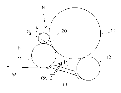
Referring to the accompanying drawings wherein the same reference numerals
refer to the
:>ame or similar elements, Fig. 1 shows a carrier-drum slitter-winder in which
a paper roll 10 is formed
~Nhile supported on the carrier drums 11 and 12. In an area 13 between the
carrier drums 11 and 12,
an air relief has been formed, e.g., by blowings from a blow device 13a,
wherein a pressure Pz is
f;ffective. The normal atmospheric pressure is denoted by reference P,. The
paper web W to be
'wound is passed through a winding nip N,defined between the first carrier
drum 11 and the paper roll
that is being formed, onto the paper roll 10. A wedge-shaped area 20 defined
after the carrier
drum I l and the paper roll 10 that is being formed (in the running or winding
direction of the web)
is sealed by sealing means or sealing members, for example a roll 14, and is
arranged to be subjected
to a positive pressure (i.e., an added or additional pressurization causing a
raised or higher pressure
level than previously existing), whereby a pressure P3 is effective in the
area 20. Roll 14 is arranged
proximate to the carrier drum 11 and the roll 10 being formed to enable it to
provide some sealing
Effect. In such a case, air cannot pass from the air relief area 13, along
with the paper web W, to
locations between the layers in the roll 10 that is formed because the
pressure chamber formed in the
area 20 substantially balances the difference between the relief pressure PZ
and the normal
atmospheric pressure P,.
In the exemplifying embodiment shown in Fig. 2, the paper web W is wound onto
a paper roll
10 in a carrier-drum slitter-winder, which includes the carrier drums 11 and
12. Between the carrier
drums 11 and 12, an air relief area 13 is provided, in which the pressure Pz
is effective. In the
environment, the normal atmospheric pressure P, is effective. Into the wedge-
shaped area 20 placed
;after the nip N defined between the first carrier drum 1 I and the paper roll
10 that is formed (in the
6
2191 OOl
running direction of the web), air is blown from air blow means 15a as a
directed air blowing 15,
whereby the wedge-shaped area 20 is pressurized, its pressure value being P3.
Thus, air is prevented
from being carned from the air relief area PZ along with the paper web W
between the material layers
on the paper roll 10 because the positive pressure P3 effective in the area 20
balances the difference
between the pressure P1 in the environment and the air relief pressure PZ.
In the exemplifying embodiment shown in Fig. 3, the paper web W is wound onto
a paper roll
in a Pope-type winder in which the paper web W is passed from a guide roll 9
over a winding
cylinder 11 into the winding nip N defined between the winding cylinder 11 and
the paper roll 10 that
is formed. From the winding nip, the web W is passed onto the paper roll 10.
Air is blown from air
10 blow means such as a blow device 16 as directed blowings 15 into the wedge-
shaped area 20 after
the winding nip N in the winding direction of the web, whereby the wedge-
shaped area 20 is
pressurized, and its pressure value is P3. Thus, from the area preceding the
winding nip N, air is
prevented from being carried along with the paper web W between the material
layers on the paper
roll 10 that is being formed, i.e., the transfer of air from the area before
the winding nip to the area
1 S after the winding nip is substantially reduced or retarded.
It should be recognized that the weight of the roll 10 being formed is
relieved by pressurizing
the area underneath the roll being formed before the winding nip N, e.g., by
the relief means 13a.
More particularly, in one embodiment, the roll 10 being formed is supported by
arranging the drums
or cylinders 11,12 spaced a distance from one another to define the air relief
area which encompasses
at least a part of a lower half of the roll 10 being formed. Thus, upon
pressurizing this area 13
between the drums 11,12, the weight of the roll 10 being formed is relieved.
The examples provided above are not meant to be exclusive. Many other
variations of the
7
present invention would be obvious to those skilled in the art, and are
contemplated to be within the
scope of the appended claims. For example, instead of the air relief blow box
13a, other air relief
pressure means may be used without deviating from the scope and spirit of the
invention.
8