Note: Descriptions are shown in the official language in which they were submitted.
CA 02191102 1999-10-26
-1-
COUNTERBALANCING MECHANISM FOR AN OVERHEAD DOOR
The present invention generally relates to overhead doors of the type
utilizing one or more counterbalancing torsion springs and, more particularly,
relates to the torsion spring counterbalancing mechanism generally associated
with such overhead doors as well as a winding mechanism for setting the
counterbalancing force of the spring.
Overhead doors generally require a counterbalancing force which enables
the door to be more easily moved between opened and closed positions either
manually or by way of a powered opening device. Often, overhead door systems
l0 rely on one or more torsion springs for providing this counterbalancing
force.
These
~cc~:mc~
WO 95/34733 PCTIUS95/07540
2191102
-2-
torsion springs must be wound during the installation of the garage
door assembly such that they are provided with the necessary preset
torque. Many systems require the installer to wind the spring
manually by using a rod to rotate the free end of the spring with
respect to a fixed end thereof and, after an appropriate number of
turns, rigidly securing the free end of the spring to the torsion shaft
of the overhead door assembly. This type of system is not only
difficult to install but is also quite dangerous to install and remove
due to the possibility of the installer inadvertently releasing the bar
and being injured as a result. Thus, installers must be quite
experienced to avoid the dangers involved with these prior systems.
Overhead door assemblies have been proposed in the
past which have addressed problems involving manual winding of
torsion springs. For example, certain gear systems have been
disclosed for winding the torsion spring. Such worm gear
arrangements are shown in U.S. Patent Nos. 3,921,761; 4,882,806
and 4,981,165. In each of these systems, a ring-shaped worm gear
is operatively coupled to the free end of the torsion spring and is
rotated by way of a mating worm drive gear or pinion which may be
driven either manually or with a power tool by the installer. Thus,
rotation of the ring-shaped worm gear also rotates or winds the
torsion spring to set the appropriate amount of torque in the spring.
These gear systems, however, each have disadvantages
which make them impractical to use in all but the most elaborate and
WO 95/34733 2191 10 2 PCTIUS95/07540
-3-
expensive overhead door assemblies. For example, these prior gear
systems require a number of precision machined parts and further
require very precise, and costly, assembly procedures. For example,
the worm drive gear in each is designed to rotate about an axis
perpendicular to the axis of the ring-shaped mating gear. Thus, the
gear teeth on each gear must be precisely machined and matched to
establish this perpendicular relationship. Additionally, the gear
systems shown in U.S Patent Nos. 3,921,761 and 4,882,806 are
designed such that the worm drive gear is oriented horizontally along
an axis perpendicular to the overhead door. This makes it difficult
for the installer to easily and safely apply a tool to the worm drive
gear during the winding process. The worm drive gear disclosed in
U.S. Patent No. 4,981,165 is also shown in a horizontal orientation
but also actually rotates with the torsion shaft and therefore this
system includes the further undesirable possibility of leaving the
worm drive gear in an even more inaccessible orientation. Also,
each of the worm gear systems described in the above patents
leaves open the possibility of undesirable rotation of the worm drive
gear and ring-shaped gear and a resulting unwinding action of the
torsion spring after the system has been wound. This may occur,
for example, the vibration caused during everyday operation of the
overhead door. Finally, none of these prior systems provide an easy
manner of identifying the number of turns that have been made in
the torsion spring. Further disadvantages of these systems will
WO 95/34733 2 ~ 9 2 ~ ~ ~ PCT/US95/07540
-4-
become more apparent upon review of the advantageous features of
the present invention.
Overhead door assemblies prior to the present invention
have also utilized torsion springs in which adjacent coils thereof abut
one another when the spring is in a normal, unwound resting state.
In other words, these springs have been manufactured in the past
such that there is no gap left between adjacent coils. Therefore,
during the initial winding process and during operation of the
overhead door, frictional force arising as the result of rubbing action
between adjacent coils of the shrinking spring must be overcome by
the system. This places the system under additional stresses and
strains which must be borne by the spring itself as well as the user
or the powered door opener, each of which is undesirable. The
additional stress and abrasion that the abutting coils cause on the
spring may lead to a shorter effective spring life and/or premature
failure of the spring.
Many prior systems not only use springs having
abutting coils but further fail to adequately provide for the growth
and contraction of the torsion spring during the operations of initially
winding the spring and of spring unwinding and winding during
raising and lowering of the door. Other systems that do provide
some means for accommodating spring growth and contraction tend
to be suitable for one operation but not the other or tend to be
complicated systems which are impractical in many applications,
WO 95/34733 2191 1 O ~ pCT/US95/07540
-5-
such as residential applications, and which create new problems
associated with their complicated design and installation procedures.
Still further disadvantages of existing systems involve
the high costs of manufacturing and stocking parts respectively
dedicated only to the left or right hand side of the overhead door
system as well as the complexity of installing systems such as those
disclosed in the patents mentioned above. Overall, past systems
have generally either been rather simple but difficult and dangerous
to install or perhaps easier to install but rather complex and
expensive.
A need in the art therefore exists for improvements
which, for example, allow easier installation of overhead door
systems as well as improved operation thereof while maintaining low
overall costs and a long useful life.
Summary of the Invention
To address various problems apparent in the art, the
present invention provides overhead door apparatus including a
counterbalancing mechanism constructed in accordance with various
embodiments as further described below. In a first embodiment of
this invention a manner of accommodating spring growth and
contraction in accordance with the present invention is through the
provision of a torsion spring with a preset gap between adjacent
coils of the spring when it is in its unwound, resting state. This gap
is calculated to substantially accommodate the added number of
21911Q2
WO 95/34733 PCT/US95/07540
-6-
coils which result from the initial winding process during installation.
The advantage of this method of accommodating spring growth
resides in its relatively low cost when compared to other methods.
Two alternatives to the above method of
accommodating spring growth are also provided. In each alternative
the counterbalancing apparatus includes a torsion shaft mounted for
rotation between first and second stationary supports and a torsion
spring having a first end operatively fixed to the torsion shaft such
that the first end rotates with the torsion shaft and moves axially
along the torsion shaft during raising and lowering of the overhead
door. The axially moving end of the spring accommodates spring
growth and contraction during any and all winding and unwinding
operations of the spring. The torsion spring. has a second end
operatively connected to a winding mechanism mounted to the first
support and functioning to wind the second end thereof with respect
to the first end while the door is held stationary in the down or
closed position.
A first alternative involves the use of a sliding spring
fitting or cone which includes a key slidably received by a keyway in
the torsion shaft. Preferably, the keyway comprises a pair of
deformed, elongate depressions in the torsion shaft and the key
comprises a complementary pair of protuberances within the sliding
cone. The second alternative adds roller elements to the fitting or
cone which are designed to reduce the friction and any possible
WO 95/34733 ~ ~ 191 10 2 pCT/US95/07540
_7_
binding between the fitting or cone and the torsion shaft. Each of
these alternatives allow the transfer of torque to occur between the
spring and the torsion shaft while accommodating the growth and
shrinkage of the spring in an axial direction.
In accordance with another aspect of the invention, a
winding mechanism is incorporated into the stationary support
structure at the second end of the spring. Two embodiments of the
winding mechanism are disclosed herein, however, each embodiment
allows the second end of the spring to be easily rotated or wound
with respect to the non-rotating first end thereof. Specifically, each
embodiment of the winding mechanism generally includes a ring-
shaped gear rotatably supported by the first stationary support and
operatively affixed to the second end of the torsion spring such that
rotation of the ring-shaped gear rotates the second end of said
spring with respect to the first end of said spring. A worm drive
gear is also rotatably supported by the first support and includes
outer threads or teeth that mesh with the teeth of the ring-shaped
gear. The worm is mounted in a "user friendly" orientation
extending at an angle generally between an approximately vertical
orientation and approximately a 45 ° orientation with respect to the
plane of the door for providing easy access by an installer standing
on the ground below the winding mechanism.
Each embodiment of the spring winding mechanism
utilizes a ring gear formed integrally with a spring cone or fitting on
WO 95/34733 ~ 1 9 i ~ Q 2
PCTIUS95/07540
_8_
which the second end of the spring is threaded. The ring gear and
spring cone structure of each embodiment is referred to herein as a
"gear cone". In the first embodiment, the ring gear is a spur gear
which provides an extremely cost effective and universal component
in the sense that it is neither right or left-hand dedicated, it also
allows for significantly more "play" or "forgiveness" during
installation than would conventional worm gear systems in which
components thereof are designed to be in nearly perfect alignment
with each other.
The first embodiment of the winding mechanism further
includes a gear retainer which engages the winding mechanism to
restrain the spur gear and worm drive gear from rotating during
normal operation of the door. However, the gear retainer is
disengageable from the gear system to allow operation of the gear
system during winding and unwinding of the torsion spring,
respectively, during installation and removal thereof. The gear
retainer automatically engages and disengages the worm drive gear
upon removal and application of an appropriate tool used to rotate
the worm drive gear. During normal operation of the door, the gear
retainer prevents so-called "creep" or undesirable rotation of the
worm drive gear, spur gear and any resulting unwinding of the
torsion spring from its pre-torqued, wound state.
In a further aspect of the first embodiment of the
winding mechanism, the various components associated therewith
WO 95134733 ?.191 i 0 2 pCT~TS95107540
_g_
are constructed and fixed in place such that the longitudinally
directed thrust load of the torsion spring is not directed onto the
sheet metal construction of the stationary support or mounting
structure. Rather, this thrust load is borne by the torsion shaft
which is placed under tension by the load and is much more able to
bear the load than is the sheet metal support structure.
The present invention also contemplates a second
embodiment which provides for a more "universal" construction of
various components associated with the winding mechanism. That
is, the gear housing and gears of the mechanism, as well as the
mounting bracket for the housing may be mounted on the right or
left side of the door while disposing the worm at a predetermined
easily accessible orientation. Also, a bearing unit is provided having
the same connecting elements as the gear housing such that full
interchangeability of the winding mechanism with a bearing unit is
provided when only one counterbalancing mechanism is necessary.
In the situation in which a relatively heavy overhead door requires
two counterbalancing mechanisms, the same winding mechanism
components are used on each side of the overhead door. Lower
manufacturing costs and other associated costs result as differently
designed left and right handed components do not have to be
separately manufactured and stocked.
The gear housing and the bearing units of the
"universal" second embodiment are each able to be interchangeably
WO 95/34733 PCT/I1S95/07540
X191 102
-10-
mounted to the same mounting bracket. The worm of the gear
housing is disposed at an accessible orientation and preferably at an
acute angle with respect to the plane of the door opening or the
same "user friendly" orientation as in the first embodiment. The
housing also acts as a bearing unit. Thus, when only one
counterbalancing mechanism is necessary, a winding mechanism is
fixed to a mounting bracket on one side of the torsion shaft and the
other end of the torsion shaft is supported for rotation in a bearing
unit fixed to a second mounting bracket. As the same mounting or
connecting elements are used on both the housing and the bearing
unit and the respective mounting brackets, when a bearing unit must
be substituted with a housing, or vice versa, it is simply a matter of
substituting one component for the other and attaching it in the
same manner. In addition, the mounting or installation operations of
the housing, the worm within the housing, and the bearing unit all
involve only snapping the respective components into place without
separate fasteners. These features, added to the ability to use the
same components on each end of the torsion shaft, creates a very
versatile system with relatively low overall costs.
As a further feature of the second embodiment, the
worm further includes tool engageable drive portions on respective
ends such that a worm drive portion is exposed away from the inside
of the door in a "user friendly" orientation no matter what side of the
door the gear housing is mounted on. In the second embodiment,
WO 95/34733 219 ~ i ~ 2 PCT/US95/07540
-11-
this orientation may be defined as one in which the worm extends at
an acute angle with respect to the plane of the overhead door
opening. Specifically, this orientation may be approximately 30°
relative to the door opening. This same orientation is obtained
whether the winding mechanism is mounted on the left or right hand
side of the door.
Also, the dual drive worm may be snapped into place in
either of two possible ways while ensuring that a drive portion is
exposed in the desirable "user friendly" orientation. When snapped
in place, a first drive portion is therefore exposed in the "user
friendly" orientation, however, the second drive portion is also
exposed outside of the housing such that it may be engaged by a
tool. This feature provides a back up driving location if the first
drive portion is damaged or if it is simply more convenient in a
particular application to drive the worm with the second drive
portion. Engagement of the worm with the helical ring gear portion
of the gear cone also assists in trapping the worm firmly into place
within the gear housing.
Finally, a winding counting device is provided in each
embodiment to indicate the number of turns made in the torsion
spring during the installation procedure. This is especially desirable
when a direct view of the torsion spring is prevented by a cover
provided for aesthetic purposes. In the first embodiment, the
counting device comprises a toothed wheel which engages the ring
WO 95/34733 ( PCT/US95/07540
-12-
gear and traverses along a scale indicating the number of spring
windings. In the second embodiment, the counting device comprises
a clip which attaches to a threaded portion of the gear cone located
between the cone portion and the gear portion thereof. The clip has
a pointer extending outwardly through a slot in the housing and
indicating the number of windings on a scale provided on the
housing.
These and other advantages of the present invention
will become more readily apparent upon review of the following
detailed description of the preferred embodiments thereof taken in
conjunction with the accompanying drawings.
Brief Description of the Drawin4s
Fig. 1 is a diagrammatic perspective of an overhead
door assembly with the door in a lowered, closed position and
incorporating a first preferred embodiment of the counterbalancing
mechanism of the present invention;
Fig. 2 is a cross sectional view of the counterbalancing
mechanism taken along line 2-2 of Fig. 1 but shown with the torsion
spring thereof in the unwound state thereof corresponding to a
raised, opened door;
Fig. 3 is a partially fragmented view of the torsion
spring winding mechanism of the first embodiment taken generally
along line 3-3 of Fig. 2;
Fig. 3A is a cross-sectional view of the torsion spring
WO 95/34733 PCT/US95/07540
-13-
winding mechanism taken along line 3A-3A of Fig. 3 to show details
of the device for counting the number of spring windings;
Fig. 4 is a cross sectional view of the torsion spring
winding mechanism taken generally along line 4-4 of Fig. 3;
Fig. 5 is a perspective view of an alternative
embodiment of the spring end fitting and torsion shaft of the
counterbalancing mechanism;
Fig. 6 is a cross sectional view in side elevation of a
third alternative of the spring end fitting and torsion shaft of the
counterbalancing mechanism;
Fig. 7 is a cross sectional view taken along line 7-7 of
Fig. 6;
Fig. 8 is a diagrammatic perspective of an overhead
door assembly with the door in a lowered, closed position and
incorporating a second embodiment of the counterbalancing
mechanism of the present invention;
Fig. 9 is a fragmented perspective view of the winding
mechanism on the left hand side of overhead door assembly as
shown in Fig. 8;
Fig. 10 is a front elevational view of the mounting
bracket used for the winding and counterbalancing mechanisms of
Fig. 9;
Fig. 11 is a partially fragmented and exploded view of
the spring winding mechanism with the housing and gear cone in
2a ~? 1 C2
WO 95/34733 PCT/US95/07540
-14-
cross section to illustrate the mounting and engagement of the gear
cone therein;
Fig. 12 is an end view of the spring winding mechanism
shown in Fig. 11 but with the housing and gear assembly fully
assembled within the housing and the housing rotated 60° to show
a preferred orientation of the worm in use;
Fig. 13 is a perspective view of a bearing unit mounted
in place of the counterbalancing mechanism and associated winding
mechanism shown on the right hand side of Fig. 8;
Fig. 14 is a side elevational view of the bearing unit
shown in Fig. 13;
Fig. 15 is a side elevational view of the spring winding
mechanism of the second embodiment fragmented to show the
spring winding counting device; and,
Fig. 16 is a side elevational view of the clip used in the
spring winding counting device of Fig. 15.
Detailed Description of the Preferred Embodiments
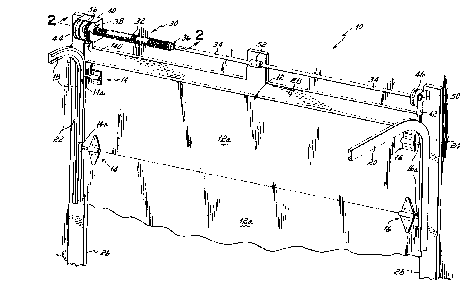
Referring first to Fig. 1, a first embodiment of the
present invention generally comprises an overhead door system 10,
such as a residential garage door or a commercial overhead door
system, including a door 12 which may be conventionally made up
of a plurality of horizontal, hinged panels 12a. Panels 12a each have
roller assemblies 14, 16 affixed at opposite ends thereof, at least
some of which are associated with the door panel hinges, for
WO 95/34733 PCT/US95/07540
-15-
example, and which include rollers 14a, 16a riding in a pair of curved
tracks 18, 20 as is conventional in the art. Tracks 18, 20 are rigidly
affixed to side frame members 22, 24 which, in part, define a door
opening 26. As is conventional, tracks 18, 20 may also be
supported from structure (not shown) disposed above frame
members 22, 24. Door opening 26 is further defined by upper frame
structure 28.
As further shown in Fig. 1, door 12 may be raised and
lowered to respectively expose and close door opening 26 and, to
assist in such raising and lowering operations, a counterbalancing
mechanism 30 is used and constructed in accordance with the
present invention. Counterbalancing mechanism 30 generally
includes a torsion spring 32 which has a first end operatively
connected to a torsion shaft 34 by being threaded onto an inner
spring fitting or cone 36 in a conventional manner. Cone 36 is
rigidly affixed to torsion shaft 34 by a plurality of set screws 35, one
of which is shown in Fig. 2. Torsion spring is operatively connected
to a winding mechanism 38 at a second end thereof. The winding
mechanism 38 is supported by a first fixed support 40 which
comprises a housing constructed of sheet metal and rigidly fastened,
as with bolts (not shown), to the frame structure 22 adjacent to
door opening 26. A second fixed support 42 is located at the
opposite end of torsion shaft 34 and is likewise constructed of sheet
metal and rigidly fastened to the frame structure 24 adjacent to door
WO 95/34733 2 l 9~ ~ ~ ~ ~ PCT/US95/07540
-16-
opening 26. Torsion shaft 34 is supported for rotation between
fixed supports 40, 42 and further includes drums 44, 46 rigidly
affixed, as with set screws (not shown), to torsion shaft 34 for
rotation therewith in a conventional manner. Cables extend from
drums 44, 46 and are connected to the bottom of the overhead door
12 in a conventional manner. Torsion shaft 34 is connected to fixed
support 40 by way of a roller bearing 48 (Fig. 2), as further
discussed below, and to fixed support 42 by way of a second roller
bearing 50. Bearings 48, 50 allow rotation of torsion shaft 34
during operation, i.e., raising and lowering, of door 7 2. Torsion
shaft 34 has a two-piece construction with the pieces being
connected to each other at a central location by a coupling 52.
Referring now to Figs. 2-4, winding mechanism 38
includes a gear cone 54 which incorporates a ring-shaped gear 56
thereon as well a cone portion 58 and a hub portion 60. Gear 56,
cone portion 58 and hub portion 60 are integrally formed with one
another, preferably by being die cast as a single unit from aluminum.
Ring shaped gear 56 is preferably a spur gear, that is, gear 56
includes straight, peripheral teeth 62 which are both parallel to one
another and parallel to the axis of rotation of gear 56. This aspect
of the invention is the feature that allows the entire gear cone 54,
including gear 56 incorporated therein, to be die cast in a single
molding operation. The use of a spur gear 56 also causes the gear
cone 54 to be "universal" in the sense that it may be used on either
WO 95/34733 PCT/US95/07540
_17_ 2191102
end of torsion shaft 34.
As best shown in Fig. 3, gear cone 54 is mounted for
rotation within housing 40 and about torsion shaft 34. In this
regard, a cylindrical Nylon bushing 64 is press fit within gear cone
54. Torsion shaft 34 rotates with respect to gear cone 54 and its
inner bushing 64. Specifically, and as further discussed below, gear
cone 54 and bushing 64 rotate about torsion shaft 34 during the
initial winding of torsion spring 32 and torsion shaft 34 rotates
within gear cone 56 and bushing 64 during raising and lowering
operations of door 12. As further shown in Fig. 3, gear cone 56 is
received by a slot 66 in housing 40 but remains spaced from an
inner end 68 of slot 66 such that housing 40 does not prevent free
rotation thereof during a winding operation.
Winding mechanism 38 further includes a worm drive
gear 70 mounted for rotation within housing 40 between brackets
72, 74. Worm drive gear 70 includes outer, helical teeth or threads
76 which mesh with teeth 62 of spur gear 56. Rotation of worm
drive gear 70 in one of the two possible directions will therefor
rotate gear cone 54 in a corresponding direction to either wind or
unwind torsion spring 32. To facilitate rotation of worm drive gear
70, a driving head 78, engageable by a suitable tool, is provided on
an exposed end thereof. In the preferred embodiment, driving head
78 includes a hex portion 78a which may be engaged by a socket
tool 80 (Fig. 3) and rotated either manually or in a power assisted
WO 95/34733 2191 10 ~ PCT/US95/07540
-18-
manner such as by being pneumatically driven.
In accordance with another aspect of this invention, a
gear retainer 82 is provided for preventing rotation of worm drive
gear 70 and gear cone 54 when hex portion 78a is not engaged by
tool 80 but for allowing rotation thereof when hex portion 78a is
engaged by tool 80. Specifically, gear retainer 82 comprises a
resilient spring clip 84 which is rigidly secured to housing 40 and
includes an angled portion 86 which normally engages the hex
portion 78a of head 78 in the clip's unbiased state, shown in solid in
Fig. 3. As best illustrated in Figs. 2 and 4, portion 86 of clip 84
includes an aperture 88 through which hex portion 78a of head 78
extends. Aperture 88 has at least two straight edges 90, 92 that
engage hex portion 78a of head 78 to normally prevent or restrain
any rotation of worm drive gear 70 and therefore of gear cone 54
during normal operation of door 12. During winding and unwinding
of the spring with the door maintained stationary, however, tool 80
is pushed onto hex portion 78a of head 78 and this pushes portion
86 of clip 84 to the position shown in phantom in Fig. 3 such that
aperture 88 and, more specifically, edges 90, 92 are in alignment
with a stepped down or recessed portion 94 of head 78. When
aperture 88 is aligned about stepped down or recessed portion 94,
hex portion 78a of head 78 is free to rotate and worm drive gear 70
may therefore also be rotated to either wind or unwind spring 32.
As illustrated in Fig. 3, worm drive gear 70 extends
WO 95/34733 PCTNS95/07540
-19-
along an axis 95 which is ideally fixed at approximately 45° to
horizontal and extends into the plane of door opening 26 (Fig. 1
with the drive head 78 directed downwardly and inwardly into the
interior of, for example, the garage. More generally, for easy access
by an installer standing on the ground below winding mechanism 38,
worm drive gear 70 is preferably oriented between an approximately
vertical orientation and approximately the 45 ° position shown in Fig.
3. As further shown in Fig. 4, the axis 95 of worm drive gear 70 is
also oriented at a slight angle a with respect to a plane 97 which is
perpendicular to door opening 26 and to the axis of rotation of spur
gear 56. Angle a substantially corresponds to the lead angle of the
teeth or threads 76 of worm drive gear 70 and may, for example, be
approximately 4°. Angle a results from the angled teeth or threads
76 meshing with the straight, parallel teeth 62 of spur gear 56
which extend parallel to the axis of rotation of spur gear 56. This
aspect of the invention allows even easier access to the head 78 of
worm drive gear 70 by the installer since the head 78 of worm drive
gear 70 is not only angled downwardly toward the installer, but also
inwardly toward the center of door opening 26.
Referring again to Fig. 2, housing 40 further includes a
bearing plate 96 into which bearing 48 is press fit. Inner race 98 of
bearing 48 receives and rotates with torsion shaft 34 and with
respect to outer race 100 which remains stationary. Inner race
bears against bushing 64 (Fig. 3) on one side and against hub 102 of
WO 95/34733 PCT/US95/07540
-20-
drum 44 on the other side. Therefore, as drum 44 and its hub 102
are rigidly affixed to torsion shaft 34 at one end of counter balancing
mechanism 30 and inner spring fitting or cone 36 is affixed to
torsion shaft 34 at the opposite end, there is no thrust load or, in
other words, there is virtually no longitudinally directed force on the
sheet metal housing 40 and bearing plate 96. In this regard, torsion
shaft 34 bears virtually all of this thrust load since, by design, it is
placed under tension between the two rigid, e.g., set screw,
connections respectively made between torsion shaft 34 and drum
44 ~at one end and between torsion shaft 34 and fitting 36 at the
other end. For this reason, the longitudinally directed stresses are
experienced by torsion shaft 34 rather than by housing 40 and
bearing plate 96 which are made of sheet metal much less able to
handle such stress over time than the tubular torsion shaft 34. Also,
due to this design bearing 48 does not need to be a relatively
expensive thrust bearing but need only be a simpler, less expensive
roller bearing.
In another aspect of the first embodiment of this
invention, torsion spring 32 is formed with a specifically determined
gap 104 formed between adjacent coils 106 when the spring 32 is
in a resting or unwound state. Gaps 104 allow additional coils 106
to be added to the spring during the initial winding process and
during the winding that occurs while lowering door 12. Since
adjacent coils 106 do not touch as spring 32 is wound and as
CA 02191102 1999-10-26
-21-
additional coils are added, there is no need to overcome the additional
frictional
forces encountered with conventional springs having abutting coils. It has
been
found that the specific gap must be formed precisely in order to retain the
necessary rigidity and performance of the spring across many varied
applications.
In accordance with the present invention, the size of each gap 104 between
adjacent coils 106 is generally determined by the following formula:
Gap = ~d)x(~N)x(fo~
N
where: d - diameter of coil spring wire
1o ON = number of coils added during winding
fo - overtravel factor
N - total number of coils of unwound spring
For a residential application, a typical spring wire diameter (d) may be 6.4
mm ('/d") and a typical number of coils added during winding (~N) may be
approximately 10 while a typical total number of coils (N) may be about 100.
Ideally, gaps 104, each being the same width, would be calculated such that at
the end of an initial winding operation to set the required torque in the
spring 32,
adjacent coils 106 would just abut one another. However, an overtravel factor
fo
has been included in the above formula to allow for some overwinding of the
spring during installation of the counterbalancing mechanism 30. The
overtravel
factor will be approximately in the range of 1.1-2.0 and is preferably about
1.25.
This factor results in a gap that is somewhat greater than ideal but that is
desirable to allow for an installer to "over-wind" the spring to some extent
without
causing adjacent coils 106 to rub against one another as a result of such over-
winding. Therefore, as one example, a residential torsion spring might have
gaps
104 between adjacent coils 106 calculated as follows:
I~d:md
CA 02191102 1999-10-26
-22-
Gap = (.25)x(10~x(1.25) = 0.03125" = 1/32" or 0.79 mm
100
These gaps will vary from application to application, however, using the above
formula of the present invention, an appropriate gap 104 may be calculated for
each application such that the coils added during winding are accommodated
while maintaining the structural integrity and performance of the spring. For
many
applications, especially residential applications, the gap will be between
about
0.40 and 0.79 mm ( 1 /64" and 1 /32")
Another manner of accommodating spring growth and contraction
l0 according to the present invention is illustrated in Fig. 5. This figure
only shows
the spring end fitting or cone of the counter-balancing mechanism as welt as a
portion of the torsion shaft thereof. The remaining portions of the
counterbalancing mechanism are preferably identical to those of
counterbalancing
mechanism 30 shown in Figs. 1-4. According to this embodiment of the
invention,
the torsion shaft 110 is shaped with two, diametrically opposite elongate
depressions 112, 114 which extend along the length of the tubular shaft 110.
Torsion shaft 110 receives a spring end fitting or cone 116 in a manner which
allows end fitting or cone 116 to move
~d:md
WO 95/34733 ~ 4 PCT/US95/07540
-23-
axially or slide along torsion shaft 110 but not to rotate about
torsion shaft 110. Specifically, end fitting or cone 116 includes two
oppositely directed protuberances 117, 119 which complement the
depressions 112, 1 14 and mate therewith in a manner similar to key
and keyway connections.
An outer end of spring 118 is fixed to a stationary
support, such as to the winding mechanism 38 and housing 40 as
shown in Figs. 1-3 while the inner end of spring 118 is threaded
onto cone 116 in a conventional manner. Cone 116 is free to slide
along torsion shaft 110 to accommodate growth and contraction of
spring 118 during initial winding thereof as well as during raising and
lowering of the overhead door. Significantly, end fitting or cone 116
is not fixed to shaft 110 with a set screw as is conventional but
does rotate therewith because of the unique key/keyway type
connection. A conventional spring having abutting coils in its
unwound state may be utilized in this embodiment as the use of a
sliding end cone accommodates the coils added during winding
processes.
Figs. 6 and 7 illustrate a still further embodiment of an
axially movable inner fitting or end cone which is identical in purpose
and design to the fitting or cone 116 shown in Fig. 5 except that
means are provided for reducing sliding friction between the end
cone and the torsion shaft. More particularly, a torsion shaft 120
mounts a sleeve having two, oppositely facing elongate recesses or
WO 95/34733 PCT/US95/07540
-24-
grooves 122, 124 which extend an appropriate length along shaft
120 to accommodate growth and contraction of spring 136. The
sleeve 121 of torsion shaft 120 receives a spring end fitting or roller
cone 126 in a manner which allows end fitting or roller cone 126 to
roll axially along torsion shaft 120 but not to rotate about torsion
shaft 120. Specifically, end fitting or roller cone 126 includes
friction reducing rolling elements preferably taking the form of two
rollers 128, 130 which register within and roll along the respective
recesses 122, 124. Rollers 128, 130 are fixed within roller cone
126 by respective pins 132, 134 about which rollers 128, 130
rotate.
An outer end of spring 136 is fixed to a stationary
support, such as to the winding mechanism 38 and housing 40 as
shown in Figs. 1-3 while the inner end of spring 136 is threaded
onto cone 126 in a conventional manner. Cone 126 rolls along the
sleeve 121 of torsion shaft 120 to accommodate growth and
contraction of spring 136 during initial winding thereof as well as
during raising and lowering of the overhead door.
As mentioned above, the embodiment of Figs. 6 and 7
is aimed at reducing the friction between the end cone and torsion
shaft. Such undesirable friction might be present in the sliding cone
116 and torsion shaft 110 constructed in accordance with Fig. 5. It
is also contemplated, however, that an anti-friction surface or
coating may be used in the embodiment of Fig. 5 between the two
WO 95/34733 ~ PCT/US95107540
-25-
relatively sliding components. This might comprise a coating of
lubricated plastic or other anti-friction material on the outside surface
of torsion shaft 1 10 or an insert of lubricated plastic or other anti-
friction material within cone 116.
Returning now to Fig. 3 taken along with Fig. 3A, a
counting mechanism 140 is provided with winding mechanism 38 in
order to allow an installer to readily identify the number of turns
being given to torsion spring 32 by way of tool 80 during installation
of system 10. Counting mechanism 140 includes a counter gear
142 having a plurality of gear teeth 144 that extend through a
window 158 in housing 40 and mesh with gear teeth 62 of gear 56.
Counting gear 142 further includes a central, internally threaded hub
146 that receives an externally threaded, fixed rod 148. Threaded
rod 148 is rigidly fixed at opposite ends thereof to a counting
mechanism housing 150. Thus, as gear 56 is rotated by worm drive
gear 70, counter gear 142 will rotate and, at the same time,
translate along fixed threaded rod 148. Graduations 152 are
provided on the outside of housing 150 to give a visual indication to
the installer of the number of turns or winds. A pointer 154 is
connected to the outside of hub 146 such that relative rotation is
allowed between counting gear 142 and pointer 154 and gear 142.
Pointer 154 has an end portion 154a that protrudes from a slot 156
in housing 150. End portion 154a points to a particular graduation
or number 152 on the outside of housing 150 to indicate the number
WO 95/34733 ~ ~ 91 10 ~ PCT/US95/07540
-26-
of turns in spring 32. It wilt be appreciated that other indicators may
be provided instead of pointer 154 and graduations 152. For
example, a counter wheel having numbers for indicating the number
of turns might be substituted into counting mechanism 140 by one
of ordinary skill.
In the preferred embodiment, counting gear 142 will
have nine teeth while gear 56 will have forty-five teeth thus creating
a ratio of 5:1. Every five turns of counter gear 142, end portion
154a of pointer 154 will point to another graduation thus indicating
another turn of gear 56 and spring 32. Typically, torsion springs
such as spring 32 will require approximately seven to eight turns. It
will be appreciated that other gear ratios may be chosen in
conjunction with various thread pitches of rod 148. In all cases, the
translation of counter gear 142 will never be greater than the width
of gear 56.
Referring now to Fig. 8, a second embodiment of the
present invention generally comprises an overhead door system 200
which may be identical to the first embodiment in that a
conventional sectional door 202 is provided and supported for
movement on tracks 204, 206 by rollers (not shown). Tracks 204,
206 are rigidly affixed to side frame members 208, 210 and by
upper metal frames 212, 214. The door opening is defined by side
frame members 208, 210 as well as upper frame structure 216. In
accordance with this second embodiment, universal
WO 95/34733 2191 10 ~ pCT/US95/07540
-27-
counterbalancing mechanisms 218, 220 are provided for assisting
with the opening and closing operations of door 202. Two such
counterbalancing mechanisms 218, 220 are shown in Fig. 8,
however, only one of the mechanisms 218, 220 may be necessary
depending on factors such as the spring force provided and the
weight of door 202.
Still referring to Fig. 8, counterbalancing mechanisms
218, 220 are each generally constructed with components similar in
function to the first embodiment. In this regard, the description of
torsion springs 222, 224 given with respect to the first embodiment
above may be referred to here as well and any of the alternatives for
accommodating spring growth may be used in the second
embodiment as well. The significant differences between the
counterbalancing mechanism 30 of the first embodiment and
counterbalancing mechanisms 218, 220 of the second embodiment
concern the various components which comprise the universal
winding mechanisms 226, 228. These mechanisms 226, 228 are
referred to as being "universal" in the sense that the same
components may be mounted on the left hand side of door 202, as
is mechanism 226, or on the right hand side of door 202, as is
mechanism 228. In each location, the respective worms 230, 232
are disposed in a "user friendly" orientation extending at an acute
angle relative to the plane of the door opening between frames 208,
210, 216. For purposes of simplicity, the plane of the door opening
WO 95/34733 2 l 91 1 ~ 2 PCT/US95/07540
-28-
may be considered as the same as a plane containing surfaces 208a,
210a, 216a of frames 208, 210, 216. As will be appreciated from
the description below, the angular disposition of worm 230 is
specifically shown to be 30° relative to the plane of the door
opening.
Winding mechanisms 226, 228 are supported by
respective fixed stationary supports or mounting brackets 234, 236
which mount gear housings 238, 240 constructed in accordance
with this second embodiment. A torsion shaft 242 is supported for
rotation between mounting plates 234, 236 and a pair of drums
244, 246 are rigidly affixed, as with set screws (not shown), to
torsion shaft 242 for rotation therewith in a conventional manner.
Cables 248, 250 extend from drums 244, 246 and are connected to
the bottom of the overhead door 202 also in a conventional manner.
When two counterbalancing mechanisms 218, 220 and
their associated gear housings 238, 240 are used as shown in Fig.
8, gear housings 238, 240 provide bearings for torsion shaft 242 in
the manner discussed below. Preferably, housings 238, 240 are
formed from injection molded Nylon having approximately 50% fiber
glass/ceramic filler to provide. The specific preferred material is
"Esbrid" No. NSG 240A which may be obtained from Thermofil, Inc.,
located in Brighton, Michigan. All of the major components of
winding mechanisms 226, 228 are preferably formed from this
plastic material. Torsion shaft 242 and springs 222, 224 are
WO 95/34733 2191 10 2 pCT~S95/07540
-29-
completely enclosed by a cover 252 which is comprised of two
telescoping sections 254, 256. Cover 252 provides protection in
the event that spring 222 or 224 breaks, while the telescoping
nature thereof allows one section 254 or 256 to be easily moved
toward the other to expose spring 222 or 224 during installation,
maintenance or inspection procedures. The outer end of each
section 254, 256 is connected to winding mechanisms 226, 228
and specifically to the housings 238 of each. In this regard,
referring briefly to Fig. 1 1, two stepped portions 255, 257 are
provided on housing 238 such that housing 238 may frictionally
receive either smaller diameter section 254 or larger diameter section
256 depending on which side of door 202 housing 238 is mounted.
Fig. 9 illustrates the left hand side counterbalancing
mechanism 218 from which the identical components forming
mechanism 220 will be fully understood. Inner end 258 of torsion
spring 222 is threaded onto a cone portion 260 which is rotatable
relative to torsion shaft 242 and will be discussed further below.
Referring briefly to Fig. 8 inner ends of each spring 222, 224 also
include respective fittings or "cones" 261, 265 for attaching springs
222, 224 to torsion shaft 242. These cones 261, 265 may be
axially movable as in the first embodiment or spring 222 may be
have gaps between adjacent coils as in the first embodiment to
accommodate spring contraction and growth during winding.
Worm 230, which is used to effect winding of spring
WO 95/34733 PCT/US95/07540
-30-
222 in the same manner as described above with respect to the first
embodiment, includes drive portions 262, 263 (Fig. 12) at each end
each comprising an external hex drive and each further including an
internal hex drive, although only one internal hex drive 264 is shown
in the drawings. Thus, worm 230 may be engaged by different
types of tools at both ends. One of the ends 262 will be exposed at
a user friendly orientation at approximately a 30 degree angle
measured up from the plane of the door opening, which plane may
be defined as the plane of plate section 283 of bracket 234 for
simplicity when viewing Fig. 9. More generally, this angle is at least
an acute angle measured up from the plane of the door and
preferably between vertical and approximately 45 ° with respect
thereto. As will be described below, a pointer 266 indicates the
number of spring windings on a scale 268 as pointer 266 projects
through and traverses along a slot 269 contained in housing 238.
Turning now to Fig. 10-12, mounting bracket 234 and
housing 238 are uniquely designed to allow housing 238 to be
connected to mounting bracket 234 in an easy snap-in operation and
without the use of additional fasteners. Specifically, as shown in
Fig. 10, mounting bracket 234 is provided with a slot 270 which
receives a cylindrical mounting portion 272 (Fig. 11 ) of housing 238
with a close sliding fit. Slot 270 includes an open end 273 and a
closed curved end 274 having a radius of curvature equal to the
radius of cylindrical mounting portion 272 (Fig. 11 ) of housing 238.
WO 95/34733 ~ PCTIUS95107540
-31-
Two opposed projections or inward "bumps" 276, 278 are formed at
each end of curve 274. Curve 274 forms slightly more than a semi-
circular curve between these two projections 276, 278 such that
cylindrical mounting portion 272 (Fig. 11 ) is firmly held in place for
rotation in closed end 274 by projections 276, 278 after cylindrical
mounting portion has been "snapped" past projections 276, 278.
As shown best in Fig. 10, mounting bracket 234 further
includes two flange mounts 280, 282 which receive oppositely
extending flanges 284, 285 (Fig. 12? of housing 238 as housing 238
is slid into slot 270 and snapped in place between projections 276,
278. Mounting bracket 234 is generally "L"-shaped in cross section
and includes one plate section having flange mounts 280, 282 and
one perpendicular section 283 including mounting holes 286, 288
for mounting bracket 234 to surface 208a of frame member 208
(Fig.8).
An overall understanding of the construction of winding
mechanism will be best understood from Figs. 11 and 12. A circular
flange 290 is provided adjacent to cylindrical mounting portion 272
for holding housing 238 in the position shown in Fig. 9 with bracket
234 disposed between flanges 284, 285 and flange 290. Flanges
284, 285 extend away from housing 238 in directions parallel to the
axis of worm 230 which is disposed therebetween. A central hole
292 is formed for closely receiving torsion shaft 242 (Fig. 9) for
rotation therein. Specifically, a cylindrical inner bearing surface 294
WO 95/34733 ~ PCT/US95/07540
-32-
is provided for torsion shaft 242 (Fig. 9) by a cylinder 296 molded
into housing 238. As further shown in Fig. 11, an integral gear cone
298 is mounted for rotation within housing 238. Gear cone 298 is
integrally formed with a cone portion 260, a threaded portion 302
and a helical gear portion 304. An inner cylinder 306 is molded into
gear cone 298 and is received for rotation on cylinder 296 within
housing 238 by simply sliding gear cone 298 completely into open
end 307 of housing 238. For reasons discussed below, an annular
retaining slot is provided between threaded portion 302 and helical
gear portion 304 of gear cone 298. As best shown in Fig. 12, in
addition to slot 269 previously mentioned, another slot 310 is
provided on the opposite side of housing 238 such that housing 238
may be used on either the left or right hand side of overhead door
system 200 (Fig. 8) and a slot 269 or 310 will be facing inwardly for
easy visibility to the installer.
As further shown in Figs. 11 and 12, worm 230 is
mounted for rotation within a worm housing portion 312 of gear
housing 238 such that worm 230 is engaged with helical gear
portion 304. Worm housing 312 includes a pair of end slots 314,
316 (Fig. 12) having closed curved ends 318 (only one of which
appears in the drawings) which receive respective cylindrical shafts
320, 322 of worm 230 for rotation. Respective pairs of inward
projections or curved "bumps" 323, 324 and 325, 326 keep shaft
portions 320, 322 within the closed curved portions of slots 314,
WO 95/34733
2191 1 ~ 2 pCT~S95/07540
-33-
316 after shaft portions 314, 316 have been "snapped" in place
past projections 323, 324 and 325, 326. The connection is
exemplified in Fig. 11 with cylindrical shaft 320 retained for rotation
within closed curved slot end 318. It will be understood that the
opposite shaft 322 is retained in slot 316 in exactly the same
manner and therefore the description of slot 314 applies to slot 316
as well.
Referring specifically to Fig. 1 1, curved end 318 has a
radius of curvature substantially equal to the radius of cylindrical
shaft 320. Curved end 318 forms slightly more than a semi-circular
curve between projections 323, 324 such that cylindrical shaft 320
is firmly held in place for rotation in closed end 318 by projections
323, 324. To help ensure that worm 230 is retained firmly in worm
housing 312, ratchet teeth 327, 328 are provided on opposing sides
of slot 314 for engaging ratchet teeth 329, 330 of a retainer piece
331. Retainer piece 331 closes both slots 314, 316, although only
one end of retainer piece 331 for slot 314 is shown. The end of
retainer piece 331 which closes slot 316 is of the same design.
Retainer piece 331 includes a curved surface 332 for engaging or at
least following the outer surface of cylindrical shaft 320 of worm
230. Retainer piece 331 is simply pushed into slot 314 once worm
230 has been inserted into housing 312 as shown in dotted lines in
Fig. 11. Ratchet teeth 327, 328 engage respective ratchet teeth
329, 330 to prevent retainer piece 331, and therefore worm 230,
WO 95/34733 2191 10 2 PCT/US95/07540
-34-
from coming loose or coming completely out of housing 312. It will
be appreciated that the main retention for worm 230 within housing
312 is provided by helical ring gear portion 304 of gear cone 298
since the teeth of gear portion 304 trap worm 230 within housing
312 preventing withdrawal out slots 314, 316.
When only one counterbalancing mechanism, such as
mechanism 218 in Fig. 8, is necessary for a particular overhead
door, then the other counterbalancing mechanism 220 is substituted
with a bearing unit 336 as shown in Figs. 13 and 14. Bearing unit
336 simply substitutes for the entire counterbalancing mechanism
220 by attaching in exactly the same manner to mounting bracket
236. In this regard, bearing unit 336 is inserted into slot 338 of
bracket 236 in exactly the same manner as described above with
respect to mounting bracket 234 and housing 238. Slot 338 has
the same configuration as slot 270 in mounting plate 234. Flange
mounts 340 (only one being shown in Fig. 13) are provided for
receiving a pair of flanges 342, 344 (Fig. 14) extending from bearing
unit 336. An inner bearing portion 346 receives torsion shaft 242
and allows free rotation thereof as door 202 (Fig. 8) is opened and
closed. It will further be appreciated that bearing unit 336 has an
identically designed cylindrical mounting portion 348 and circular
flange 350 as housings 238, 240 to facilitate complete
interchangeability of bearing unit 336 with either housing 238 or
240. Outer periphery 336a of bearing unit 336 is sized to receive
PCT/US95/07540
WO 95/34733
-35-
one of the ends of cover 252 (Fig. 8) with a friction fit. Stepped
portions are not illustrated on bearing unit 336 as they are on
housing 238, as bearing unit 336 may always be mounted on the
same side of door 202 when only one counterbalancing mechanism
220 is necessary. Of course, stepped portions could be provided if
desired.
As briefly mentioned above, each winding mechanism
226, 228 is provided with an identical mechanism for counting the
number of windings imparted to the respective torsion springs 222,
224. Therefore, the description of counting device.266 of winding
mechanism 226 will suffice for purposes of clarity. As shown in
Figs. 15 and 16, the counting mechanism of the second embodiment
utilizes a clip 352 which clips onto threaded intermediate portion
302 of gear cone 298 and includes an inwardly extending thread
354 of the same pitch as threaded portion 302. Clip 352 further
includes a central pointer 356 which extends through and is
captured with slot 269. Pointer 356 indicates the number of spring
windings by pointing to corresponding graduations on scale 268. As
pointer 356 is captured within slot 269, it does not rotate with
threaded portion 302, but instead traverses along slot 269 as gear
cone 298 rotates. The pitch of threaded portion 302 and the
spacing of graduations on scale 268 are chosen such that one full
turn of helical gear portion 304 and therefore spring 222 (Figs. 8 and
91 will be indicated as one winding or turn on scale 268.
WO 95/34733 219 ) i ~ 2 PCT/US95/07540
-3 6-
It will be appreciated from Fig. 16 that clip ends 358,
360 are able to grip threaded portion 302 because clip 352 forms
more than a semi-circle, however, clip 352 is still dimensioned with
a small enough curvature and is also resilient enough to be easily
clipped onto threaded portion 302 of gear cone 298. Like the other
major components of winding mechanism 226 and bearing unit 336,
clip 352 is preferably formed from the "Esbrid" nylon mentioned
above.
Finally, as also shown in Fig. 15, a gear cone retaining
plate 362 is fixed to gear housing 238, and specifically to a mount
364 having a threaded hole 364a (Figs. 1 1 and 12) thereof, by a
screw fastener 366. Retaining plate 362 extends into annular slot
308 located between threaded portion 302 and helical gear portion
304 of gear cone 298. This retaining plate 362 ensures that gear
cone 298 is retained within housing 238 during shipping and
handling of the assembly prior to assembly and may also be left in
place after installation to help stabilize gear cone 298 within housing
238 and ensure more accurate counting of the spring windings.
Operation
Referring to Fig. 1, after the garage door 12 and
counterbalancing mechanism 30 have been installed substantially as
shown in Fig. 1 with the door 12 in a closed position, the installer
simply engages drive head 78 of worm drive gear 70 with an
. appropriate tool 80 (Fig. 3) to disengage gear retainer 82 and then
WO 95/34733 ~ PCT/US95/07540
-37-
rotates worm drive gear 70 clockwise as viewed from the
perspective of Fig. 2. This rotates gear cone 54 and winds spring
32, adding a number of coils equal to the number of turns of gear
cone 54. When end portion 154a of pointer 154 reaches the
required number of turns as indicated on the graduated scale 152,
the installer stops turning worm drive gear 70. When tool 80 is
disengaged, gear retainer and, more specifically spring clip portion
86 automatically springs back to restrain hex portion 78a of drive
head 78 from rotating.
It should be noted that if adjacent coils were abutting
or, in other words, touching when the winding process was started,
then the spring would grow or lengthen by an amount corresponding
to the number of coils added. However, with the present invention,
this spring growth is accommodated through the use of the spring
32 having the preset gap 104 between adjacent coils 106 or by one
of the two moving end fittings or cones 116 or 126 which replace
fitting 36 when a spring having abutting coils is used. Spring
growth and contraction is also accommodated during normal raising
and lowering operations of door 12 by way of either the
predetermined gaps 104 of spring 32 or by way of an axially moving
end fitting or cone 116 or 126 as described above. Unwinding of
the spring is accomplished in the same manner as winding except
that the worm drive gear is rotated in a counterclockwise direction.
The operation of the second embodiment depicted in
CA 02191102 1999-10-26
-3 8-
Figs. 8-16 is the same as the first embodiment once, one or both
counterbalancing mechanisms 218, 220 are installed as shown in Fig. 8, except
that the gear retainer shown in the first embodiment has been eliminated from
the
second embodiment. It will be appreciated that a gear retainer according to
the
first embodiment may also be provided for the second embodiment.
As will be appreciated from the foregoing, the second embodiment of Figs.
8-16 has many of the same advantages as the first embodiment and, in addition,
one of ordinary skill will recognize that many of the different advantageous
features of each embodiment may be combined into a single overhead door
l0 system. One of the main advantages of the second embodiment is readily
apparent from the comparison of Figs. 11 and 15, wherein the same winding
mechanism 226 may be used in either a left or right hand orientation while
still
exposing a slot 269 or 310 for indicating the number of spring windings and
also
exposing a drive portion 262 or 263 (see Fig. 12) downwardly toward the
installer.
Although preferred embodiments of the invention have been detailed
above, those of ordinary skill in the art will readily recognize modifications
thereof
and substitutions of various components which do not depart from the scope of
the invention. For example, although the embodiment of Figs. 6 and 7 is shown
with two rollers, it may alternatively be designed to have more or less than
this
number of rolling elements and may simply be comprised of a roller bushing
which
allows axial motion along the torsion shaft but not rotation about the torsion
shaft.
Also, it will be appreciated that an appropriate counting mechanism may be
provided to count the number of revolutions of the gear cone and thereby count
the number of coils added to the torsion spring during the initial winding
process.
~cc~:mc~
CA 02191102 1999-10-26
-3 9-
It will further be appreciated that the relative positions of the adjacent
drum and
bearing may be reversed, at least on the end of the torsion shaft having the
counterbalancing mechanism, such that the hub of the drum abuts the bushing of
the gear cone to directly take the thrust load of the spring instead of
indirectly
taking this load by abutting the bearing. Thus, the drum may either directly
or
indirectly bear the thrust load and, in either event, this load will not be on
the
sheet metal support or housing.
I~d:md