Language selection

Search

Patent 2191121 Summary

Third-party information liability

Some of the information on this Web page has been provided by external sources. The Government of Canada is not responsible for the accuracy, reliability or currency of the information supplied by external sources. Users wishing to rely upon this information should consult directly with the source of the information. Content provided by external sources is not subject to official languages, privacy and accessibility requirements.

Claims and Abstract availability

Any discrepancies in the text and image of the Claims and Abstract are due to differing posting times. Text of the Claims and Abstract are posted:

  • At the time the application is open to public inspection;
  • At the time of issue of the patent (grant).
(12) Patent: (11) CA 2191121
(54) English Title: PROCEDURE FOR WORKING A TREE TRUNK BY MACHINING
(54) French Title: PROCEDE DE TRANSFORMATION D'UN TRONC D'ARBRE A L'AIDE D'OUTILS
Status: Term Expired - Post Grant Beyond Limit
Bibliographic Data
(51) International Patent Classification (IPC):
  • B27B 1/00 (2006.01)
  • B27B 5/02 (2006.01)
  • B27B 7/02 (2006.01)
  • B27B 31/08 (2006.01)
(72) Inventors :
  • RAUTIO, KAUKO (Finland)
(73) Owners :
  • KAUKO RAUTIO
(71) Applicants :
  • KAUKO RAUTIO (Finland)
(74) Agent: ROBIC AGENCE PI S.E.C./ROBIC IP AGENCY LP
(74) Associate agent:
(45) Issued: 2005-04-12
(22) Filed Date: 1996-11-22
(41) Open to Public Inspection: 1997-05-25
Examination requested: 2001-03-21
Availability of licence: N/A
Dedicated to the Public: N/A
(25) Language of filing: English

Patent Cooperation Treaty (PCT): No

(30) Application Priority Data:
Application No. Country/Territory Date
955688 (Finland) 1995-11-24

Abstracts

English Abstract

Procedure for working tree trunks by machining into wood products, such as boards and cants. In the procedure, from trunks (1) preferably trimmed on at least two sides, at first at least one side board (3) is sawn so that at least part of the dull edge (2) remains on the side board (3), whereupon the dull edges (2') of the side board are edged. The side board (3) is moved together with the central section (1') during the edging operation and the side board (3) and the central section (1') are kept at a distance from each other by means of a separating element (6), such as a dividing knife, at least during the edging operation.


French Abstract

Procédé pour le traitement de troncs d'arbres par enlèvement de copeaux en produits de bois, tels que des planches et des bois équarris. Dans le procédé, à partir de troncs (1), de préférence dressés sur au moins deux faces, au moins une planche latérale (3) est sciée de telle manière qu'au moins une partie de la flache (2) reste sur la planche latérale (3), après quoi les flaches (2') de la planche latérale sont équarries. La planche latérale (3) est déplacée en même temps que la section centrale (1') pendant l'opération d'équarrissage et la planche latérale (3) et la section centrale (1') sont maintenues à distance l'une de l'autre par un élément séparateur (6), tel qu'un couteau diviseur, au moins pendant l'opération d'équarrissage.

Claims

Note: Claims are shown in the official language in which they were submitted.

5
CLAIMS
1. A method for working a tree trunk by machining to
produce a board comprising the steps of:
moving a cant that has been trimmed on two sides along a
path;
sawing a side board from one side of the cant at a first
location along the path, the side board having dull side
edges;
maintaining a separation between the side board and the
cant by a separating element positioned at a second
location farther along the path from and proximate to the
first location;
moving the cant and side board together to a third location
farther along the path from and proximate to the second
location; and
edging the side board by removing the dull side edges at
the third location while the side board and cant are
maintained separated by the separating element.
2. The method according to claim 1, wherein the dull
edges of the side board are edged by simultaneously sawing
and chipping.
3. The method according to claim 1, wherein the dull
edges of the side board are edged by simultaneously sawing
and chipping using a chipping head having a chipping edger

6
and a circular saw blade on a side surface of the chipping
edger.
4. The method according to claim 1, wherein the
separation between the side board and the cant is
maintained by a blade.
5. The method according to claim 1, further comprising
the step of supporting the side board at a fourth location
farther along the path from and proximate to the third
location.
6. The method according to claim 5, wherein the side
board is supported by a supporting element located adjacent
the chipping head.
7. The method according to claim 5, wherein the fourth
location is spaced apart from the first location by a
distance of from about 0.5 meters to about 1.5 meters.

Description

Note: Descriptions are shown in the official language in which they were submitted.


CA 02191121 2004-04-02
1
PROCEDURE FOR WORKING A TREE TRUNK BY MACHINING
The invention relates to a procedure as defined in the
preamble of claim 1.
In prior art, tree trunks are rough-machined before
being sawn into boards by first trimming the trunk on
four sides. The sides of such a machined cant have a
dull edge on each corner. After this, one or more side
boards are sawn off the trunk by a so-called resawing
technique, leaving the dull edges in these side boards.
The side boards with dull edges are then transferred to
a separate edging device to remove the dull edges. This
requires extra manipulation and handling of boards and
an extra stage of operation.
In another prior-art procedure, the dull edge is first
fraised off the cant, whereupon the side board is sawn
off. However, the fraised surface of the central section
remains wavy and damaged with cracks, so the surface of
the central section is partly damaged. For this reason,
the fraised part of the central section has to be sawn
again at the sawing stage. Such a procedure is presented
e.g. in FI publication 73905.
In another prior-art procedure, the narrow edges of the
side boards are fraised by means of chipping edgers
arranged on the same shaft with the circular saw blades.
In this case, the rotational speed of the chipping
edgers cannot be optimized because they rotate at the
same speed as the circular saw blades. The chip quality
suffers.
The object of the present invention is to achieve a
completely new type of procedure to eliminate the
drawbacks described above.

CA 02191121 2004-04-02
la
According to the present invention, there is provided a
method for working a tree trunk by machining to produce a
board comprising the steps of:
moving a cant that has been trimmed on two sides along a
path;
sawing a side board from one side of the cant at a first
location along the path, the side board having dull side
edges;
maintaining a separation between the side board and the
cant by a separating element positioned at a second
location farther along the path from and proximate to the
first location;
lTiOVlng the cant and side board together to a third location
farther along the path from and proximate to the second
location; and
edging the side board by removing the dull side edges at
the third location while the side board and cant are
maintained separated by the separating element.

~l9fl~l
2
The procedure of the invention has many significant
advantages. Boards and central sections produced by this
procedure have a very good surface quality. The edging
is performed immediately after the sawing, so the side
boards move together with the cant and remain in the
same position as before the sawing. Thus, only one
profile measurement is needed to obtain blade settings
for side boards as well, because the side boards remain
l0 in the same position relative to the central section.
This also enables the board width to be quickly adjusted
for each trunk. Furthermore, the rotational speeds of
the chipping heads can be optimized during the edging
operation according to the speed of the line.
In the following, the invention is described by
referring to the attached drawings, in which
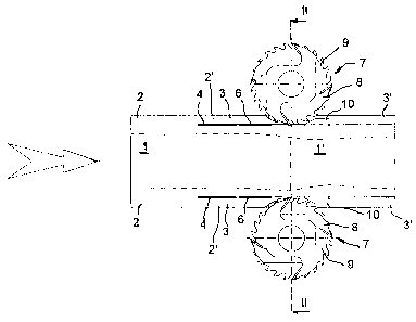
Fig. 1 presents a simplified illustration of the
procedure of the invention as seen from above,
Fig. 2 illustrates the edging stage of the procedure
of the invention, sectioned along line II in
Fig. 1, and
Fig. 3 presents a simplified illustration of the
procedure of the invention in side view.
From a tree trunk 1 trimmed at least on two sides and
having unmachined dull edges 2, at least one side board
3 is sawn by means of a saw 4. In the embodiment
depicted, the saw Q is a log band saw, but a circular
saw or other type of saw applicable for sawing the side
boards can also be used. The feed direction of the trunk
1 is indicated with an arrow in Fig. 1. The side board
or side boards are preferably sawn in such a way that at
least part of the dull edges 2 remain on the side
boards. In the embodiment illustrated by the figures,

21R~~21
3
there are preferably two saws 4, so the side boards 3 are
sawn simultaneously from both sides of the trunk.
Between the side board 3 and the central section 1'
there is a dividing and guiding element, such as a
dividing knife 6, which keeps the side board 3 and the
central section 1' apart from each other at least during
the edging operation after the sawing.
l0 After the sawing operation described above, the dull
edge 2' remaining on the side board 3 is machined with a
chipping head 7. The side board 3 is moved together with
the central section 1' during edging and the side board
3 and central section 1' are kept at a distance from
each other at least during the edging operation. The
chipping head 7 is preferably provided with a chipping
edger 8, which again is provided with a circular saw
blade 9 on its side surface. The diameter of the
circular saw blade 9 corresponds to the diameter of the
chipping edger 8. The chipping head chips the dull edge
2' and at the same time saws the lateral surface of the
side board 3 on the side facing towards the chipping
head. The side board 3 is supported, preferably
immediately after the edging operation, by means of a
supporting element 10, which preferably moves along with
the movement of the chipping head 7. Thus, the position
of the side board relative to the central section is
maintained.
3o The edging is performed substantially immediately after
the sawing. The distance between these two operations
depends on the practical application. A typical distance
of the supporting element 10 from the sawing point is of
the order of 0.5 - 1.5 m when a circular saw is used to
saw the side boards. In the case of a band saw, the
distance is typically shorter.

21q ( 12J
4
As the edging of the side boards 3 is done in separation
from the central section 1', preferably using a dividing
knife 6, an undamaged central section is obtained. There
are preferably four chipping heads 7, two on either side
of the central section 1' . Fig. 2 presents a simplified
illustration of the edging operation.
After the edging, square-edged side boards 3' and
central section 1' are thus obtained. The procedure can
to be used in connection with both the so-called double
cutting and the resawing of cants.
The procedure of the invention can also be applied in
cases where several side boards are sawn at the same
time from both sides of the trunk. In a typical
embodiment, at first two side boards are sawn from
either side of the trunk, whereupon the dull edges of
each side board are edged. In this case, adjacent side
boards can be sawn in a manner known in itself, e.g.
using band saws placed side by side, and the chipping
heads used for the edging are disposed e.g. in a
stepwise manner so that the chipping heads for the outer
side boards are placed foremost and after them the
chipping heads for the edging of the inner side boards.
The inner and outer side boards are kept at a distance
from each other using e.g. a dividing knife at least
during the edging of the outer side board, and the inner
side board and the central section are kept at a
distance from each other at least during the edging of
3o the inner side board.
It is obvious to a person skilled in the art that the
invention is not restricted to the embodiment described
above, but that it can be varied in the scope of the
attached claims.

Representative Drawing
A single figure which represents the drawing illustrating the invention.
Administrative Status

2024-08-01:As part of the Next Generation Patents (NGP) transition, the Canadian Patents Database (CPD) now contains a more detailed Event History, which replicates the Event Log of our new back-office solution.

Please note that "Inactive:" events refers to events no longer in use in our new back-office solution.

For a clearer understanding of the status of the application/patent presented on this page, the site Disclaimer , as well as the definitions for Patent , Event History , Maintenance Fee  and Payment History  should be consulted.

Event History

Description Date
Inactive: Expired (new Act pat) 2016-11-22
Inactive: Correspondence - MF 2010-08-10
Inactive: Office letter 2006-10-12
Inactive: Corrective payment - s.78.6 Act 2006-10-05
Inactive: IPC from MCD 2006-03-12
Grant by Issuance 2005-04-12
Inactive: Cover page published 2005-04-11
Pre-grant 2005-01-28
Inactive: Final fee received 2005-01-28
Notice of Allowance is Issued 2004-10-25
Letter Sent 2004-10-25
Inactive: Approved for allowance (AFA) 2004-10-15
Amendment Received - Voluntary Amendment 2004-04-02
Inactive: Entity size changed 2003-11-13
Inactive: S.29 Rules - Examiner requisition 2003-10-07
Inactive: S.30(2) Rules - Examiner requisition 2003-10-07
Inactive: Status info is complete as of Log entry date 2001-04-24
Letter Sent 2001-04-24
Inactive: Application prosecuted on TS as of Log entry date 2001-04-24
Request for Examination Requirements Determined Compliant 2001-03-21
All Requirements for Examination Determined Compliant 2001-03-21
Application Published (Open to Public Inspection) 1997-05-25

Abandonment History

There is no abandonment history.

Maintenance Fee

The last payment was received on 2004-10-27

Note : If the full payment has not been received on or before the date indicated, a further fee may be required which may be one of the following

  • the reinstatement fee;
  • the late payment fee; or
  • additional fee to reverse deemed expiry.

Please refer to the CIPO Patent Fees web page to see all current fee amounts.

Owners on Record

Note: Records showing the ownership history in alphabetical order.

Current Owners on Record
KAUKO RAUTIO
Past Owners on Record
None
Past Owners that do not appear in the "Owners on Record" listing will appear in other documentation within the application.
Documents

To view selected files, please enter reCAPTCHA code :


To view images, click a link in the Document Description column. To download the documents, select one or more checkboxes in the first column and then click the "Download Selected in PDF format (Zip Archive)" or the "Download Selected as Single PDF" button.

List of published and non-published patent-specific documents on the CPD .

If you have any difficulty accessing content, you can call the Client Service Centre at 1-866-997-1936 or send them an e-mail at CIPO Client Service Centre.


Document
Description 
Date
(yyyy-mm-dd) 
Number of pages   Size of Image (KB) 
Representative drawing 1997-08-28 1 13
Cover Page 1998-06-25 1 15
Description 1997-03-27 4 172
Claims 1997-03-27 2 44
Abstract 1997-03-27 1 17
Cover Page 1997-03-27 1 15
Drawings 1997-03-27 2 28
Description 2004-04-02 5 193
Claims 2004-04-02 2 44
Representative drawing 2004-10-19 1 10
Cover Page 2005-03-14 1 38
Reminder of maintenance fee due 1998-07-23 1 115
Acknowledgement of Request for Examination 2001-04-24 1 178
Commissioner's Notice - Application Found Allowable 2004-10-25 1 162
Fees 1998-10-08 1 34
Fees 2001-11-15 1 32
Fees 2002-10-17 1 30
Fees 1999-10-06 1 30
Fees 2000-10-17 1 31
Correspondence 2005-01-28 1 24
Correspondence 2006-10-05 4 142
Correspondence 2006-10-12 1 14
Correspondence 2010-08-10 1 46
Fees 1997-03-13 1 88