Language selection

Search

Patent 2191168 Summary

Third-party information liability

Some of the information on this Web page has been provided by external sources. The Government of Canada is not responsible for the accuracy, reliability or currency of the information supplied by external sources. Users wishing to rely upon this information should consult directly with the source of the information. Content provided by external sources is not subject to official languages, privacy and accessibility requirements.

Claims and Abstract availability

Any discrepancies in the text and image of the Claims and Abstract are due to differing posting times. Text of the Claims and Abstract are posted:

  • At the time the application is open to public inspection;
  • At the time of issue of the patent (grant).
(12) Patent: (11) CA 2191168
(54) English Title: STRAP SEVERING AND EJECTING APPARATUS AND METHOD FOR STRAPPING MACHINE
(54) French Title: APPAREIL POUR COUPER PUIS EJECTER LES FEUILLARDS ET METHODE POUR CERCLEUSE
Status: Deemed expired
Bibliographic Data
(51) International Patent Classification (IPC):
  • B65B 13/04 (2006.01)
  • B65B 13/16 (2006.01)
  • B65B 13/22 (2006.01)
  • B65H 23/04 (2006.01)
  • B65H 26/02 (2006.01)
(72) Inventors :
  • BELL, LEMUEL (LEM) J., JR. (United States of America)
  • PEARSON, TIM (United States of America)
(73) Owners :
  • ILLINOIS TOOL WORKS INC. (United States of America)
(71) Applicants :
  • ILLINOIS TOOL WORKS INC. (United States of America)
(74) Agent: FINLAYSON & SINGLEHURST
(74) Associate agent:
(45) Issued: 2002-09-10
(22) Filed Date: 1996-11-25
(41) Open to Public Inspection: 1997-06-16
Examination requested: 1996-11-25
Availability of licence: N/A
(25) Language of filing: English

Patent Cooperation Treaty (PCT): No

(30) Application Priority Data:
Application No. Country/Territory Date
08/573,326 United States of America 1995-12-15

Abstracts

English Abstract


An automatic strap severing and ejecting apparatus and method for a
strapping machine is provided. The strap severing device of the present
invention
cooperates with the tensioning and feed wheels, allowing the tensioning and
feed wheels
to serve a dual function, one function during normal operation and a second
function
during automatic severing and ejecting of strap error from the strapping
machine.


Claims

Note: Claims are shown in the official language in which they were submitted.


4
The embodiments of the invention in which an exclusive property or privilege
is claimed
are defined as follows:
1. An automatic strap severing and ejecting apparatus for a strapping
machine, comprising:
strap feeding means for feeding a strap along a normal strap travel path
during normal operation of said machine;
strap tensioning means cooperating with said strap feeding means for
tensioning said strap fed along said normal strap travel path by said strap
feeding means
during said normal operation of said machine; and
strap cutting means interposed between said strap tensioning means and
said strap feeding means and disposed along said normal strap travel path so
as to be
unobtrusive to strap travel during normal operation of said machine but being
operable
to sever a strap and direct a downstream section of the severed strap toward
an ejection
path when a strap malfunction occurs;
said strap tensioning means also being operable during said strap
malfunction occurrence so as to convey said downstream section of said severed
strap
along said ejection path and eject said downstream section of said severed
strap out of
said machine.
2. An automatic strap severing and ejecting apparatus for a strapping
machine as claimed in claim 1, wherein said strap cutting means comprises:
a rotatable strap cutter element having a rotating cutting surface located
along an edge of said rotatable strap cutter element; and
a fixed cutting surface separate from and disposed adjacent to said rotating
cutting surface such that a strap segment to be severed is disposed between
said rotating
cutting surface and said fixed cutting surface wherein rotation of said
rotatable strap
cutter element through a cutting cycle causes said rotating cutting surface of
said
rotatable strap cutter element to be disposed against said strap segment to be
severed
and then moves said rotating cutting surface of said rotatable strap cutter
element
through said strap and toward said fixed cutting surface until said strap is
severed.


5
3. An automatic strap severing and ejecting apparatus for a strapping
machine as claimed in claim 2, wherein:
said strap tensioning means comprises first and second tension wheels;
said strap feeding means comprises first and second feed wheels; and
said rotatable strap cutter element is disposed between said first and
second tension wheels and said first and second feed wheels the first and
second tension
wheels being rotatable to withdraw a segment of strap from the strapping
machine and
deliver the segment of strap to the ejector path and ultimately out of the
strapping
machine, wherein the first and second tension wheels serve the dual function
of
tensioning the strap during normal operation and ejection the strap segment
from the
strapping machine in the event of a strap error.
4. An automatic strap severing and ejecting apparatus for a strapping
machine as claimed in claim 3, further comprising:
a pivotable strap guide disposed adjacent to said second tension wheel so
as to be pivotable away from said normal strap travel path during a strap
malfunction
severing and ejection cycle wherein rotation of said pivotable strap guide
away from said
normal strap travel path opens said ejection path to said severed strap
segment to be
ejected.
5. An automatic strap severing and ejecting apparatus for a strapping
machine as claimed in claim 4, wherein the pivotable strap guide is spring
loaded.
6. An automatic strap severing and ejecting apparatus for a strapping
machine as claimed in claim 5, further comprising a gear motor which rotates
the strap
cutter element through its range of rotation.
7. An automatic strap severing and ejecting apparatus for a strapping
machine as claimed in claim 6, further comprising a strap cutter sleeve which
houses the
strap cutter element, the strap cutter sleeve being stationary.
8. An automatic strap severing and ejecting apparatus for a strapping


6
machine as claimed in claim 4, further comprising:
means for driving said first and second feed wheels so as to refeed said
strap into said strapping machine after completion of said strap segment
ejection cycle.
9. An automatic strap severing and ejecting apparatus for a strapping
machine, comprising:
strap feeding means for feeding a strap along a normal strap travel path
during normal operation of said machine;
strap cutting means disposed along said normal strap travel path so as to
be unobtrusive to strap travel during normal operation of said machine but
being
operable to sever a strap and direct a downstream section of said severed
strap toward
an ejection path when a strap malfunction occurs; and
dual-function strap tensioning means for tensioning said strap fed along
said normal strap travel path by said strap feeding means during said normal
operation
of said machine and for conveying said downstream section of said severed
strap along
said ejection path for ejection of said downstream section of said severed
strap out of
said machine following said strap malfunction occurrence.
10. Apparatus as set forth in claim 9, wherein:
said strap cutting means is interposed between said strap feeding means
and said strap tensioning means.
11. Apparatus as set forth in claim 9, wherein said strap cutting means
comprises:
a rotatable strap cutter element having a rotating cutting surface located
along an edge of said rotatable strap cutter element; and
a fixed cutting surface separate from and disposed adjacent to said rotating
cutting surface such that a strap segment to be severed is disposed between
said rotating
cutting surface and said fixed cutting surface wherein rotation of said
rotatable strap
cutter element through a cutting cycle causes said rotating cutting surface of
said
rotatable strap cutter element to be disposed against said strap segment to be
severed
and then moves said rotating cutting surface of said rotatable strap cutter
element

7
through said strap and toward said fixed cutting surface until said strap is
severed.
12. Apparatus as set forth in claim 11, wherein:
said strap tensioning means comprises a pair of tension wheels;
said strap feeding means comprises a pair of feed wheels; and
said rotatable strap cutter element is interposed between said feed wheels
and said tension wheels.
13. Apparatus as set forth in claim 12, further comprising:
a pivotable strap guide disposed adjacent to said tension wheels so to be
pivotable away from said normal strap travel path during a strap malfunction
severing
and ejection cycle wherein rotation of said pivotable strap guide away from
said normal
strap travel path opens said ejection path to said severed strap segment to be
ejected
from said machine.
14. A method of operating a strapping machine during normal operation and
malfunction cycles, comprising the steps of:
providing strap feeding means for feeding a strap along a normal strap
travel path during a normal operation cycle of said machine;
providing strap tensioning means for tensioning said strap fed along said
normal strap travel path by said strap feeding means during said normal
operation cycle
of said machine;
providing strap cutting means disposed along said normal strap travel path
so as to be movable between a first position at which said strap cutting means
is
unobtrusive to travel of said strap along said normal strap travel path during
said
normal operation cycle of said machine and a second position at which said
strap cutting
means severs said strap when a strap malfunction occurs and directs a
downstream
section of said severed strap toward an ejection path during a strap
malfunction
operation cycle;
operating said strap feeding means and said strap tensioning means, while
said strap cutting means is disposed at said first position, so as to convey
said strap
along said normal strap travel path during a normal operation cycle of said
machine;


8
moving said strap cutting means from said first position to said second
position when a strap malfunction occurs so as to sever said strap and direct
a
downstream section of said severed strap toward said ejection path; and
operating said strap tensioning means for conveying said downstream
section of said severed strap along said ejection path for ejection of said
downstream
section of said severed strap out of said machine during a strap malfunction
operation
cycle.
15. The method as set forth in claim 14, further comprising the steps of:
providing first and second feed wheels so as to comprise said strap feeding
means;
providing first and second tension wheels so as to comprise said strap
tensioning means; and
interposing said strap cutting means between said first and second feed
wheels and said first and second tension wheels.
16. The method as set forth in claim 14, further comprising the step of:
interposing said strap cutting means between said strap feeding means and
said strap tensioning means.
17. The method as set forth in claim 14, further comprising the steps of:
providing said strap cutting means as a rotatable strap cutting element;
and
rotating said rotatable strap cutting element between said first and second
positions when said machine is being operated during said normal operation and
strap
malfunction operation cycles, respectively.
18. The method as set forth in claim 14, further comprising the step of:
providing a pivotable strap guide in conjunction with said strap tensioning
means; and
pivoting said pivotable strap guide away from said normal strap travel
path during said strap malfunction operation cycle so as to uncover said
ejection path


9


and thereby permit said downstream section of said severed strap to be
conveyed along
said ejection path and ejected out from said machine.

Description

Note: Descriptions are shown in the official language in which they were submitted.


CA 02191168 2001-11-29
1
TITLE OF INVENTION
STRAP SEVERING AND EJECTING APPARATUS AND METHOD FOR
STRAPPING MACHINE
BACKGROUND OF THE INVENTION
Field of the Invention:
The present invention relates to strap severing and ejecting apparatus and
methods for strapping machines. In particular, the invention relates to a
device which
automatically severs and ejects strap errors from the strapping machine.
Description of Related Art:
In the past, severing and ejecting strap errors from a strapping machine
involved complex components which were not completely integrated into the
entire
strapping machine by virtue of their separate functions. For example, related
prior art
U.S. Patent No. 5,287,802 requires a separate feeding and tensioning apparatus
to
automatically sever and eject strap errors. Provision of separate components
with
dedicated duty related specifically to severing and rejecting strap errors
leads to
problems of additional mechanical complexity and the related maintenance
disadvantages, additional electronic control systems and consequent higher
cost.
These and other related problems arc solved by the invention disclosed
herein.
SUMMARY OF THE INVENTION
The present invention embodies many advantages over prior art systems
for severing and ejecting strap errors in a strapping machine.
The present invention seeks to provide for the automatic severing and
ejecting of strap errors from a strapping machine and one utilizing a system
which may
be integral with the other standard functions of a strapping machine.
The invention in one broad aspect pertains to an automatic strap severing
and ejecting apparatus for a strapping machine, comprising strap feeding means
for
feeding a strap along a normal strap travel path during normal operation of
the
machine, strap tensioning means cooperating with the strap feeding means for
tensioning
the strap fed along the normal strap travel path by the strap feeding means
during the
normal operation of the machine and strap cutting means interposed between the
strap
tensioning means and the strap feeding means and disposed along the normal
strap

CA 02191168 2001-11-29
2
travel path so as to be unobtrusive to strap travel during normal operation of
the
machine but being operable to sever a strap and direct a downstream section of
the
severed strap toward an ejection path when a strap malfunction occurs. The
strap
tensioning means also is operable during the strap malfunction occurrence so
as to
convey the downstream section of the severed strap along the ejection path and
eject the
downstream section of the severed strap out of the machine.
Another aspect of the invention provides an automatic strap severing and
ejecting apparatus for a strapping machine, comprising strap feeding means for
feeding
a strap along a normal strap travel path during normal operation of the
machine and
strap cutting means disposed along the normal strap travel path so as to be
unobtrusive
to strap travel during normal operation of the machine but being operable to
sever a
strap and direct a downstream section of the severed strap toward an ejection
path when
a strap malfunction occurs. Dual-function strap tensioning means is provided
for
tensioning the strap fed along the normal strap travel path by the strap
feeding means
during the normal operation of the machine and for conveying the downstream
section
of the severed strap along the ejection path for ejection of the downstream
section of the
severed strap out of the machine following the strap malfunction occurrence.
Still further the invention comprehends a method of operating a strapping
machine during normal operation and malfunction cycles, comprising the steps
of
providing strap feeding means for feeding a strap along a normal strap travel
path
during a normal operation cycle of the machine, providing strap tensioning
means for
tensioning the strap fed along the normal strap travel path by the strap
feeding means
during the normal operation cycle of the machine and providing strap cutting
means
disposed along the normal strap travel path so as to be movable between a
first position
at which the strap cutting means is unobtrusive to travel of the strap along
the normal
strap travel path during the normal operation cycle of the machine and a
second
position at which the strap cutting means severs the strap when a strap
malfunction
occurs and directs a downstream section of the severed strap toward an
ejection path
during a strap malfunction operation cycle. The strap feeding means and the
strap
tensioning means are operated while the strap cutting means is disposed at the
first
position, so as to convey the strap along the normal strap travel path during
a normal
operation cycle of the machine and the strap cutting means is moved from the
first

CA 02191168 2001-11-29
2A
position to the second position when a strap malfunction occurs so as to sever
the strap
and direct a downstream section of the severed strap toward the ejection path.
The
strap tensioning means operates for conveying the downstream section of the
severed
strap along the ejection path for ejection of the downstream section of the
severed strap
out of the machine during a strap malfunction operation cycle.
These and other aspects of the invention are achieved by the present
invention.
BRIEF DESCRIPTION OF THE DRAWINGS
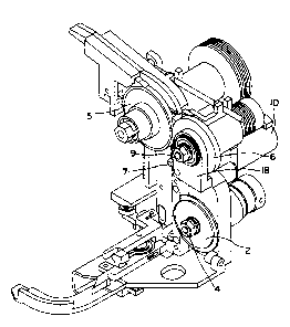
Figure 1 is a front view of the present invention.
Figure 2 is a top right perspective view of the present invention.
DESCRIPTION OF THE PREFERRED EMBODIIVVIENT
Referring to Figure 1, the strap severing and ejecting apparatus of the
present invention provides a strap cutter element 7 located between a first
and second
tension wheel set 5, 6 and a first and second feed wheel set 1, 2.
The strap cutter element rotates about a strap cutter axis 8 and may be
disposed within a strap cutter sleeve 9. During normal operation of the
strapping machine, the strap passes undisturbed along an edge of the strap
cutter
element 7 through normal path 17. However, in the event of a strap error
downstream
of the tension wheel, the strap cutter element 7 rotates in a direction which
positions a
strap segment between a rotating cutting surface 20 of the strap cutter
element 7 and a fixed cutting surface 19. Continued rotation of the strap
cutter


2191~.~~
3
element 7 severs the strap at that point, and also directs the downstream
portion of the
severed strap 16, including the strap error, into an ejection path 11, while
at the same time
blocking the normal path 17. A pivotable strap guide 18 which may be disposed
about
second tension wheel 6 is rotated to open a clear ejection path for ejection
of the strap
error segment. The pivotable strap guide 18 may be spring loaded.
The same first and second tension wheels S, 6 which are utilized during
normal operation of the strapping device are now operated to withdraw the
strap 16
including the strap error out of the strapping machine for disposal or
recycling. A gear
motor 10 may be utilized to rotate the strap cutter element 7 between the
normal position
and the cuttinglejection position. A linkage may be provided for use in
connection with
the gear motor IO to limit the angular displacement of the rotating strap
cutter element 7.
After the strap error has been completely rejected from the strapping
machine, the first and second feed wheels refeed the strap through the normal
path 17, past
the strap cutter element 7 which has been returned to its normal operation
position, and
up through the chute for the next strapping job.
In this manner, the first and second feed wheels 1, 2, and the first and
second tension wheels 5, 6, serve dual functions, one function during normal
strapping
conditions, and a second function during the automatic strap ejection
procedure. The dual
function of the feed and tension wheels allows for a simplification and
reduction of the
total elements necessary for the strapping machine to carry out the required
functions.
This leads to cost reductions, maintenance simplification, and reliability
increases over
prior art strapping machines.
The invention desctibed above also encompasses the range of equivalents
to which it is entitled, and is only limited by the following claims.

Representative Drawing
A single figure which represents the drawing illustrating the invention.
Administrative Status

For a clearer understanding of the status of the application/patent presented on this page, the site Disclaimer , as well as the definitions for Patent , Administrative Status , Maintenance Fee  and Payment History  should be consulted.

Administrative Status

Title Date
Forecasted Issue Date 2002-09-10
(22) Filed 1996-11-25
Examination Requested 1996-11-25
(41) Open to Public Inspection 1997-06-16
(45) Issued 2002-09-10
Deemed Expired 2012-11-26

Abandonment History

There is no abandonment history.

Payment History

Fee Type Anniversary Year Due Date Amount Paid Paid Date
Registration of a document - section 124 $100.00 1996-11-25
Application Fee $0.00 1996-11-25
Maintenance Fee - Application - New Act 2 1998-11-25 $100.00 1998-11-16
Maintenance Fee - Application - New Act 3 1999-11-25 $100.00 1999-11-09
Maintenance Fee - Application - New Act 4 2000-11-27 $100.00 2000-11-06
Maintenance Fee - Application - New Act 5 2001-11-26 $150.00 2001-11-05
Final Fee $300.00 2002-06-21
Maintenance Fee - Patent - New Act 6 2002-11-25 $150.00 2002-10-31
Maintenance Fee - Patent - New Act 7 2003-11-25 $150.00 2003-11-03
Maintenance Fee - Patent - New Act 8 2004-11-25 $200.00 2004-11-04
Maintenance Fee - Patent - New Act 9 2005-11-25 $200.00 2005-11-02
Maintenance Fee - Patent - New Act 10 2006-11-27 $250.00 2006-10-30
Maintenance Fee - Patent - New Act 11 2007-11-26 $250.00 2007-10-30
Maintenance Fee - Patent - New Act 12 2008-11-25 $250.00 2008-10-30
Maintenance Fee - Patent - New Act 13 2009-11-25 $250.00 2009-10-30
Maintenance Fee - Patent - New Act 14 2010-11-25 $250.00 2010-11-01
Owners on Record

Note: Records showing the ownership history in alphabetical order.

Current Owners on Record
ILLINOIS TOOL WORKS INC.
Past Owners on Record
BELL, LEMUEL (LEM) J., JR.
PEARSON, TIM
Past Owners that do not appear in the "Owners on Record" listing will appear in other documentation within the application.
Documents

To view selected files, please enter reCAPTCHA code :


To view images, click a link in the Document Description column. To download the documents, select one or more checkboxes in the first column and then click the "Download Selected in PDF format (Zip Archive)" or the "Download Selected as Single PDF" button.

List of published and non-published patent-specific documents on the CPD .

If you have any difficulty accessing content, you can call the Client Service Centre at 1-866-997-1936 or send them an e-mail at CIPO Client Service Centre.


Document
Description 
Date
(yyyy-mm-dd) 
Number of pages   Size of Image (KB) 
Representative Drawing 1998-05-22 1 30
Abstract 2002-01-04 1 13
Description 2001-11-29 4 191
Claims 2001-11-29 6 234
Drawings 2001-11-29 2 54
Drawings 1998-01-07 2 61
Abstract 1997-04-07 1 13
Cover Page 1997-06-17 1 16
Description 1997-04-07 3 115
Claims 1997-04-07 2 75
Drawings 1997-04-07 2 60
Representative Drawing 2001-12-28 1 15
Cover Page 2002-08-07 1 41
Prosecution-Amendment 2001-08-17 2 45
Prosecution-Amendment 2001-11-29 16 586
Correspondence 2002-06-21 1 33
Assignment 1996-11-25 12 413
Correspondence 1997-01-07 4 127