Note: Descriptions are shown in the official language in which they were submitted.
21~ia80
ELECTRIC ADJUSTER
BACKGROUND OF THE INVENTION
1. Field of the Invention
The present invention relates to voltage or current
adjusting means which is indispensable to an electric control
unit such as a stabilized power supply unit, an electric
motor control unit, a power control unit or a variety of
power supply units. The present invention also relates to a
static type voltage or current adjuster (hereinafter referred
to as "electric adjuster") of a novel system which is high in
efficiency, high in response speed, small in size, light in
weight, limitless in load power factor, and relatively simple
to make the accuracy high without generating a power-supply
harmonic current.
2. Description of the Related Art
Nowadays, as a result of miniaturizing of electronic
components and a high integration, electronic equipment is
small in size, light in weight, low in cost and high in
efficiency with an enhancement of their function and accuracy
year by year. However, because of the characteristics
inherent in a power converter, progress similar to that made
in other electronic equipment has not been realized.
Basically, the electric control units have been designed
using old techniques. Besides, new designs such as a
thyristor phase control system or a switching system, cause
electromagnetic interference in other electronic equipment
- 1 -
211480
during the switching operation or cause a harmonic current
which is generated during the switching operation adversely
affects an electric power system of an electric power
company. For the above and other reasons, great progress
using the conventional techniques could not be expected.
As the control systems for the conventional electric
adjuster, the CVT system, the sliding system, the magnetic
amplifier system, the tap switching system, the thyristor
phase control system and the switching system are mainly
employed. The main performance requirements for the electric
adjuster of the electric control unit include high
efficiency, a high-speed response, a small size with light
weight, no power-supply higher harmonics, no limitation of
load power factor, simple to achieve high precision, a high
reliability, low cost, no moving parts, and so on.
In case of the sliding system (rheostat), since it is
not of the static type but has a movable portion, frequent
repairs are required, and the reliability is low. Also,
there are limitations on making the efficiency high, the
response speed high, the size small, the weight light and the
precision high. In case of the CVT system and the magnetic
amplifier system, because they have no moving parts, although
the reliability is high, they are very heavy in weight, and
therefore, there are limitations on making the efficiency
high, the response speed high, the size small with light
weight and the precision high. In case of the tap switching
system, the switching period is long, and the control
resolution is low. In addition, there are limitations on
- 2 -
219i~~~
making the efficiency high, the size small and the weight
light. In case of the thyristor phase control system and the
switching system, there arise problems such as
electromagnetic interference caused by the distortion of an
output voltage waveform or the generation of switching noise,
and a harmonic current, and also a problem because it cannot
be used for a load low in power factor. Moreover, there are
also limitations on making the efficiency high, the response
speed high, and the size small with light weight and the
precision high.
SUMMARY OF THE INVENTION
The present invention has been designed to eliminate
the problems with the conventional electric adjusters, and
therefore an object of the present invention is to provide a
novel electric adjuster to replace the control systems such
as the CVT system employed in the conventional electric
adjusters, the sliding system, the magnetic amplifier system,
the tap switching system, the thyristor phase control system
and the switching system.
Another object of the present invention is to provide
a static type electric adjuster which is improved with the
results of a high efficiency, a high-speed response, a small
size, a light weight, no power-supply higher harmonic, no
limitation of a load power factor, the simplification of
making the accuracy high, a high reliability and low costs,
which are performances required for the electric adjuster for
an electric control unit.
- 3 -
2~9~~8~
In case of converting an a.c. voltage from a certain
value to another value, it is well known that it is best to
use a transformer. The ratio of transformation is determined
in accordance with the winding ratio of the transformer.
According to the present invention, for the purpose of making
a voltage variable with a high performance, a plurality of
coils are disposed on a primary side, a secondary side or
both of the primary and secondary sides of the transformer,
and the connection of the coils is switched with an arbitrary
combination of connections such as a series connection or a
parallel connection, thereby being capable of continuously
varying the ratio of composite windings between the primary
side and the secondary side.
When a plurality of coils are combined by a series
connection through a binary system which is well known in the
digital field, the number of combinations is 2n (n is the
number of coils) with the result that the ratio of windings
can be adjusted over a wider range using a reduced number of
coils. For example, 16 different combinations are enabled
with 4 coils, 256 different combinations are enabled with 8
coils, and 1024 different combinations are enabled with 10
coils.
When the digital transformer thus constituted with the
variable number of windings is used as a series transformer
for the voltage adjuster of a series transformer system, a
voltage adjuster with a higher performance can be provided,
and very flexible control can be performed by controlling the
ratio of windings through a microcomputer.
- 4 -
2i~i~~0
The above and other objects and features of the
present invention will be more apparent from the following
description taken in conjunction with the accompanying
drawings.
BRIEF DESCRIPTION OF THE DRAWINGS
Fig. 1 is a block diagram showing a main electric
circuit of an electric adjuster in accordance with one
embodiment of the present invention;
Fig. 2 is a block diagram showing a main electric
circuit of an electric adjuster in accordance with another
embodiment of the present invention; and
Fig. 3 is a block diagram showing a main electric
circuit of an electric adjuster in accordance with still
another embodiment of the present invention.
DETAILED DESCRIPTION OF THE PREFERRED EMBODIMENTS
Now, a description will be given in more detail of
preferred embodiments of the present invention with reference
to the accompanying drawings.
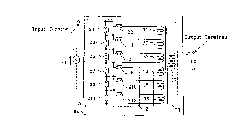
Fig. 1 is a block diagram showing a main electric
circuit of an electric adjuster with 6 primary coils in
accordance with one embodiment of the present invention. As
shown in Fig. 1, the main electric circuit includes an a.c.
power supply 1 providing a primary-side input voltage; a
transformer 3 having a secondary coil 37 and a plurality of
primary coils 31, 32, 33, 34, 35 and 36 whose ratios of
windings to the secondary coil 37 are 1, 2, 4, 8, 16 and 32,
- 5 -
2~~~~s
respectively; and a coil switching operation section 2 that
switches the combinations of the plural primary coils 31 to
36 using a plurality of switches 21, 22, 23, 24, 25, 26, 27,
28, 29, 210, 211 and 212, to make the number of composite
windings variable, with the result that the ratio of windings
on the primary coils to the windings on the secondary coil
winding is continuously digitally adjusted.
Since the ratio of primary windings (al) to the
secondary windings can be continuously digitally varied from
1 to 63 with the operation of the coil switching operation
section 2, an output voltage E2 is expressed by E1/al where
E1 is an input voltage, thus being capable of adjusting a
voltage. The ratios of windings on the primary coils 31 to
36 to the windings on the secondary coil 37 do not have to be
1, 2, 4, 8, 16 and 32, respectively. They can be determined
arbitrarily in accordance with a purpose. Likewise, the
number of the primary coils can be arbitrarily determined in
accordance with the purpose so long as it is two or more .
Further, a tap may be disposed on each of the primary coils
or the secondary coil so as to provide a more complicated
adjusting function. Alternatively, a plurality of
independent transformers may be provided instead of the
transformer 3 so as to be connected in the same manner as
above to obtain the equivalent function.
Fig. 2 is a block diagram showing a main electric
circuit of an electric adjuster with 6 secondary coils in
accordance with one embodiment of the present invention. As
shown in Fig. 2, the main electric circuit includes an a.c.
- 6 -
2i?1a~L
power supply 1 providing a primary-side input voltage; a
transformer 4 having a primary coil 47 and a plurality of
secondary coils 41, 42, 43, 44, 45 and 46 whose ratios of
windings to the primary coil 47 are 0.01, 0.02, 0.04, 0.08,
0.16 and 0.32, respectively; and a coil switching operation
section 5 that switches the combinations of the plural
secondary coils 41 to 46 using a plurality of switches 51,
52, 53, 54, 55, 56, 57, 58, 59, 510, 511 and 512, to make the
number of composite windings variable, with the result that
the ratio of secondary windings to the primary winding is
continuously digitally adjusted.
Since the ratio of windings (a2) on the secondary coil
to the winding on the primary coil can be continuously
digitally varied from 0.1 to 0.63 with the operation of the
coil switching operation section 5, an output voltage E2 is
expressed by E1 X a2 where E1 is an input voltage, thus being
capable of adjusting a voltage with the resolution of E1 X
0.01. The ratios of the windings on the secondary coils 41
to 46 to the windings on the primary coil 47 do not have to
be 0.01, 0.02, 0.04, 0.08, 0.16 and 0.32, respectively. They
can be determined arbitrarily in accordance with a purpose.
Likewise, the number of the secondary coils can be
arbitrarily determined in accordance with a purpose, as long
as it is two or more. Further, a tap may be disposed on each
of the secondary coils or the primary coil so as to provide
a more complicated adjusting function. Alternatively, a
plurality of independent transformers may be used instead of
_ 7 _
2191~~(
the transformer 4 and connected in the same manner as above
to obtain an equivalent function.
Fig. 3 is a block diagram showing a main electric
circuit of an electric adjuster with 6 primary coils and 6
secondary coils in accordance with still another embodiment
of the present invention. As shown in Fig. 3, the main
electric circuit includes an a.c. power supply 1 providing a
primary-side input voltage; a transformer 6 having primary
coils 61, 62, 63, 64 and 66 whose ratios of windings to the
windings on a secondary coil 67 with the smallest number of
windings is 1, 2, 4, 8, 16 and 32, respectively, and
secondary coils 67, 68, 69, 610, 611 and 612 whose ratios of
windings to the windings on the primary coil 61 with the
smallest number of winding is 0.01, 0.02, 0.04, 0.08, 0.16
and 0.32, respectively; a coil switching operation section 7
that switches the combinations of the plural primary windings
61 to 66 by a plurality of switches 71, 72, 73, 74, 75, 76,
77, 78, 79, 710, 711 and 712, to make the number of composite
windings variable, with the result that the ratio of primary
windings to the secondary windings are continuously digitally
adjusted; and a coil switching operation section 8 that
switches the combinations of the plural secondary coils 67 to
69, 610, 611 and 612 by a plurality of switches 81, 82, 83,
84, 85, 86, 87, 88, 89, 810, 811 and 812, to make the number
of composite windings variable, with the result that the
ratio of secondary windings to the primary windings are
continuously digitally adjusted.
_ g _
2a~~~~~
Since the ratio of windings (al) to the windings on
the secondary coils can be continuously digitally varied from
1 to 63 with the operation of the coil switching operation
section 7, and also the ratio of windings (a2) on the primary
winding can be continuously digitally varied from 0.01 to
0.63 with the operation of the coil switching operation
section 8, an output voltage E2 is expressed by E1 X a2/al
where E1 is an input voltage, thus being capable of adjusting
a voltage over a relatively wide range or relatively finely.
The combinations of the ratios of windings on the primary
coils as well as the secondary coils can be arbitrarily
determined in accordance with a purpose. Likewise, the
number of the primary and secondary coils can be arbitrarily
determined in accordance with the purpose, respectively, if
they are two or more. Further, a tap may be disposed on each
of the primary and secondary coils so as to provide a more
complicated adjusting function. Alternatively, a plurality
of independent transformers may be provided instead of the
transformer 6 so as to be connected in the same manner as
above to obtain the equivalent function.
In any embodiment, the electric adjuster can be used
as a constant-voltage adjuster if the coil switching
operation section is automatically operated by monitoring an
output voltage. Similarly, the electric adjuster can be used
as a constant-current adjuster if the coil switching
operation section is automatically operated by monitoring an
output current.
g _
2191480
In addition, the primary-side input voltage E1 may be
a variety of a.c. voltage/current signals such as a sensor
signal, a detection signal or a control signal instead of an
a.c. power supply, and in this case, it is effective as a
signal converter.
As was described above, the electric adjuster of the
present invention may be used as a stabilized power supply
unit, an electric motor control unit, a power control unit,
and a variety of power supply units, and so on, thereby
enabling great improvements such as making the efficiency
high, the response speed high, the size small with light
weight, no power-supply higher harmonic, no limitation of a
load power factor, and making the precision high, the
reliability high, and the cost low, thus providing economical
effects from a variety of viewpoints in the industrial field.
The foregoing description of a preferred embodiment
of the invention has been presented for purposes of
illustration and description. It is not intended to be
exhaustive or to limit the invention to the precise form
disclosed, and modifications and variations are possible in
light of the above teachings or may be acquired from practice
of the invention. The embodiment was chosen and described in
order to explain the principles of the invention and its
practical application to enable one skilled in the art to
utilize the invention in various embodiments and with various
modifications as are suited to the particular use
contemplated. It is intended that the scope of the invention
- 10 -
2.91~~80
be defined by the claims appended hereto, and their
equivalents.
- 11 -