Note: Descriptions are shown in the official language in which they were submitted.
~ ' ' _ 1 _ 219i5~~
31062100.175
HORN SWITCH JACRET
FIELI1 OF THE INVENThN
The present invention relates to a horn switch assembly
and, more particularly, to a horn switch jacket for use with a horn
switch assembly adapted for insertion into a horn switch pocket of
l0 a driver side airbag module.
BACRGROL1ND OF THE INDENTION
Driver side airbag modules, which include an airbag
cushion and an airbag module cover, are normally positioned within
a hub of a steering wheel of a motor vehicle. The hub of the
steering wheel also happens to be the same area which
conventionally includes a horn switch assembly. Accordingly, the
airbag module cover must additionally serve to actuate the horn
switch. A horn switch assembly normally includes a horn switch and
a backing plate attached to an inner surface of a horn actuation
face of the airbag module cover. The horn switch and backing plate
are usually attached to the inner surface by ultrasonic welding or
heat staking.
Many horn switch assemblies include a membrane horn
switch. Membrane switches conventionally comprise two very thin
sheets having conductive coatings thereon which are normally
separated by thin spacers. Pressure on the switch pushes the
conductive surfaces together to close a circuit and actuate the
horn. Normally, a plurality of force concentrators ars positioned
on the inner surface of the horn actuation area of the airbag
module cover to transfer driver applied pressure more efficiently
to the horn switch.
Some horn switch assemblies include a bend sensor horn
switch that includes a bend sensitive variable resistance circuit.
The resistance of the variable resistance circuit measurably
CA 02191531 2002-04-09
..
2
changes as it is bent and the variable resistance circuit is
connectable. to a horn control circuit that responds to extremely
rapid changes in resistance but not to more gradual changes caused
by, for example, temperature variations or close packing of the
horn switch within the airbag module. Normally, a plurality of
force concentrators are positioned on the inner surface' of the horn
w actuation area of the airbag module cover and a plurality of
supports are positioned on the backing plate. The force
concentrators and supports are arranged to bend the variable
resistance circuit in preferably only one axis or direction. In
addition, the force concentrators and supports are provided in the
form of elongated ribs for translating a localized driver-applied
force over a greater area of the bend sensor.
Mounting the horn switch assembly to the airbag module
cover by ultrasonic welding or heat staking has been found to be a
time consuming assembly process that increases the cost of
manufacturing the airbag module. In addition, the horn switchnis
sometimes damagedby heat staking, requiring the replacement of the
horn switch and airbag module cover. A horn switch assembly welded
to the airbag module cover requires replacing the entire airbag
module cover when replacing damaged or defective horn switches.
Furthermore, heat staking puts constraints on the design, material
and manufacture of the airbag module cover.
One alternative to mounting the horn switch assembly by
heat staking or welding is to provide a horn switch pocket in: the
airbag module for receiving and holding the horn switch assembly
against the inner surface of the horn actuation area of the airbag
3 0 module cover. An example of such a horW switch pocket is shown and
described in United States Patent No. 5,626;358 issued May 6, 1997. '
There is, therefore, a need for a horn switch assembly
that is adapted to be mounted in a horn switch pocket of an airbag
module. There is a further need for the horn switch assembly to be
provided in embodiments incorporating a membrane horn switch and a
bend sensor horn switch.
.. i ' ' 2191531
- 3 -
SOt~~fARY OF THE INV N ION
An object, therefore, of the present invention is to
provide a horn switch assembly that meets one or more of the above
needs. In carrying out this invention there is provided a horn
switch jacket for use with a horn switch as part of a horn switch
assembly for insertion into a horn switch pocket adjacent an airbag
module cover, whereby the horn switch assembly does not have to be
heat staked or welded to the airbag module cover. The horn switch
jacket comprises a jacket front cover adapted to be positioned in
front of the horn switch, and a jacket back cover adapted to be
positioned behind the horn switch. A hinge portion connects a
first edge of the jacket front cover to a first edge of the jacket
back cover, and securing means is provided for securing the jacket
back cover to the jacket front cover with the horn switch held
therebetween.
According to one aspect of the present invention, a
plurality of spaced-apart force concentrators extend rearwardly
from a rear inner surface of the jacket front cover, and the horn
switch jacket is adapted for use with a horn switch comprising a
membrane horn switch. According to another aspect of the present
invention, a plurality of spaced-apart force concentrators extend
rearwardly from a rear inner surface of the jacket front cover, a
plurality of supports extend forwardly from a front inner surface
of the jacket back cover and the horn switch jacket is adapted for
use with a bend sensor horn switch having a plurality of spaced-
apart resistive elements.
The invention together with further objects, features,
advantages and aspects thereof, will be more clearly understood
from the following description taken in connection with the
accompanying drawings.
ERTFF DESORIPTION OF THE R_AWINGS
FIG. 1 is a rear elevation view, partially cut away, of
a horn switch assembly according to the present invention;
- 2191531
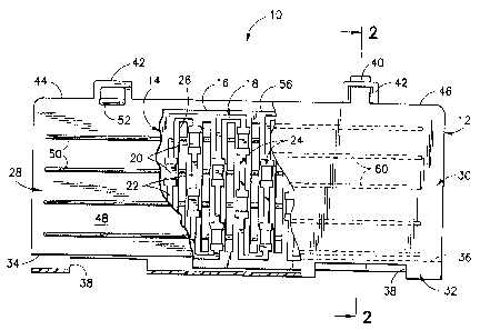
FIG. 2 is a cross sectional view of the horn switch
assembly taken along the line 2 - 2 of FIG. 1;
FIG. 3 is a rear elevation view, partially cut away, of
another horn switch assembly according to the present invention;
FIG. 4 is a cross sectional view of the horn switch
assembly taken along the line 4 - 4 of FIG. 3;
FIG. 5 is a rear elevation view, partially cut away, of
an additional horn switch assembly according to the present
invention;
FIG. 6 is a cross sectional view of the horn switch
assembly taken along the line 6 - 6 of FIG. 5;
FIG. 7 is a rear elevation view, partially cut away, of
a further horn switch assembly according to the present invention;
FIG. 8 is a cross sectional view of the horn switch
assembly taken along the line 8 - 8 of FIG. 7;
FIG. 9 is a rear elevation view, partially cut away, of
still another horn switch assembly according to the present
invention;
FIG. 10 is a cross sectional view of the horn switch
assembly taken along the line 10 - 10 of FIG. 9.
The same reference numerals refer to the same elements
throughout the various figures.
DEVILED DESGRIPTION OF THE TNtIRNTT(7N
The present invention is directed to a horn switch jacket
for use with a horn switch as part of a horn switch assembly for
insertion into a horn switch pocket adjacent an airbag module
cover. It is important to note that a horn switch jacket according
to the present invention can be adapted for use with different
types of horn switches, and can include other modifications without
departing from the true spirit and scope of the present invention.
Referring first to FIGS. 1 through 2, one possible
embodiment of a horn switch jacket 12 according to the present
invention for use with a bend sensor horn switch 14 as part of a
horn switch assembly 10 is shown. The horn switch assembly 10 is
~ - 5 - 2191531
for use in a driver side airbag module which is mounted in the hub
of an automobile steering wheel. Driver side airbag modules are
generally known in the art and, accordingly, are not described in
detail as they do not in themselves constitute features of the
present invention. The horn switch assembly 10 according to the
present invention is adapted to be mounted within an airbag module
simply by being inserted into a horn switch pocket attached to an
airbag cushion or to a cushion strap of the airbag module. A horn
switch pocket containing the horn switch assembly to is positioned
tightly between a folded airbag cushion and a horn actuation face
of an airbag module cover of the airbag module. The horn switch
assembly 10 can then be actuated by a driver pushing on the horn
actuation face of the airbag module cover.
The bend sensor horn switch 14 includes a flexible
substrate 16 and a variable resistance circuit 18 adhered to the
flexible substrate. In FIG. 2, the flexible substrate 16 and
variable resistance circuit 18 are shown with a thickness that is
substantially disproportionate to their true thickness solely to
facilitate illustration. The variable resistance circuit 18
basically comprises a flexible potentiometer which is known in the
art. An example of a flexible potentiometer is shown and described
in U.S. Patent 5,309,135. The variable resistance circuit 18 has
a plurality of spaced-apart resistive elements 20 connected by a
plurality of conductive strips 22, and the variable resistance
circuit is arranged in a plurality of parallel spaced-apart columns
24. The conductive strips 22 comprise a flexible electrical
conductive coating that may be applied to the flexible substrate 16
by any suitable means such as by screening conductive ink thereon,
for example.
The resistance of the variable resistance circuit 18
changes as the resistive elements 20 are bent. The resistive
elements 20 generally comprise a flexible electrical conductive
coating that may also be applied to the flexible substrate 16 by
any suitable means such as by screening conductive ink thereon.
The resistive elements 20 can contain flexible carbon fibers which
separate when the resistive elements 20 are bent in a particular
direction. As the carbon fibers separate the resistance of the
2191531
- 6 -
resistive elements 20 increase, changing the resistance of the
variable resistance circuit i8 which is connectable to a remote
power supply and to a remote horn control circuit utilized to
actuate a remote horn.
The remote horn control circuit closes a circuit between
the remote power supply and the remote horn when the driver presses
against the front outer face of the airbag module cover with at
least a threshold amount of force. The threshold amount of force
causes the resistive elements 2o to bend and the resistance of the
variable resistance circuit 18 to measurably change. A preferred
horn control circuit only responds to rapid changes in the
resistance of the variable resistance circuit 18 but not to more
gradual changes. Normally, thermal expansion or contraction of the
airbag module cover, curvature of the cover or close packing of the
horn switch assembly 10 and a folded airbag cushion normally
contained in an airbag module assembly may bend the resistive
elements 20 and change the resistance of the variable resistance
circuit 18 enough to inadvertently actuate the horn. However, the
rate of change of resistance is very slow. A preferred horn
control circuit prevents inadvertent actuation of the horn since
only a force applied by a driver pressing on the airbag module
cover will have the required rate of change of force or resistance
necessary to actuate the horn. Those skilled in the art will
appreciate that a-variety of circuits may be employed to carry out
the functions of a preferred horn control circuit. The horn
control circuit may include a microprocessor that can be programmed
to meet the specific requirements of an automotive manufacturer.
The flexible substrate 16 comprises electrical insulating
material such as a suitable plastic material, for example MYLAR
polyester or polyethylene with a thickness of approximately 0.10
millimeters. As shown in FIG. 1, the flexible substrate 16 also
includes slots 26 located between the columns 24 of the variable
resistance circuit 18. The slots 26 allow the resistive elements
20 in each column 24 to bend more easily in substantially one
direction and, in the alternative, the flexible substrate 16 could
simply include slits located on opposites sides of each column 24
of the variable resistance circuit 18.
2191531
_,_
The horn switch jacket 12 is folded, like a book cover,
over the bend sensor horn switch 14 to substantially enclose the
bend sensor horn switch 14 and includes a jacket front cover 28, a
jacket back cover 3o and a hinge portion 32 that are unitary. The
horn switch jacket 12 is made from a suitable resilient material
such as a thermoplastic resin like polyurethane, for example. The
hinge portion 32 connects a first edge 34 of the jacket front cover
28 to a first edge 36 of the jacket back cover 30 and allows the
horn switch jacket 12 to be opened and closed like a book. As
shown, the hinge portion 32 has a smaller thickness than the jacket
front cover 28 or the jacket back cover 3o which allows the hinge
portion to be more flexible. The hinge portion 32 may also include
cut-outs 38 which allow further flexibility. Securing means
secures the horn switch jacket 12 in a closed position around the
bend sensor horn switch 14 and the securing means comprises two
tabs 40 and two tab receptors 42. The two tab receptors 42 extend
from a second edge 44 of the jacket front cover 28 and have
openings for receiving and retaining the two tabs 40 that extend
from a second edge 46 of the jacket back cover 30 to secure the
horn switch jacket 12 in a closed position and hold the bend sensor
horn switch 14 between the jacket front cover and the jacket back
cover. Alternatively, the securing means could comprise more than
two tabs and tab receptors.
The jacket front cover 28, which substantially covers the
bend sensor horn switch 14, has a rear inner surface 48 positioned
in front of the bend sensor horn switch 14. A plurality of spaced-
apart force concentrators in the form of parallel, spaced-apart,
elongated force concentration ribs 50 extend rearwardly from, and
are preferably unitary with, the rear inner surface 48 of the
jacket front cover 28. The force concentration ribs 50 are
generally perpendicular to the columns 24 of the variable
resistance circuit 18 and are arranged on the rear inner surface 48
so that each resistive element 20 is positioned behind a force
concentration rib. Alignment retaining means comprising two
bumpers 52 extend rearwardly from the rear inner surface 48 of the
jacket front cover 28. A first edge 54 of the bend sensor horn
switch 14 butts against the hinge portion 32 and a second edge 56
of the bend sensor horn switch 14 butts against the two bumpers 52
~
~ ' 2191531
to ensure that the resistive elements 20 of the bend sensor horn
switch 14 stay aligned with the force concentration ribs 50.
Alternatively, the alignment retaining means could be provided in
another form.
The jacket back cover 30, which also substantially covers
the bend sensor horn switch 14, has a front inner surface 58
positioned behind the bend sensor horn switch 14. A plurality of
spaced-apart supports in the form of parallel spaced-apart
elongated support ribs 60 extend forwardly from, and are preferably
unitary with, the front inner surface 58. The support ribs 6o are
arranged so that the support ribs are generally parallel to and
offset from the force concentration ribs 50 when the horn switch
jacket 12 is closed. The support ribs 60 are also generally
perpendicular to the bend sensor columns 24 so that each conductive
strip 22 is positioned in front of a support rib and each resistive
element 20 is positioned between two adjacent support ribs 60.
Pressure applied to the jacket front cover 28 will cause at least
one force concentration rib 50 to bend at least one resistive
element 20 about two adjacent support ribs 60.
The force concentration ribs SO and support ribs 60, in
combination, assure that the resistive elements 20 of the bend
sensor horn switch 14 are bent in substantially one axis or
direction. In addition, the force concentration ribs 50 distribute
a localized force applied to the jacket front cover 28 to more than
one resistive element 20. The present invention, also provides a
horn switch assembly 10 that is self-contained and can be easily
inserted into a horn switch pocket of an airbag module as opposed
to being heat staked or welded to an airbag module cover. The horn
switch assembly 10 can, therefore, be easily assembled to the
airbag module and easily removed for servicing or replacement.
The bend sensor horn switch 14, jacket front cover 28 and
jacket back cover 30 as shown in FIG. 1 are generally rectangular
but can be contoured to match the shape of an airbag module cover
by using a thermal forming operation so that the bend sensor horn
switch, jacket front cover and jacket back cover could also be
square or circular, for example.
- 2191531
Referring to FIGS. 3 and 4, another possible embodiment
of a horn switch jacket 66 according to the present invention for
use with a membrane horn switch 64 as part of a horn switch
assembly 62 is shown. A membrane horn switch 64 is known to those
skilled in the art and an example of a membrane horn switch is
shown and described in U.S. Patent 5,369,232. Generally, the
membrane horn switch 64 comprises two very thin sheets of flexible
substrate 68 having conductive coatings 69 thereon which are
separated by thin spacers 70. Pressure on the membrane horn switch
64 pushes the conductive coatings 69 together to close a horn
control circuit that the membrane horn switch is connectable to in
order to actuate a remote horn.
The horn switch jacket 66 folds over and substantially
encloses the membrane horn switch 64 and includes a jacket front
cover 72, a jacket back cover 74 and a hinge portion 76 that are
unitary. The hinge portion 76 connects a first edge 78 of the
jacket front cover 72 to a first edge 80 of the jacket back cover
74 and allows the horn switch jacket 66 to be opened and closed
like a book. As shown the hinge portion 76 has a smaller thickness
than the jacket front cover 72 or the jacket back cover 74, and the
smaller thickness allows the hinge portion to be more flexible. In
addition, the hinge portion 76 can include cutouts 82 which allow
further flexibility. Securing means for securing the horn switch
jacket 66 in a closed position comprises two tabs 84 and two tab
receptors 86. The two tab receptors 86 extending from a second
edge 90 of the jacket front cover 72 and have openings for
receiving and catching the two tabs 84 that extend from a second
edge 88 of the jacket back cover 74 to secure the horn switch
jacket 66 in a closed position and hold the membrane horn switch 64
between the jacket front cover and the jacket back cover.
The jacket front cover 72 has a rear inner surface 92
positioned in front of the membrane horn switch 64. A plurality of
spaced-apart force concentrators in the form of spaced-apart,
cylindrical force concentrators 94 extend rearwardly from, and are
preferably unitary with, the rear inner surface 92. Any force
applied to the jacket front cover 72 is translated into a point
force by the force concentrators 94, which may alternatively be
~" _ to _ 2191531
provided in non-cylindrical shapes such as square or elongated, for
example. The jacket back cover 74 has a front inner surface 96
positioned behind the membrane horn switch 64. Pressure applied to
the jacket front cover 72 will cause the membrane horn switch 64 to
be squee2ed between at least one force concentrator 94 and the
front inner surface 96 of the jacket back cover 74 to push the
conductive coatings 69 together to close a horn control circuit and
actuate a remote horn.
FIGS. 5 through 10 show horn switch jackets according to
the present invention having examples of different securing means.
Referring to FIGS. 5 and 6, an additional horn switch assembly 100
according to the present invention is shown. The horn switch
assembly 100 is similar to the horn switch assembly 62 of FIGS. 3
and 4. In place of the two tabs 84 and two tab receptors 86 of the
horn switch assembly 62 of FIGS. 3 and 4, two posts 102 extend
rearwardly from the rear inner surface 92 of the jacket front cover
72 and extend through two holes 104 defined by the jacket back
cover 74. The posts 102 are located adjacent the second edge 90 of
the jacket front cover 72 and the holes 104 are located adjacent
the second edge 88 of the jacket back cover 74. The posts 102 have
heads 106 which snap through the holes 104 and extend over the
jacket back cover 74 adjacent the holes to secure the jacket back
cover to the jacket front cover 74. The horn switch assembly 10 of
FIGS. 1 and 2 could also alternatively have posts and holes for
securing the jacket front cover to the jacket back cover in place
of tabs and tab receptors.
Referring to FIGS. 7 and 8, an additional horn switch
assembly 108 according to the present invention is shown. The horn
switch assembly 108 is similar to the horn switch assembly 62 of
FIGS. 3 and 4. In place of the two tabs 84 and two tab receptors
86 of the horn switch 62 assembly of FIGS. 3 and 4 however, the
second edge 90 of the jacket front cover 72 is curled over
rearwardly to form a u-shaped lip 110 that catches or engages the
second edge 88 of the jacket back cover 74 and secures the jacket
back cover to the jacket front cover. The horn switch assembly 10
of FIGS. Z and 2 could also alternatively have a lip for securing
w ~ - 11 - 2191531
the jacket front cover to the jacket back cover in place of the
tabs and tab receptors.
Referring to FIGS. 9 and 10, an additional horn switch
assembly 112 according to the present invention is shown. The horn
switch assembly 112 is similar to the horn switch assembly 62 of
FIGS. 3 and 4. In place of the two tabs 84 and two tab receptors
86 of the horn switch assembly 62 of FIGS. 3 and 4, a weld 114
secures the rear inner surface 92 of the jacket front cover 72
adjacent the second edge 9o of the jacket front cover to the front
inner surface 96 of the jacket back cover 74 adjacent the second
edge 88 of the jacket back cover. The horn switch assembly to of
FIGS. 1 and 2 could also alternatively have the jacket front cover
secured to the jacket back cover with a weld in place of the tabs
and tab receptors.
Since other requirements and environments varied to fit
particular operating requirements and environments will be apparent
to those skilled in the art, the invention is not considered
limited to the examples chosen for purposes of illustration, and
includes all changes and modifications which do not constitute a
departure from the true spirit and scope of this invention as
claimed in the following claims and equivalents thereto.