Language selection

Search

Patent 2191590 Summary

Third-party information liability

Some of the information on this Web page has been provided by external sources. The Government of Canada is not responsible for the accuracy, reliability or currency of the information supplied by external sources. Users wishing to rely upon this information should consult directly with the source of the information. Content provided by external sources is not subject to official languages, privacy and accessibility requirements.

Claims and Abstract availability

Any discrepancies in the text and image of the Claims and Abstract are due to differing posting times. Text of the Claims and Abstract are posted:

  • At the time the application is open to public inspection;
  • At the time of issue of the patent (grant).
(12) Patent Application: (11) CA 2191590
(54) English Title: COMPRESSED-GAS CIRCUIT BREAKER WITH A NOZZLE MADE OF INSULATING MATERIAL
(54) French Title: INTERRUPTEUR DE PUISSANCE A GAZ SOUS PRESSION, DOTE D'UNE BUSE EN MATIERE ISOLANTE
Status: Deemed Abandoned and Beyond the Period of Reinstatement - Pending Response to Notice of Disregarded Communication
Bibliographic Data
(51) International Patent Classification (IPC):
  • H01H 71/00 (2006.01)
  • H01H 33/70 (2006.01)
  • H01H 71/10 (2006.01)
(72) Inventors :
  • MARIN, HEINER (Germany)
  • LEHMANN, VOLKER (Germany)
(73) Owners :
  • SIEMENS AKTIENGESELLSCHAFT
(71) Applicants :
  • SIEMENS AKTIENGESELLSCHAFT (Germany)
(74) Agent: SMART & BIGGAR LP
(74) Associate agent:
(45) Issued:
(86) PCT Filing Date: 1995-05-08
(87) Open to Public Inspection: 1995-12-07
Examination requested: 2002-03-12
Availability of licence: N/A
Dedicated to the Public: N/A
(25) Language of filing: English

Patent Cooperation Treaty (PCT): Yes
(86) PCT Filing Number: PCT/DE1995/000631
(87) International Publication Number: WO 1995033274
(85) National Entry: 1996-11-28

(30) Application Priority Data:
Application No. Country/Territory Date
P 44 20 386.1 (Germany) 1994-05-31

Abstracts

English Abstract


The invention concerns a compressed-gas circuit breaker with two coaxially
disposed contacts (1, 2) at least one of which can be driven to move in the
longitudinal direction, the two contacts delimiting in the break state a
switch path (3). The circuit breaker also has a nozzle (4), made of insulating
material, which is connected to the driven contact (2) and which surrounds at
least part of the switch path (3). The invention calls for a high-strength
plastic tube (9) lying coaxially against the outside of the insulating nozzle
(4) in order to prevent said nozzle (4) from expanding radially as a result of
an increase in quencher-gas pressure.


French Abstract

Interrupteur de puissance à gaz sous pression, comprenant deux pièces de contact (1, 2) disposées coaxialement, dont au moins l'une peut être entraînée en direction axiale, ces deux pièces de contact délimitant, à l'état de coupure, un parcours de commutation (3), et au moins une buse en matière isolante (4) reliée à la pièce de contact mobile (2) et entourant au moins une partie du parcours de commutation (3), caractérisé en ce qu'il est prévu un tube de matière plastique haute résistance (9) s'appliquant sur la périphérie de la buse isolante (4), coaxialement à celle-ci, en vue d'empêcher une expansion radiale de ladite buse (4) consécutivement à un accroissement de la pression du gaz de soufflage.

Claims

Note: Claims are shown in the official language in which they were submitted.

Claims
1. A compressed-gas circuit breaker, particularly for high
voltage, with two contacts (1, 2) arranged coaxially opposite
one another, at least one of which can be driven to move in
the axial direction, the two contacts defining in the
interrupted state a contact gap (3), and with a nozzle (4),
made of insulating material, which is connected to the driven
contact and which surrounds at least part of the contact gap
(3),
c h a r a c t e r i z e d b y a high-strength plastic tube
(9) abutting coaxially against the outer circumference of the
nozzle (4) made of insulating material in its region exposed
to the arc-extinguishing gas pressure.
2. The high-voltage circuit breaker according to claim 1,
c h a r a c t e r i z e d i n t h a t the plastic tube (9)
consists of a fiber-reinforced plastic.
3. The high-voltage circuit breaker according to claim 2,
c h a r a c t e r i z e d i n t h a t the reinforcement
fibers run in the circumferential direction of the plastic
tube (9).
4. The high-voltage circuit breaker according to claim 1 or
one of the following, c h a r a c t e r i z e d i n t h a t
the plastic tube (9) is arranged in an area of the nozzle (4)
made of insulating material with decreased wall strength
compared to other areas.
5. The high-voltage circuit breaker according to claim 1 or
one of the following, c h a r a c t e r i z e d i n t h a t
the plastic tube (9) is adhered to the nozzle (4) made of
insulating material.
6. The high-voltage circuit breaker according to claim 1 or

8
one of the following, c h a r a c t e r i z e d i n t h a t
the plastic tube (9) is shrunk on to the nozzle (4) made of
insulating material.
7. The high-voltage circuit breaker according to claim 1 or
one of the following, c h a r a c t e r i z e d i n t h a t
the nozzle (4) made of insulating material is preloaded
radially inwards by the plastic tube (9).
8. The high-voltage circuit breaker according to claim 1 or
one of the following, c h a r a c t e r i z e d i n t h a t
the plastic tube (9) is manufactured through application of a
fiber web to the nozzle (4) made of insulating material and
subsequent impregnation with an impregnating resin.

Description

Note: Descriptions are shown in the official language in which they were submitted.


_E,~N T~i.s ~ 21 9 1 5 90
T AN''Lf~
Speci~ication
COMPRESSED-GAS CIRCUIT BREAKER WIT~ A NOZZ~E MADE OF
INSULATING MATERIAB
The invention crnrPrnr a compressed-gas circuit breaker,
particularly for high voltages, with two contacts dLLdn~d
rr~ l l y opposite one another, at least one of which can be
driven to move in the axial direction, the two Crnt~rts
defining in the interrupted state a contact gap, and with a
nozzle, made of inrul~t;nrj material, which i8 connected to the
driven contact and which surrounds at least part of the
contact gap.
Such a compressed-gas circuit breaker is known, for example,
from the U.S. Patent ~,163,131.
In such an insulating nozzle switch circuit breaker, an
intense pressure rise results after the separation of the
contacts and the firing of an electric arc due to the heating
up of an arc-extinguishing gas in the area of the contact gap,
the pressure rise being used by means of the nozzle to achieve
during the current zero crossing a blow-out of the electric ---
arc and thus a supporting of the extinguishing process.
With the increasing capacity of such high-voltage circuit
breakers, the arc-extinguishing gas pressure becomes so
intense in the area of the nozzle made of insulating material
that the ris~ of an expansion of the nozzle member arises.
This cannot be easily counteracted by producing the nozzle
with a more stable material or with a greater wall strength
since on the one hand the nozzle material itself is intended
to release arc- OE tinguishing gas ~nder the influence of the
electric arc and on the other hand the arc-extinguishing gas
nozzle with the drivable contact should be movable as riuickly
as possible, ~ , should have low mass, at least during the
TR~N~T.~TION ~ ~l~Lh~ PAGE

~ 2 21 91 5qO
switching off.
The underlying object of the invention i5 to design a high-
voltage circuit breaker of the type described in the
introduction such that damage to the nozzle made of insulating
material is avoided and nevertheless in this process the
fastest possible switching speed i8 ensured.
This objective is solved according to the invention by a high-
strength plastic tube abutting ~n~ lly against the outer
circumference of the nozzle made of insulating material in its
region exposed to the arc-extinguishing gas pressure.
Prom the U.S. Patent 4,786,770, an insulating nozzle switch
circuit breaker is known in which the nozzle made of
insulating material is surrounded by a magnetic ring which is
provided for the purpose of producing a magnetic field that
lengthens the electric arc or allows it to rotate. Such a ring
is heavy and corrPqpnn~ingly difficult to accelerate. In the
previously known switch, this does not entail any
disadvantages since the nozzle made of insulating material is
not joined to the drivable contact. There, the ring is also
not provided for mechanical st~hi1i7~ion of the nozzle made
o~ insulating material, but is provided only for magnetic
reasons.
In contrast, the tube according to the invention stabilizes
the nozzle made of insulating material against radial
expansions due to the compressive loads produced by the
p~n~ing arc-p~t;n~li~hing gas. The high-strength plastic
tube does not have to consist of the same material as the
nozzle made of insulating material since it does not come into
contact with the electric arc and is also not intended to
release any arc-extinguishing gas under the influence of the
electric arc. Moreover, a more expensive material can be
chosen than for the nozzle made of insulating material since
TR~T~T-~TIO~ - MODIFIED PAGE

2 1 9 ~ ~90
' 3
the plastic tube has only mechanical stabilization duties and
can be built corresp~n~;ngly small. The plastic tube only
needs to be large enough to brace the nozzle made of
insulating material in the areas of particularly low wall
strength.
The plastic tube can also be integrated into the nozzle member=
on its outer circumference so that it protrudes as little as
possible over the outer contour. This increases the dielectric
stability.
An advantageous refinement of the invention provides that the
plastic tube consists of a fiber-reinforced plastic
Such a fiber-reinforced plastic tube has a particularly high
mechanical stability, particularly against expansion. Aramide
fibers, fiberglass or plastic fibers can be provided as
reinf ~L ~ nt fibers.
Moreover, it can be advantageously provided that the
reinforcement fibers run in the circumferential direction of
the plastic tube.
In this case, the reinforcement action is particularly
effective against a radial expansion of the plastic tube.
Moreover, the invention can be advantageously developed in
that the plastic tube is arranged in an area of the nozzle
made of ;ncl]l~t;ng material with decreased wall strength
compared to other areas.
In this area, stabilization of the nozzle made of insulating
material is particularly efficient, whereas it does not seem
necessary in other regions in which the wall strength of the
nozzle made of insulating material is already greater due to
enlargements provided for reasons of flow engineering.
TR~cr~TIoN - MODIFIED PAGE

~ 21 9~ 590
The plastic tube can also be advantageously adhered to the
nozzle made of insulating material
This results in a secure and gap-free connection between the
nozzle made of insulating material and the plastic tube which
ensures that, besides increased dielectric stability, even for
variable thermal expansion or due to the constant shocks
vibrations during switching operations, the plastic tube
remains in its position on the nozzle made of insulating
material. The plastic tube can also be advantageously shrunk
on to the nozzle made of insulating material.
A further advantageous r~;n ~ of the invention provides
that the nozzle made of insulating material is preloaded
radially inwards by the plastic tube.
The nozzle made of ;nq~ ting material then tolerates higher
compressive loads in its inside particularly well since the
preloading is not neutralized until an increased compressive
load occurs and a neutral form of the nozzle made of
insulating material is achieved. The nozzle made of insulating
material thus withstands particularly high arc-extinguishing- -
gas pressures.
It can also be advantageously provided that the plastic tube
is manufactured through application of a fiber web to the
nozzle made of insulating material and subsequent impregnation
with an impr~gn~ting resin.
In this manner, the named plastic tube can be manufactured
particularly simply and simultaneously joined securely to the
nozzle made of ;n~nlAt;ng material.
The invention is shown hereafter based on an exemplary
embodiment in a drawing and subsequently described.
TR7~CT~TION -- I.J1~ PAG~

219~59~
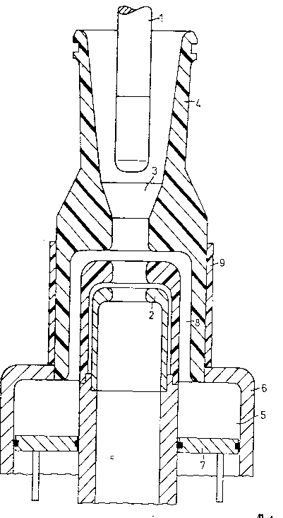
The figure ~rh--~t;cally depicts a circuit breaker with a
nozzle made of insulating material in a longitudinal section
The figure shows a high-voltage circuit breaker having two
contacts 1, 2 arranged rn~ lly opposite one another, of
which the second contact 2 can be driven in a manner not
shown. The circuit breaker is shown in the interrupted state.
In the area of the contact gap 3 between the contacts 1, 2, an
electric arc is drawn during the break procedure that heats up
arc-extinguishing gas present there, particularly SE6 and thus
increases the arc-extinguishing-gas pressure.
The nozzle 4 made of insulating material is securely joined to
the movable contact 2 so that the nozzle moves with it during
the break procedure.
In the area of the contact gap, the nozzle 4 made of
insulating material defines in its interior an electric arc
space, resulting in storage of hot arc-extinguishing gas under
high pressure taking place, that later flows back into the
area of the electric arc during the current zero crossing of
the current to be switched and contributes to extinguishing of
the electric arc or rather a dielectric recovery of the
contact gap 3.
This extinguishing effect is also supported by additional
compressed arc-extinguishing gas that is made available in the
compreseion space 5 by the switching motion between a
compression cylinder 6 and a compression piston 7. The
mechanically compressed arc-extinguishing gas can then flow
via the channel 8 to the contact gap 3.
The nozzle 4 made of insulating material can be produced
advantageously from PTEE (polytetrafluoroethylene) since this
substance releases gases under the influence of an electric
arc that support the extinguishing of the electric arc.
~ N.Cr.ATION - MODIFIED PAOE:

~ 5 9 ~
The nozzle 4 made of insulating material bears on its outside
a plastic tu~e 9 made of fiber-reinforced plastic that is
adhered to the nozzle made of insulating material. The plastic
tube 9 extends over the area of the nozzle 4 made of
insulating material in which it i8 designed with particularly
thin walls.
In this manner, a radial ~Yp~n~; ~n of the nozzle made of
insulating material due to excessive arc-extinguishing-gas
pressure, e.q., due to a high current intensity to be
switched, is avoided.
T~N.~T.~TION - MODIFIFD PAGF

Representative Drawing
A single figure which represents the drawing illustrating the invention.
Administrative Status

2024-08-01:As part of the Next Generation Patents (NGP) transition, the Canadian Patents Database (CPD) now contains a more detailed Event History, which replicates the Event Log of our new back-office solution.

Please note that "Inactive:" events refers to events no longer in use in our new back-office solution.

For a clearer understanding of the status of the application/patent presented on this page, the site Disclaimer , as well as the definitions for Patent , Event History , Maintenance Fee  and Payment History  should be consulted.

Event History

Description Date
Inactive: IPC from MCD 2006-03-12
Application Not Reinstated by Deadline 2005-05-09
Time Limit for Reversal Expired 2005-05-09
Deemed Abandoned - Failure to Respond to Maintenance Fee Notice 2004-05-10
Amendment Received - Voluntary Amendment 2002-08-09
Inactive: Application prosecuted on TS as of Log entry date 2002-05-21
Inactive: Status info is complete as of Log entry date 2002-05-21
Letter Sent 2002-05-21
Request for Examination Requirements Determined Compliant 2002-03-12
All Requirements for Examination Determined Compliant 2002-03-12
Inactive: Adhoc Request Documented 1997-05-08
Deemed Abandoned - Failure to Respond to Maintenance Fee Notice 1997-05-08
Application Published (Open to Public Inspection) 1995-12-07

Abandonment History

Abandonment Date Reason Reinstatement Date
2004-05-10
1997-05-08

Maintenance Fee

The last payment was received on 2003-04-30

Note : If the full payment has not been received on or before the date indicated, a further fee may be required which may be one of the following

  • the reinstatement fee;
  • the late payment fee; or
  • additional fee to reverse deemed expiry.

Please refer to the CIPO Patent Fees web page to see all current fee amounts.

Fee History

Fee Type Anniversary Year Due Date Paid Date
Registration of a document 1997-02-03
MF (application, 3rd anniv.) - standard 03 1998-05-08 1998-04-24
MF (application, 4th anniv.) - standard 04 1999-05-10 1999-04-16
MF (application, 5th anniv.) - standard 05 2000-05-08 2000-04-18
MF (application, 6th anniv.) - standard 06 2001-05-08 2001-04-20
Request for examination - standard 2002-03-12
MF (application, 7th anniv.) - standard 07 2002-05-08 2002-04-30
MF (application, 8th anniv.) - standard 08 2003-05-08 2003-04-30
Owners on Record

Note: Records showing the ownership history in alphabetical order.

Current Owners on Record
SIEMENS AKTIENGESELLSCHAFT
Past Owners on Record
HEINER MARIN
VOLKER LEHMANN
Past Owners that do not appear in the "Owners on Record" listing will appear in other documentation within the application.
Documents

To view selected files, please enter reCAPTCHA code :


To view images, click a link in the Document Description column. To download the documents, select one or more checkboxes in the first column and then click the "Download Selected in PDF format (Zip Archive)" or the "Download Selected as Single PDF" button.

List of published and non-published patent-specific documents on the CPD .

If you have any difficulty accessing content, you can call the Client Service Centre at 1-866-997-1936 or send them an e-mail at CIPO Client Service Centre.


Document
Description 
Date
(yyyy-mm-dd) 
Number of pages   Size of Image (KB) 
Cover Page 1995-05-08 1 18
Description 1995-05-08 6 226
Drawings 1995-05-08 1 23
Abstract 1995-05-08 1 21
Claims 1995-05-08 2 55
Cover Page 1998-06-25 1 18
Reminder - Request for Examination 2002-01-09 1 117
Acknowledgement of Request for Examination 2002-05-21 1 179
Courtesy - Abandonment Letter (Maintenance Fee) 2004-07-05 1 175
PCT 1996-11-28 20 983
Correspondence 1997-01-07 1 48
Fees 1997-04-18 1 61