Note: Descriptions are shown in the official language in which they were submitted.
WO 96130283 ; PCI/US96/04234
2i9161 1
COMPOSll~ PACKAGE FOR SCOOPABLE PRODUCTS
BACKGROUND OF 1~ INVENTION:
This invention relates generally to con~iners for scoopable products and more
particularly, to a novel composite package con~i~ting of an outer paperboard box and
an inner, thin-walled, plastic jar ~uppGlled within the box and especially dç~i~ned
for holding scoopable products such as marg~ine, shortening, pickles and potato
salad, bird seed, pet food, cat litter, pool çhtomic~l~, and the like.
Scoopable products such as ",~;~ine and shortening are most commonly
supplied to the commercial food industry in large rigid plastic pails or buckets of
about two to six gallons in size. The pails are usually circular in cross section,
slightly tapered inwardly from top to bottom to accommodate the injection molding
process by which they are normally produced. The pails usually have a large opentop sealed by a removable lid.
Although these type pails have found wide use in commercial and industrial
applications, they do suffer from a number of disadvantages. Rec~uce of the
sul,s~tial wall thickness of the plastic m~tçri~l, the price of the pails is very high.
Also adding to the overall cost of using those type pails is the inefficient space
utilization of the pails during shipping, h~nrlling, and storage because of their round
and tapered shape. Further, the lids placed on the open top of the pails are often
difficult to apply and remove, som~timeS requiring a rubber mallet to beat the top
on, and a pry bar of some type to remove the top. Additionally, the pails are
difficult to dispose of and have been known to present a drowning hazard to small
children should they become filled with water.
Another type of container which has been suggested for use with scoopable
products is a "bag-in-box" which includes an outer paperboard box lined with an
inner, flexible, plastic bag. This type of container also suffers several disadvantages.
For example, the bag and the box are normally shipped to a customer as sepal~te
components and they must be assembled together by the customer before the package
W 0 96/30283 2 1 9 1 6 1 1 . PC~rrUS96/04234
is filled. Further, the bag itself or the bag in the box has no convenient resç~ling
system, which creates problems once the bag is opened. Also, the products in thecont~iner, for example, ."~gdline or shortening, can be trapped in the folds or
wrinkles of the bag and scraping the sides of the bag to try to scoop out all of the
product can cause the bag to shift, collapse, or rupture, none of which is desirabl.
Thus, a need exists for a lower-cost, space-saving, easier-h~ndling package
for holding scoopable products. Applicant and the ~ignee of this application aref~ mili~r with prior art composite packages con~i~ting of a thin-walled plastic bottle
in an outer paperboard box for holding pourable liquid products, with the top of the
bottle provided with a small spout through which the liquid may be poured from the
bottle and an integrally molded handle for holding the package during the pouring
operation. However, prior to this invention, those types of composite packages have
not been known for use with scoopable products.
SUMMARY OF THE INVENTION:
Accordingly, the primary object of this invention is to provide a novel,
co~"posite package comprising a large mouth, thin-walled, lightweight, blown plastic
jar in an outer paperboard box suitable for holding scoopable products such as
~,.ar~ e, shortening, or the like.
Another object of the invention is to provide the above-described novel
composite package wherein the plastic jar acts as a smooth, self-~uppolling, inner
liner with a large top opening for holding the scoopable products and the outer
paperboard box acts as a strong outer shell for shipping, stacking, and h~n~ling~ul~oses. After filling, the large open mouth of the jar is sealed with a snap-on or
thread-on plastic lid and the paperboard box has an upper flap assembly which isclosed and sealed to protect the inner jar during shipping and storage. A tear strip
exten-ling around the box just below the upper flap assembly enables the end user
to quickly remove the flap assembly and gain access to the lid on the jar.
Still another object of the invention is to provide the above, novel, composite
package in which the plastic jar is subs~nti~lly square and fits closely within a
subst~nti~lly square paperboard box to not only maximize the storage capacity of the
3 ~ql~
package, but also to utilize most efficiently the shipping and st~çking space on a
standard 40" x 48" grocery pallet.
A further object of the invention is to provide the above novel composite
package in which the thin walled plastic jar is easily crushed to facilitate its disposal
and avoid any safety hazards. Similarly, the outer paperboard box can be quicklyflattened and recycled in existing municipal recycling systems.
Other objects and advantages of the invention will become apparent
from reading the detailed description of the invention in which reference is made to
the accompan~ing drawings where like numerals indicate like elements.
Therefore, in accordance with the present invention, there is provided a
composite package comprising an outer rectangular paperboard box having verticalfront, rear, and side walls and an upper foldable flap assembly connected to said
vertical walls, a~ inner thin-walled plastic jar having a lower generally rect7~n~~ r
portion fitting within said box and an upper portion of slightly reduced cross-sectional
size provided with a large open mouth, a lid removably connected over said mouth,
said lid being separate from but normally covered by said flap assembly, said upper
portion having wall sections spaced inwardly from opposed walls of said box to
provide finger receiving spaces therebetween, said opposed walls having finger
receiving openings adjacent said spaces to facilitate h~n(lling of said box, means
perrnittin~ complete removal of said upper flap assembly from said walls to provide
access to said lid, said removal means being located between said upper flap assembly
and said finger receiving openings.
Also, in accordance with the present invention, there is provided a
composite p~ekage for use with scoopable products comprising an outer rect~n~ r
paperboard box having vertical front, rear, and side walls and an upper foldable flap
assembly connected to said vertical walls, an inner thin-walled plastic jar having a
lower generally rectangular portion fitting within said box, an upper portion of slightly
reduced cross-sec~ional size provided with a large circular open mouth subst~nt~ y
concentric with said lower rect~n~ r portion through which a scoop may pass to
remove product from within said jar, and a smooth contoured transitional sectionext~n~ing between said lower rect~n~ r portion and said upper portion, a lid
removably connected over said mouth, said lid being separate from but normally
covered by s~id flap assembly, said transitional section having wall sections spaced
inwardly from opposed walls of said box to provide finger receiving spaces
therebetween, said opposed walls having finger receiving openings adjacent said
spaces to facilitate handling of said box.
A
3a
BRIEF DESCRIPTION OF THE DRAWlNGS:
Figure 1 is a fragmented generally perspective view of the novel
composite package of the invention.
Figure 2 is a fragmented sectional view taken generally along the line
2-2 of Figure 1.
Figure 3 is a generally exploded perspective view of the composite
package of the invention illustrating the lid of the jar and the top flap assembly of the
paperboard box in their removed positions.
DETAILED DESCRIPTION OF THE INVENTION:
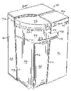
Ret'erring now to the drawings, the composite package 10 of the
invention includes a substantially square outer corrugated paperboard box 12 and a
subst~nti~lly squa~e inner large mouth lightweight thin-walled but self-supporting
plastic jar 14 fitting closely within paperboard box 12.
Box 12 includes vertical front and rear walls 16 and 18, respectively,
side walls 20 and 22, a bottom flap assembly 24, and a top flap assembly 26.
The thin-walled plastic jar 14 is m~nllf~ctured by a blow-molded
process and includes a substantially square lower portion 29 having opposed front and
rear walls 30 and 32, opposed side walls 34 joined with walls 30 and 32 at largeradiused
'~
WO 96/30283 2 1- 9 1 6 1 1 PCT/US96/04234
corners 36, and a bottom wall 38 joining the vertical walls at a large radiused corner
40. The wall thi~ cc of the jar is about .025 inches.
As seen in the drawings, the upper end 42 of bottle 14 is circular in cross-
section, and the change from the square cross-section of lower portion 29 is
accomplished by the contoured transitional area 44 exte-n-ling between square portion
29 and circular section 42. Transition area 44 includes inwardly radiused sections
46 and 48 which join curved vertical wall sections 50 and 52 that are spaced
inwardly from box walls 16 and 18 to provide ample finger receiving clearance
spaces 54 and 56 belween sections 50 and 52 and walls 16 and 18. Walls 16 and 18are provided with finger receiving die-cut slots 58 and 60 by which the composite
package may be gripped for moving and handling purposes.
Sections 62 of transitional area 44 which extend between side walls 34 and
circular section 42 generally taper upwardly inwardly and blend smoothly with
sections 50 and 52.
Section 42 is provided with a plurality of intellupted circular reinforcing ribs66 spaced beneath its large circular open mouth 68 defined by a continuous circular
flange 70, over which a snap-on lid 72 may be quickly placed or removed to seal or
provide access to the content~ of jar 14. The size of section 42 and mouth 68 are
made as large as possible with respect to the top opening of box 12 so that the end
user can quickly and easily scoop virtually all of the contents out of jar 14. The
upper end of jar 14 is slightly reduced in size only a sufficie-nt amount to provide
finger clearance spaces 54 and 56 and to provide suffiçient clearance for application
and removal of the snap-on lid 72.
In assembling the composite package, box 12 is set up from a flat,
paperboard blank and the bottom flap assembly 24 is glued together. A plastic jar
14 is then inserted into box 12 with the lid 72 removed. The jar is then filled with
l,.a.~ine or the like, and the lid 72 is snapped in place. The upper foldable flap
assembly 26 is then glued down and the filled package 10 is shipped to an end user.
To facilit~te use by the end user, box 12 is provided with a tear strip 76 extending
around the periphery of its side walls at a point below lid 72 to provide for complete
removal of upper flap assembly 26 and afford ready and convenient access to lid 72.
WO96/30283 2 1 9 1 6 1 1 PCT/US96/04234
For sizes up to five gallons, the composite package 10 is of subst~nti~lly
square ~lim~ncionC~ for example, 9.7" x 9.4" footprint, which adapts conveniently
to a convention~l 40" x 48" pallet and pallet utili7~tion has been found to be
approximately 95% effit~i~nt For sizes five gallons and larger, the footprint may
be 9.7" x 11.7" to make the pallet more stable while still efficiently utili7ing pallet
space. The size of the package 10 can be readily varied because the inner jar ismanufactured by a blow molding process, and for each footprint, a single
inexpensive mold can produce all of the required sizes or anything in between bysimply adding or removing height segm~ntc from a central section of the mold~
While the lid 72 has been described as a circular snap-on type, it may be
~ecign~d as a square snap-on type, or as a circular screw-on lid. Similarly, for some
applications, box 12 may be provided with a carrying handle or strap instead of die
cut openings 58 and 60.
Numerous advantages of the co-.-posile package 10 of the invention are
readily appalt;nt from the description above. The mouth 68 is very large, and the
interior surfaces of jar 14 are very smooth to enable an end user to easily scoop
virtually all of the conten~ out of the jar. The large radiuses 36 and 40 and the
smooth contoured transition section 44 make for easy filling, scooping, and scraping
of the contents from the jar. In addition, the package 10 can be offered in a variety
of sizes and with a variety of lid types to suit a particular application. The package
10 is very light, and less expensive than the conventional heavy-walled pails. After
use, the outer box 12 can be easily fl~tt~ned and recycled and the inner thin-walled
plastic jar 14 is easily crushed and disposed of. Furthermore, after the jar 14 is
filled and sealed with lid 72 and the flap assembly 26 is glued down in place, the
closed flap assembly keeps dust, dirt, rodents, etc. away from jar 14 during shipping
and storage of package 10. Hence, when flap assembly 26 is removed by pulling
on tear strip 76, the lid 72 and jar 14 are clean and ready for use.
The invention may be embodied in other specific forms w;thout
departing from the spirit or essential characteristics thereof. The present
embodim~ntc are therefore to be considered in all respects as illustrative and not
restrictive, the scope of the invention being indicated by the appended claims rather
w096/30283 2 1 9 1 6 1 1 ~cr/US96104234
than by the fof~go~lg de~ ion, and all changes which come within the mt~ning
and range of equivalency of the claims are therefore intended to be embraced
therein.