Language selection

Search

Patent 2191727 Summary

Third-party information liability

Some of the information on this Web page has been provided by external sources. The Government of Canada is not responsible for the accuracy, reliability or currency of the information supplied by external sources. Users wishing to rely upon this information should consult directly with the source of the information. Content provided by external sources is not subject to official languages, privacy and accessibility requirements.

Claims and Abstract availability

Any discrepancies in the text and image of the Claims and Abstract are due to differing posting times. Text of the Claims and Abstract are posted:

  • At the time the application is open to public inspection;
  • At the time of issue of the patent (grant).
(12) Patent Application: (11) CA 2191727
(54) English Title: AIR VENT DEVICE INCLUDING A LIGHT DEVICE TO PREHEAT SUPPLY AIR
(54) French Title: DISPOSITIF D'AERATION
Status: Deemed Abandoned and Beyond the Period of Reinstatement - Pending Response to Notice of Disregarded Communication
Bibliographic Data
(51) International Patent Classification (IPC):
  • F24F 13/078 (2006.01)
  • F24F 3/056 (2006.01)
  • F24H 3/00 (2006.01)
  • H05B 3/00 (2006.01)
(72) Inventors :
  • VÝLSTAD, OVE CHARLES (Norway)
(73) Owners :
  • LEGABEAM NORGE AS
(71) Applicants :
  • LEGABEAM NORGE AS (Norway)
(74) Agent: NORTON ROSE FULBRIGHT CANADA LLP/S.E.N.C.R.L., S.R.L.
(74) Associate agent:
(45) Issued:
(86) PCT Filing Date: 1995-05-31
(87) Open to Public Inspection: 1995-12-14
Availability of licence: N/A
Dedicated to the Public: N/A
(25) Language of filing: English

Patent Cooperation Treaty (PCT): Yes
(86) PCT Filing Number: PCT/NO1995/000087
(87) International Publication Number: WO 1995033959
(85) National Entry: 1996-11-29

(30) Application Priority Data:
Application No. Country/Territory Date
942042 (Norway) 1994-06-02

Abstracts

English Abstract


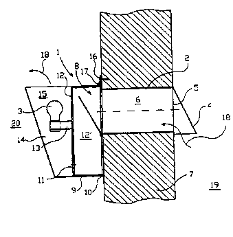
A device for an air valve, particularly for use with a fresh air inlet through
a wall (7) in living rooms (20), and wherein the device (1) comprises a
receiver (9) preferably consisting of metal, plastic or another air-tight
material, and wherein the receiver (9) is adapted to be tightly attached to
the wall (7) around the internal valve opening (8), and wherein the receiver
(9) is divided into an outer room (12') and an inner room (15), a connection
(11) being established between the rooms (12', 15). To the receiver (9) is
attached a bulb holder (13) having a supply of electrical current for a bulb
(3), so that the fresh air stream flows past the bulb (3) and receives heat
therefrom before it leaves the receiver (9) and escapes into the living room
(20).


French Abstract

Dispositif pour clapet d'admission d'air particulièrement destiné à être utilisé avec une admission d'air neuf prévue dans un mur (7) de pièce d'habitation. Ledit dispositif (1) comporte un collecteur (9) de préférence en métal, plastique ou tout autre matériau étanche à l'air et conçu pour être fixé de manière hermétique sur le mur (7), autour de l'ouverture de la soupape interne (8). Ledit collecteur (9) est divisé en une chambre externe (12') et une chambre interne (15) reliées entre elles par un raccordement (11). Une douille d'ampoule (13) dotée d'une source d'alimentation électrique pour ampoule (3) est fixée au collecteur (9) de sorte que le flux d'air neuf s'écoule au-delà de l'ampoule (3) et bénéficie de la chaleur dégagée par cette dernière avant de sortir du collecteur (9) et de s'échapper dans la pièce d'habitation (20).

Claims

Note: Claims are shown in the official language in which they were submitted.

C l a i m s
1. A device for an air valve, particularly for use with a
fresh air inlet through a wall (7) in living rooms, and
wherein the device (1) comprises a receiver (9) preferably
consisting of metal, plastic or another air-tight material,
and wherein the receiver (9) is adapted to be attached
tightly to the wall (7) around the internal valve opening
(8), and wherein the receiver (9) is divided into an outer
chamber (12') and an inner chamber (15), a connection (11)
between the chambers (12', 15) being established, said
device (1) cooperating with at least one heating means,
causing preheating of the fresh air before it flows into said
living room, c h a r a c t e r i z e d i n that said at
least one heating means is constituted by at least one
electrical bulb (3), bulb holder means (13) having electrical
current supply for said electrical bulb(s) (3) being attached
to the receiver (9), so that the fresh air stream flowing
unforcedly past the bulb(s) (3), receiving heat therefrom
before leaving the receiver (9), preferably uppermost in
the inner chamber (15).
2. A device as set forth in claim 1,
c h a r a c t e r i z e d i n that the outer chamber (12')
communicates with more than one inner chamber (15), each of
which containing an electrical bulb (3).

Description

Note: Descriptions are shown in the official language in which they were submitted.


~ W095/33959 2191 727 rcl".~s~
~1r vent device including a light device to preheat supply
air.
The present invention relates to a device for an air valve,
pcperiAlly for use at a fresh air inlet through a wall of a
livinq room, and wherein the device comprises an ~ ting
vat or receiver which preferably consists of metal, plastic
or another air-tight material, and wherein the ~ lAting
vat is adapted to be attached tightly to the wall around the
internal valve opening, and wherein the n~ lAting vat is
divided into an external room and an internal room,
connection between the rooms being established.
~odern house building methods re~uire to a very large extent
the use of vapour barriers, such as plastic foils and the
like, inside the walls. This results in too tight buildings.
This is unfortunate in houses, flats and cottages lacking
~-~h~nicAl ventilation. The same applies also to rooms
in which many people are gathered, e.g. class rooms and
the like, and in older b~ ;ngc lacking r- '-ni~l
ventilation plant. Even in bl~ i ng5 in which mechanical
ventilation has been mounted, the b~ ingc become too
tight, because the -- -";c~l ventilation plant is
sometimes closed, or when the same does not funtion
according to the ~-~au~yOSitiOn.
Fcpt~c;~lly in living rooms or other places where there exists
a requirement for sound reduction, a -n;cAl ventilation
plant is often less favourable, not least because of the
SUBSTITUTE SHEET

WO 95l33959 r~ o
~1917~7 '
noice.
More recently it has also been ascertained that ordinary
ventilation plants ln themselves L~Lu~.L a not
~ n c~ ~n ~ f ~r~nt pollution source.
Houses and flats are usually equipped with fresh alr
valves in windows or have fresh air inlets mounted at a high
level in the outer walls. This functions as an air supply in
the warm part of the year. In winter time or other times of
the year where outdoor t , ~Lu,~s are relatively low, the
1nfl~ -ing air seems dL~uyllLy and cold. I most cases, this
results in a closing of the valve. The ~a~ is that
the house does not "breath" such as required by modern
b~ i ng methods in order to be wa~ L~ble.
When the house becomes too tight, this gives i.a. favourable
conditions for the growth of mould/humidity, dev~l , L of
micro organisms, bacteria and virus. In its turn, this is
a contributory factor to growth of allergy and asthmatic
sufferings. This is a very serious and growing problem
in all countries in which b~ ;n5 is ~ulldu~L~d according to
moderne pr~ n~i rl RS .
UI~uLLu,laLuly, closed valves are common, resulting in -
without the inhabitants in many cases being aware thereof -
that modern houses some times may be directly in~urious to
health.
From NO patent No. 63925, it is previously known an
r -r--~ L in an air valve for use with a fresh air inlet
throu~h a wall of a living room where the air valve is placed
ad~acent the floor, outside a radiator for heating the living
room, and where the device comprises an r 1 ~ting vat or
receiver adapted to be tightly ~LL~.l-ed to the wall around
the internal valve opening, and wherein the 7 l~ting vat
is divided into an outer room and an inner room, a la
connection being est~hl ~ ch~d between the rooms, and wherein
SUBSTITUTE SHEET
_ _ . .. .. ... _ ..... ..... . . _ _ _ _ _ _ _ _ _

W0 951339S9 ~19 ~ 7 2
the inner room is very narrow and positioned close to the
radiator, so that the fresh air flowing through the two rooms
of the r llting vat i9 S~rrli~d with heat from the
radiator, before it flows out into the living room through
an ~ L slot in the inner room of the r llting vat
or receiver.
Two large di~dv~l-L~yes ol the device according to N0 No.
63925 are 1) that the device is ~ L on a radiator, 2)
that the device is ~ L on that the air valve in the
wall is positioned adiacent the Cloor where the radiator i9
located, air valves usually being placed high up on the
wall. This means that existing air inlet cannot be used
wlth the device, and that a new hole must be bored or drilled
in the wall for a new air valve to be used in connection with
said device.
From N0 patent No. 56816 and N0 patent No. 57180, LL o Lo
in air valves o~ similar klnd as the above ~o~r~ hed device
rccording to N0 patent No.-63925 have been previously known,
but these devices also su~fer from the same two large
disadv~-L~yes 1) and 2) as mentioned above.
In a~uuLd~ ~e with the present invention, one aims at a
very simple device, ser~ ns an ~ff~r~nt air supply,
simultaneously as one achieves a pleasant ba~kyLuuld
~1 'n~tion to the room to be ventilated, the device
comprising a usual bulb by which the air s~rpl~ becomes
pleasintly heated, even during the most e~LL ly low
outdoor i ~LuLes to be found, ln that the air passes the
bulb. This results in that the air s~rrl~ed is felt as being
pleasant, as it is ~LeheuLed by means of the bulb to above
room i ~LuLe be~ore it is let in.
In order to utilize the invention, existing valves in
outer walls can be used. Without making any e..~L.
in the existing valve ~LL_, L, the device according to
the invention is mounted on the inner side of the wall.
SUBSTITUTE SHEET

Woss/33959 ~ ~ g t ~ ~ 7 P~ 5 ~ / ~
When placing the valve in an open condition, simultlnaoncly
as the bulb is switched on, ~LeheaLed fresh air will flow ln
in a pleasant way. In other words, one achieves the same
effect as with a conventional expensive ventilation plant
blowins in uL~he~L_d fresh air. Additionally, a pleasant
ba~L~,u~,d ill 'nntion of the actual living room is
achieved.
Because of its ci lanacs, the device according to the
invention will be very cheap. The installations do not in any
way require expert knowledge, as it does not involve any
uu--~LLu~Llonal works, and the device is not ~Pp~ L on a
radiator.
In the following, two ~L~L~LL~d ~-~i L~ of the device
r~ ~ ng to the invention are ~acrri ha~, L ~ r~ ae being
~ade to the ; - ying drawings, wherein:
Figure 1 shows a vertical section of the device, showing the
, L~ in~uLuoL~L~d in the device according to the
invention;
Figure 2 shows a front view of the device accordins to figure
l;
Figure 3 shows a plan viewjhorizontal section of the device
according to figure 1.
In the drawings, L~L~L~ ~e numeral 1 denotes the dèvice
accoraing to the invention in general, the same being
in~ a~ in a oul-~LLuuLlon comprising a usual air valve 2
in a wall 7 and a bulb 3, these ~ L~ being
i-lLu uu,~ e~Led to form a unit. ~he device 1 is a ~uh~LellL
unit coupled to the air valve 2, which ~LuL~L~bly and usually
sits in the ,~ L portion of the wall 7.
~he air valve 2 consists ordinarily of an external storm cap
~, an insect net 5, a channel 6 through the wall 7 and an
SU5STIT:JTE SI~EET

~ W095l339s9 21917 2 7 r~
air inlet 8 at the inner side of the wall. The air valve 2
as described above is not critical and may, therefore, have
any design as usually installed in hn i 1 r7 i ngc .
In one ~mho~7; L, the device 1 comprises an acc~ ting
vat or receiver 9 which is u ~7- ~a~e-insulated, and which
~U~LUUIIdS the whole air inlet 8 of the valve 2. The
A~ l~ting vat or receiver 9 is, as shown in the drawings,
somewhat larger than the air inlet 8, and against the wall
sealed with a fl~Y;hl~ rubber packer 10. In the 1: - L
portion of the collecting box 9, a hole 11 has been formed in
an inner partition wall 12 parallel to the wall 7. At the
partition wall 12, an outer room lZ' is formed between the
partition wall and the wall 7. A carrier 13 into which the
bulb is screwed, is fastened to the partition wall 12 and
is lur-uu--ded by a lamp-shade 14 preferably made of metal,
plastic or other air-tight material, and which forms an inner
room 15 together with the partition wall 12. The device 1 is
~ .5~d from the wall by means of a anchoring point 16,
through an attaching means 17.
When the device 1 is interconnected with the air valve 2
such as described, and the bulb 3 has been switched on,
outdoor air 18 will be conducted from the outside of the wall
through the channel 6 through the wall 7 and into the
receiver's 9 room 12', from where it continues into the room
15 through the channel 11 of the partition wall 12,
whereafter it becomes heated by the bulb 3 to preheated fresh
air which, then, flows into the living room 20. Additionally,
one gets illllm;nltion from the bulb 3 into the room 20,
possibly in the form of an indirect i~ m;n~tion if the
lamp-shade 14 has been made of opaque material, and a
combination of direct and indirect ;11 nm; n~tion if the
lamp-shade 14 has been made of transparent material.
In the other ~ , the device 1 consists of the same
Ls as described in the first ~mho~7i L, with the
eYception that the a~ lating vat (receiver, collecting
SUBSTITUTE SHEET

W095/33959 2191~27 rc~ 9~ , ~
box) 9 constitutes a horizontal, relatively long channel
coupled to the air valve 2 in a central point on the
a_ lAting vat 9. To the relatively long a l~ting box 9
is uu,~-auL~d several sapo-OLe carriers 13 for bulbs 3, which
are ~uL~u~-ded by lamp-shades 14, the bulbs 3 being ~u-~la~L~d
in series.
In the second ~ L, the same effect as described in
connection with the first -'i L is achieved, the
difference consisting in the use of more bulbs 3 and
lamp-shades 14 in the second : '~ L, meaning a larger
mount of light and larger capacity of 5~pp~ preheated
fresh air to the living room 20.
SUBSTITUTE SHEET

Representative Drawing
A single figure which represents the drawing illustrating the invention.
Administrative Status

2024-08-01:As part of the Next Generation Patents (NGP) transition, the Canadian Patents Database (CPD) now contains a more detailed Event History, which replicates the Event Log of our new back-office solution.

Please note that "Inactive:" events refers to events no longer in use in our new back-office solution.

For a clearer understanding of the status of the application/patent presented on this page, the site Disclaimer , as well as the definitions for Patent , Event History , Maintenance Fee  and Payment History  should be consulted.

Event History

Description Date
Inactive: IPC expired 2022-01-01
Inactive: IPC from MCD 2006-03-12
Time Limit for Reversal Expired 2003-06-02
Application Not Reinstated by Deadline 2003-06-02
Deemed Abandoned - Failure to Respond to Maintenance Fee Notice 2002-05-31
Inactive: Abandon-RFE+Late fee unpaid-Correspondence sent 2002-05-31
Application Published (Open to Public Inspection) 1995-12-14

Abandonment History

Abandonment Date Reason Reinstatement Date
2002-05-31

Maintenance Fee

The last payment was received on 2001-05-24

Note : If the full payment has not been received on or before the date indicated, a further fee may be required which may be one of the following

  • the reinstatement fee;
  • the late payment fee; or
  • additional fee to reverse deemed expiry.

Please refer to the CIPO Patent Fees web page to see all current fee amounts.

Fee History

Fee Type Anniversary Year Due Date Paid Date
MF (application, 3rd anniv.) - small 03 1998-06-01 1998-05-20
MF (application, 4th anniv.) - small 04 1999-05-31 1999-05-25
MF (application, 5th anniv.) - small 05 2000-05-31 2000-04-18
MF (application, 6th anniv.) - small 06 2001-05-31 2001-05-24
Owners on Record

Note: Records showing the ownership history in alphabetical order.

Current Owners on Record
LEGABEAM NORGE AS
Past Owners on Record
OVE CHARLES VÝLSTAD
Past Owners that do not appear in the "Owners on Record" listing will appear in other documentation within the application.
Documents

To view selected files, please enter reCAPTCHA code :


To view images, click a link in the Document Description column. To download the documents, select one or more checkboxes in the first column and then click the "Download Selected in PDF format (Zip Archive)" or the "Download Selected as Single PDF" button.

List of published and non-published patent-specific documents on the CPD .

If you have any difficulty accessing content, you can call the Client Service Centre at 1-866-997-1936 or send them an e-mail at CIPO Client Service Centre.


Document
Description 
Date
(yyyy-mm-dd) 
Number of pages   Size of Image (KB) 
Representative drawing 1997-12-05 1 13
Claims 1995-12-14 1 35
Drawings 1995-12-14 2 46
Cover Page 1998-06-25 1 15
Description 1995-12-14 6 233
Abstract 1995-12-14 1 57
Cover Page 1997-05-12 1 15
Reminder - Request for Examination 2002-02-04 1 117
Courtesy - Abandonment Letter (Maintenance Fee) 2002-07-02 1 183
Courtesy - Abandonment Letter (Request for Examination) 2002-07-15 1 170
Fees 1996-11-29 1 57
International preliminary examination report 1996-11-29 8 271