Language selection

Search

Patent 2191760 Summary

Third-party information liability

Some of the information on this Web page has been provided by external sources. The Government of Canada is not responsible for the accuracy, reliability or currency of the information supplied by external sources. Users wishing to rely upon this information should consult directly with the source of the information. Content provided by external sources is not subject to official languages, privacy and accessibility requirements.

Claims and Abstract availability

Any discrepancies in the text and image of the Claims and Abstract are due to differing posting times. Text of the Claims and Abstract are posted:

  • At the time the application is open to public inspection;
  • At the time of issue of the patent (grant).
(12) Patent Application: (11) CA 2191760
(54) English Title: TUBEFORMED ROCK BOLT
(54) French Title: BOULON D'ANCRAGE TUBULAIRE
Status: Deemed Abandoned and Beyond the Period of Reinstatement - Pending Response to Notice of Disregarded Communication
Bibliographic Data
(51) International Patent Classification (IPC):
  • E21D 20/00 (2006.01)
  • E21D 20/02 (2006.01)
  • E21D 21/00 (2006.01)
(72) Inventors :
  • KAREBY, BJORN (Sweden)
  • MANDAL, ANITA (Sweden)
(73) Owners :
  • ATLAS COPCO ROCK DRILLS AB
(71) Applicants :
  • ATLAS COPCO ROCK DRILLS AB (Sweden)
(74) Agent: SMART & BIGGAR LP
(74) Associate agent:
(45) Issued:
(86) PCT Filing Date: 1995-06-01
(87) Open to Public Inspection: 1995-12-14
Availability of licence: N/A
Dedicated to the Public: N/A
(25) Language of filing: English

Patent Cooperation Treaty (PCT): Yes
(86) PCT Filing Number: PCT/SE1995/000608
(87) International Publication Number: SE1995000608
(85) National Entry: 1996-11-29

(30) Application Priority Data:
Application No. Country/Territory Date
9401894-2 (Sweden) 1994-06-02

Abstracts

English Abstract


Tubeformed rock bolt with closed cross section. The rock bolt comprises a tube
(11) provided with a longitudinal depression (12). The tube is at the ends
provided with a first sleeve (14) and a second sleeve (13). The sleeves are
welded to the tube (11) so that a closed room (23) is created. The second
sleeve (13) is provided with a radial groove (20) for giving the rock bolt a
predetermined angular position in a tool used for setting the bolt and a first
hole (18) for injection of cement. The tube (11) is furthermore provided with
a second hole (19) near a first end (21). This hole is a venting hole for the
closed room (23).


French Abstract

Boulon d'ancrage tubulaire de section fermée. Ce boulon d'ancrage comprend un tube (11) pourvu d'une dépression longitudinale (12), et, à ses extrémités, d'un premier (14) et d'un second (13) manchon. Ces manchons sont soudés au tube (11) de façon à créer une chambre fermée (23). Le second manchon (13) est doté d'une rainure radiale (20), permettant au boulon d'ancrage d'adopter une position angulaire prédéterminée dans un outil utilisé pour placer le boulon, ainsi que d'un premier trou (18) destiné à l'injection du ciment. Le tube (11) est en outre doté d'un second trou (19), à proximité d'une première extrémité (21), qui agit comme trou d'évacuation d'air de la chambre fermée (23).

Claims

Note: Claims are shown in the official language in which they were submitted.

Claims:
1 Tubeformed rock bolt with closed cross section comprising a tube (11)
provided with a longitudinal depression (12) along at least a part of its length, a first
sleeve (14) surrounding the tube at a first end (21) of the tube. a second sleeve (13)
surrounding the tube at a second end (22) of the tube and a first hole (18) through
said second sleeve (13) and said tube (11) for connecting a closed room (23),
confined by the rock bolt with the surroundings, c h a r a c t e r i z e d in that the
rock bolt near the second end (22) of the tube (11) is provided with orientation means
(20) gor giving the rock bolt a predetermined angular position in a tool and that the
rock bolt near the first end (21) of the tube (11) is provided with a second hole (19)
which connects said closed room (23) with the surroundings.
2. Tubeformed rock bolt according to claim 1. c h a r a c t e r i z e d in
that said orientation means is a radial groove (20) in the second end (22) of the rock
bolt.

Description

Note: Descriptions are shown in the official language in which they were submitted.


wo gs/339i6 ~ :~ ; b2 1 ~ ~ 7 ~ ~ PCTISE~/00608
Tubeformed rock bolt
The present invention relates to a LuiJ~.I'u~ cd rock bolt ~ ~th closed cross section. The
rock bolt according to the invention is intended to be expanded into contact with the
rock by means of cement or other cull~,u~ viscous material.
It has for a lone time been a desire to expand tllhPfnrtnP-1 rock bolts with cement in
order to achieve a bolt which can stand higher shearing forces. With a prior artLul,.~u.,l..d rock bolt. see US 4 423 986~ it has turned out to be difficult to use
cement fûr expansion of the bolt since one gets cement about the bolt end so that
difficuities arise when taking away the setting tool after the bolt has been set.
F~llLLI,illlUIe. one has obtained an entrapped air volume which after the bolt has been
set hns pressed out a part of the cement uhich was used at the expansion of the bolt.
The present invention, which is defined in the appended claims. aims at solving the
above mentioned problems by forming the rock bolt so that one avoids that the
cement ~ i ' about the bolt end and by seeing to it that the cement is not
pressed out from the rock bolt when it is set.
A further advantage with the present invention is that the protection against corrosion
of the bolt is improved because cement during expansion of the bolt forces its way
out through a venting hole near the end of the rock bolt being innermost in the bore
hole so that a plug of cement is created about the top of the bolt. This ~ u~
decreases. or prevents, the amount of water that trickles along the outside of the bolt.
An ~"3,o~1",. .~ of the invention is described beiow with reference to the
a..~,ullltJ~~ 3 drawings in which fig I shows a Lub.,fu~ .,1 rock bolt according to the
invention. Fig 2 shows a section according to 2-2 in fig 1. Fig 3 shows a section
through the rock bolL after expansion in a bore hole. Fig 4 shows a section through a
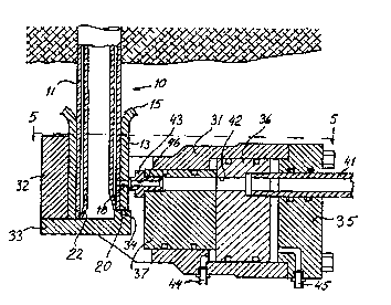
part of the rock bolt and a part of a tool for setting the bolt. Fig ~ is a view according
to 5-5 in fig 4. Fig 6 shows shows the ~u..l,~" I;..u between the tool and the rock bolt
during expansion of the rock bolt. Fig 7 shous ~.m-pP~ti-m between tool and rock bolt
after the expansion of the rock bolt has been finished.

wo gs~33gl6 ~ ~ 2 i ~
The tubeformed roch bolt 10 shown in figs 1-3 comprises a tube 11 which in the
u~ ul'~ g has been provided with a l.~ depression 12 along a part of its
length. preferably along all the len~th. The bolt has a first end 21 which is surrounded
by a first sleeve 14 and a second end 22 which is surrounded by a second sleeve 13.
The sleeves 13 and 14 are welded to the tube 11 so that an enclosed room 23 is
created. A hole 18 connecting the room 23 with the ~ul~uullJhl~5a extends through the
second sleeve 13 and the tube 11. The tube 11 is I~UIIh~ IUIC; provided with a second
hole 19 near the t;rst end 21 of the tube 11. This hole~ which is a venting hole for
lening our air trom the room 23 when the bolt is expanded~ is suitablv arranged in the
tube 11 at some distance from the sleeve 14. The sleeve 13 is provided with a flange
I j which forms a support for a washer 16 which is intended for contacting the rock
when the boit has been set. The washer 16 is provided with a hole 17 which has alarger diameter than the sleeve 14 but a smaller diameter than the flange 15 so that
the washer can be mounted on the bolt before the setting of the bolt. The sleeve 13 is
provided with orientation means in form of a radial groove 20 by means of which the
rock bolt is given a defined angular position in a tool for setting the bolt.
The tool shown in figs 4-7 for setting the rock bolt 10 comprises a housing 31
provided with a cover 35 screwed to the housing. The housing 31 comprises a dolly
32 against which the rock bolt 10 can be pressed. The dolly 32 is provided with a
support 33 for the rock bolt. The support 33 is pro-ided with a projection 34 for
COO~ ;U~I with the groove 20 in the sleeve 13 on the rock bolt. Two pistons 36 and
37 are slidably arranged in the housing 31. The pistons are in a suitable way
connected with each other and can of course be made in one piece.A channel 42
extends through the pistons. A tube 41 for supply of cement is connected to the
channel 42. In the other end of the channel 42 a nozle 43 is arranged. The no77ie 43
is provided with a channel 46 and a hardened sharp edge 51. The pistons 36. 37 are
moved in the housing 31 by suppl~ying pressure liquid through one of the .. ".. ~ ti
44. 45.
A rock bolt according to the invention is set in the following way. A bolt 10 is placed
on the support 33 and turned so that the projection 34 fits into the groove 20. through
which the angular position of the bolt is dei;ned relative to the support 33. After this

2 i 9 1 ~0
WO 95f33916 ~ p "~
pressure liquiL e.g. hydraulic oil. is supplied through conneclion ~. The pressure is
then of the order of 80 bar. The sharp edge 51 enters into the sleeve 13 as sho~n in
fig 6 so that a seal is obtained around the hole 18. After this the bolt is e.xpanded with
cement which is supplied via the channel 46 and the hole 18. During the eYpansion
the boit is vented through the hole 19 so that no air cushion is created in the bolt. The
supply ol cement suitably continues until a plug of cement has been created about the
end 21 of the bolt.lt is ad~ t..~ ua to use a cement which after injection, during the
setting, s~vells. After the e~pansion the pressure in the connection 45 is increased to
about 00 bar. I'he sharp edge jl penetrates deeper into the sleeve 13 as shown in fig
7. Through this the hole 18 is closed so that cement does not flow out of the bolt. The
pistons 36. 37 are then moved to the right in fig 4 through ~ aau~i~hl~g the connection
44.

Representative Drawing
A single figure which represents the drawing illustrating the invention.
Administrative Status

2024-08-01:As part of the Next Generation Patents (NGP) transition, the Canadian Patents Database (CPD) now contains a more detailed Event History, which replicates the Event Log of our new back-office solution.

Please note that "Inactive:" events refers to events no longer in use in our new back-office solution.

For a clearer understanding of the status of the application/patent presented on this page, the site Disclaimer , as well as the definitions for Patent , Event History , Maintenance Fee  and Payment History  should be consulted.

Event History

Description Date
Application Not Reinstated by Deadline 2002-06-03
Time Limit for Reversal Expired 2002-06-03
Inactive: Status info is complete as of Log entry date 2002-03-06
Deemed Abandoned - Failure to Respond to Maintenance Fee Notice 2001-06-01
Letter Sent 1998-06-08
Reinstatement Requirements Deemed Compliant for All Abandonment Reasons 1998-06-03
Deemed Abandoned - Failure to Respond to Maintenance Fee Notice 1998-06-01
Application Published (Open to Public Inspection) 1995-12-14

Abandonment History

Abandonment Date Reason Reinstatement Date
2001-06-01
1998-06-01

Maintenance Fee

The last payment was received on 2000-05-17

Note : If the full payment has not been received on or before the date indicated, a further fee may be required which may be one of the following

  • the reinstatement fee;
  • the late payment fee; or
  • additional fee to reverse deemed expiry.

Patent fees are adjusted on the 1st of January every year. The amounts above are the current amounts if received by December 31 of the current year.
Please refer to the CIPO Patent Fees web page to see all current fee amounts.

Fee History

Fee Type Anniversary Year Due Date Paid Date
MF (application, 3rd anniv.) - standard 03 1998-06-01 1998-06-03
Reinstatement 1998-06-03
MF (application, 4th anniv.) - standard 04 1999-06-01 1999-05-17
MF (application, 5th anniv.) - standard 05 2000-06-01 2000-05-17
Owners on Record

Note: Records showing the ownership history in alphabetical order.

Current Owners on Record
ATLAS COPCO ROCK DRILLS AB
Past Owners on Record
ANITA MANDAL
BJORN KAREBY
Past Owners that do not appear in the "Owners on Record" listing will appear in other documentation within the application.
Documents

To view selected files, please enter reCAPTCHA code :


To view images, click a link in the Document Description column. To download the documents, select one or more checkboxes in the first column and then click the "Download Selected in PDF format (Zip Archive)" or the "Download Selected as Single PDF" button.

List of published and non-published patent-specific documents on the CPD .

If you have any difficulty accessing content, you can call the Client Service Centre at 1-866-997-1936 or send them an e-mail at CIPO Client Service Centre.


Document
Description 
Date
(yyyy-mm-dd) 
Number of pages   Size of Image (KB) 
Abstract 1995-12-13 1 70
Description 1995-12-13 3 135
Claims 1995-12-13 1 25
Drawings 1995-12-13 3 106
Representative drawing 1997-12-04 1 24
Courtesy - Abandonment Letter (Maintenance Fee) 1998-06-07 1 186
Notice of Reinstatement 1998-06-07 1 170
Courtesy - Abandonment Letter (Maintenance Fee) 2001-07-02 1 182
Reminder - Request for Examination 2002-02-03 1 117
Fees 1997-05-05 1 35
International preliminary examination report 1996-11-28 9 263