Note: Descriptions are shown in the official language in which they were submitted.
zl~i~z1
LOCKING SYSTEM FOR A WINDOW
1. Field of the Invention
The invention relates to a locking system for window sashes in a window frame,
and more particularly, involves an improved locking system which selectively
allows
either a vertical sliding movement of the window sash within the window frame
or a
tilting of the window sash relative to the window frame.
2. Background of the Invention
Locking devices for window sashes in a window frame are well-known in the
art. One such locking device comprises a cam assembly having a rotatable cam
element and which is securely fastened to the top of the bottom window sash,
and a
cam keeper element fastened to the bottom of the top window sash so that when
both
windows are closed, the rotatable cam element can be operated to move into the
cam
keeper element for the locking of the window sashes. This locking device is of
a
simple construction and its operation either locks or unlocks the windows.
Further examples of a locking device for a window sash and/or a door are
disclosed in Canadian Patent No. 621,503; British Patent Nos. 1,364,444, and
10,118;
and U.S. Patent Nos. 1,869,274; 4,470,277; and 5,341,752.
Canadian Patent No. 621,503 discloses a locking device for a tiltable window
sash comprising two rod elements and an operating handle which positions the
locking
device into a lock position, or into a first tiltable, opening position for
the window
sash, or into a further tiltable opening position for the window sash. British
Patent No.
1,364,444 discloses an operating mechanism for the operation of a pair of
locking bolts
for a window or door whereby the bolts are moved into and out of a locki~ig
position
through a handle-actuator-link mechanism which causes reciprocating movement
of the
links in an inward direction for releasing of the locking bolts. Canadian
Patent No.
2191821 . ,
-2-
10,118 and U.S. Patent Nos. 1,869,274, 4,470,277, and 5,341,752 show further
examples of a handle-actuator-link arrangement for operating a locking device
which
is used either in a door for a safe or for an automobile.
While some of these prior art locking devices may be adequate for their
S particular design and/or operation of the window sash or the door, there is
still a need
in the art to provide an improved locking system which provides an optimum
degree
of security and safety while still allowing the window sashes to be opened
and/or tilted
for cleaning purposes.
Summar~r of the Invention
The present invention has met the above-described needs. It employs an
improved locking system comprising a lock handle assembly which is mounted on
a
window sash and which operates a lever-link mechanism, which in turn
reciprocates
two rod elements which extend outwardly from the handle assembly and parallel
to the
window sash. Each rod element has a tip which extends into a jamb channel in
the
window frame. A fixed end cap guide is mounted to the window sash to guide the
movement of the rod tip into and out of the channel in the frame. Each rod
element
also has a rotatable cam means with a latch which moves into and out of a cam
keeper
element which in turn is mounted on a cooperating window sash. For a locking
mode,
the lock handle assembly may be adjacent to the window sash, the rod elements
are in
their fully extended position with each tip engaged in the frame, and the
latch of each
cam means is located within its respective cam keeper element. Rotation of the
lock
handle assembly to a first position away from the window sash, causes each rod
element to be pulled toward the lock handle assembly with its respective rod
tip being
partially extracted out of the jamb channel in the window frame, and the cam
means
to be fully rotated to remove its respective latch out of the cam keeper
element. This
allows vertical movement of the window sash within the window frame and still
provides a tracking guide for the window sash in the window since the rod tips
are still
in the jamb channels of the frame.
Further rotation of the lock handle assembly to a second position relative to
the
window sash causes each rod element to be further pulled toward the lock
handle
assembly with its respective rod tip fully retracted out of the jamb channel,
and the
cam means to be further rotated while remaining in an unlocked position. This
allows
the window sash to be tilted or rotated outwardly for cleaning of the window
sash.
CA 02191821 2005-12-13
71548-139
2a
A broad aspect of the invention provides in
combination with a window frame having retaining means and
at least a first window sash and a second window sash
retained by the retaining means, a locking system
comprising: a lock handle assembly mounted on the first
window sash, keeper means mounted on the second window sash,
rotatable locking means mounted on the first window sash and
movable into and out of the keeper means, reciprocating
locking means connected to the lock handle assembly and the
rotatable locking means and including end means being
movable to (1) an extended position in locking engagement
with the retaining means of the frame resisting the first
window sash from sliding in the frame; (2) a partially
retracted position allowing the first window sash to slide
in the frame; and (3) a fully retracted position allowing
the first window sash to tilt out of the frame, and the
rotatable locking means and the reciprocating locking means
being operable by the lock handle assembly such that a the
lock handle assembly is movable to (1) a fully locked
position wherein the rotatable locking means is in the
locked position and the reciprocating locking means is in
the extended position; (2) a sliding position wherein the
rotatable locking means is in the unlocked position and the
reciprocating locking means is in the partially retracted
position; and (3) a tilt position wherein the rotatable
locking means is in the unlocked position and the
reciprocating locking means is in the fully retracted
position.
Another broad aspect of the invention provides a
lockable window sash assembly having a first window sash
lockable to a second window sash, comprising: a lock handle
assembly mounted on the first window sash, reciprocating
locking means mounted on the first window sash and connected
CA 02191821 2005-12-13
71548-139
2b
to the lock handle assembly for reciprocating locking
members from the first window sash, and rotatable locking
means mounted on the first window sash and actuated by the
reciprocating locking means for locking the first window
sash to the second window sash upon operation of the lock
handle assembly and movement of the reciprocating locking
means.
A further broad aspect of the invention provides a
locking system for a window sash, comprising: a lock handle
assembly structured to be mounted on the window sash,
reciprocating locking means structured to be mounted on the
window sash and connected to the lock handle assembly for
extending reciprocating locking members from the window
sash, and rotatable locking means structured to be mounted
on the window sash and actuated by the reciprocating locking
means for extending rotatable locking members from the
window sash in a direction substantially perpendicular to
the direction of extension of the reciprocating locking
members upon operation of the lock handle assembly and
movement of the reciprocating locking means into a locked
position.
219181
-3-
It is therefore, an object of the present invention to provide an improved
locking
system for window sashes which performs a two-stage operation which upon a
first
operation of a lock handle assembly permits only vertical movement of at least
one
window sash within a window frame and which upon a second operation permits
tilting
S of the window sash.
It is a further object of the present invention to provide a locking system
for a
window sash which involves a lock handle-linkage assembly which upon operation
activates cam means for a locking and an unlocking of the system.
It is a further object of the present invention to provide a locking system
comprising at least two locking devices which are operated simultaneously
through
operation of a lock handle assembly for a locking and an unlocking position of
two
members, which can be moved relative to each other.
It is a further object of the present invention to provide a window locking
system which includes a four-point lock arrangement for securing double hung
windows
in a closed position.
These and other objects of the present invention will be more fully understood
from the following description of the invention on reference to the
illustrations
appended hereto.
Brief Descr~tion of the Drawings
There are shown in the drawings certain exemplary embodiments of the
invention as presently preferred. It should be understood that the invention
is not
limited to the embodiments disclosed as examples, and is capable of variation
within
the scope of the appended claims.
Fig. 1 is a front elevational view of a double hung window and sash including
a locking system in accordance with an embodiment of the present invention.
Fig. 2 is top sectional view showing a locking system of the present invention
mounted on a window frame in a fully locked position.
Fig. 3 is a top sectional view of the system shown in Fig. 2 in an unlocked,
sliding position.
Fig. 4 is a top sectional view of the system shown in Fig. 2 in a fully
unlocked,
tilt position.
Fig. S is a side sectional view taken through section 5-5 of Fig. 2 of the
locking
system in accordance with an embodiment of the invention.
2I9I8~1
-4-
Fig. 6 is another side sectional view taken through section 6-6 of Fig. 2 of
the
locking system in accordance with an embodiment of the invention.
Fig. 7 is a front elevational view of a portion of a lower window sash frame
including a lock handle in accordance with an embodiment of the present
invention.
Detailed Description of the Preferred Embodiments
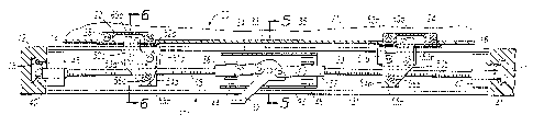
Referring to the drawings, wherein like reference numbers represent like
elements throughout the several drawings, Fig. 1 shows a locking window
assembly 10
including a window frame 12, an upper window sash 20 and a lower window sash
30.
The frame 12 and window sashes 20 and 30 may be made from any suitable
material
such as extruded aluminum, extruded vinyl, fiberglass, wood, composite
materials and
the like. The window sashes 20 and 30 may include transparent panes made from
glass, plastic and the like. The window frame 12 includes jamb channels 14I
and 16
which retain the lower window sash 30. The upper window sash 20 is retained in
a
separate set of jamb channels (not shown). Jamb channel inserts 15 and 17 are
secured
in the upper portions of the jamb channels 14 and 16. Each insert 15 and 17
provides
a retaining ledge under which reciprocating rod tips 40 and 41 are locked when
the
lower window sash 30 is fully lowered. The inserts 15 and 17 preferably
provide
elevated surfaces in the upper portions of the jamb channels 14 and 16 which
prevent
the rod tips 40 and 41 from fully extending into the jamb channels 14 and 16
when the
lower sash 30 is raised. A lock handle 32 is mounted on the lower window sash
30
for locking and unlocking the window assembly 10, as more fully described
below.
While the lock handle 32 shown in the figures is in the form of a lever, other
handle
configurations such as rotating knobs or sliding bars may be used in
accordance with
the present invention. The lock handle 32 may optionally be provided with a
locking
mechanism, such as a key lock (not shown).
The lower window sash 30 has pivot pins 18, 19 which are mounted in
conventional balance shoes (not shown) which slide in the jamb channels 14, 16
when
the lower sash 30 is raised and lowered. The pivot pins 18 and 19 also retain
the
lower sash 30 in the window frame 12 when the locking assembly is fully
unlocked and
the lower window sash is tilted inward for cleaning or the like.
Figs. 2-4 are top sectional views of the window locking assembly of the
present
invention in various locking positions. In Fig. 2, the locking assembly is in
the fully
locked position which secures the upper sash 20 to the lower sash 30. In this
fully
2191821
-5-
locked position, the lower sash 30 is also prevented from sliding within the
channels 14
and 16. In Fig. 3, the locking assembly is in the unlocked, sliding position
which
allows the upper and lower window sashes 20 and 30 to slide with respect to
each
other, and which permits the lower window sash 30 to slide within the channels
14
and 16. In Fig. 4, the locking assembly is in the fully unlocked, tilt
position, which
allows the lower window sash 30 to be tilted away from the window frame 12 for
purposes of cleaning or the like. In addition, the upper sash 20 may be
provided with
a conventional tilting mechanism including pivot pins at the lower portion of
the sash
which pivotally retain the upper sash in the window frame.
As shown in each of Figs. 2-4, the locking assembly in accordance with a
preferred embodiment of the present invention includes a lock handle 32
rotatably
mounted on the lower window sash frame 3 I by means of a pivot member 33 'such
as
a shaft, pin or bolt which is secured to a housing 93. Links 34 and 35 connect
the lock
handle 32 to reciprocating couplings 36 and 37. Each coupling 36, 37 is
connected to
a reciprocating rod 38, 39 which extends toward the window frame 12. Each
reciprocating rod 38, 39 has a rod tip 40, 41 which may be extended outwardly
from
the lower window sash frame 31 for engagement with the jamb channel 14, 16.
When
the lock handle 32 is rotated clockwise into the fully locked position shown
in Fig. 2,
the links 34 and 35 preferably are offset at a slight angle of about 5 degrees
with
respect to the reciprocating rods 38 and 39. This provides an over the center
locking
action which prevents retraction of the rods 38 and 39 if axial pressure is
applied to
the rod tips 40 and 41. Movement of the reciprocating rods 38 and 39 is guided
by
bushings 46 and 47, and bent tabs 44 and 45. In the preferred embodiment shown
in
Figs. 2-4, the reciprocating rods 38 and 39 are threaded along their lengths,
which
allows the rod tips 40 and 41 to be adjusted into the appropriate position
with respect
to the channels 14 and 16.
The locking assembly shown in Figs. 2-4 also includes cam assemblies SOa
and SOb which act to secure the upper window sash 20 to the lower window sash
30.
Each cam SOa, SOb is rotatably mounted on the lower window sash frame 31 by
means
of a pivot member 52a, 52b such as a shaft, pin, or bolt which is fastened to
a
bracket S la, S 1b. Each bracket S la, S l b is secured to the lower sash
frame 31 by
fasteners such as screws 53a, 53b. The cams SOa and SOb are received within
keeper
slots 22 and 24 which are secured to the upper sash frame 21 by fasteners such
as
2191821
-6-
screws 26. The cam SOa is rotated about the pivot member S2a by the
reciprocating
movement of the rod 38. A threaded carrier S4a connected to the threaded
reciprocating rod 38 has a screw pin SSa that engages in a slot S6a which
extends
through the cam SOa. Reciprocating movement of the rod 38 and carrier S4a thus
S actuates the cam SOa to thereby rotate into a locked or unlocked position.
The threaded
carrier S4a may be adjusted to the desired axial position on the threaded rod
38 in
order to provide optimum engagement between the cam SOa and the keeper 22. The
cam SOa includes a latch portion 60a that is receivable within a keeper slot
22 in the
upper window sash frame 21. In a similar manner, the cam assembly SOb is
actuated
by a threaded carrier S4b and screw pin SSb mounted on the threaded
reciprocating
rod 39. The pin SSb extends through a slot S6b in the cam SOb. Reciprocating
movement of the rod 39 causes the cam SOb to rotate about the pivot member S2b
to
thereby engage or disengage the cam latch 60b within the keeper slot 24 of the
upper
window sash frame 21.
1S In the fully locked position shown in Fig. 2, the lock handle 32 is rotated
about
the pivot member 33 to a position almost flush against the lower window sash
frame
31. In this position, the reciprocating rods 38 and 39 are fully extended such
that the
rod tips 40 and 41 extend into the jamb channels 14 and 16 underneath the
retainer
inserts 1S and 17. The lower window sash 30 is thus locked against relative
movement
within the window frame 12 through the contact of the end tips 40 and 41 and
the
undersides of the retainer inserts IS and 17. When the rod tins 40 and 41 are
fnliv
inserted into the jamb channels 14 and 16, each tip contacts the side of its
respective
jamb channel to produce a camming action between the rod tips and the sides of
the
jamb channels which draws the upper and lower window sashes 20 and 30
together.
2S In the fully locked position shown in Fig. 2, the upper window sash 20 and
lower window sash 30 are also secured against relative movement. This is
accomplished by positioning the lock handle 32 against the lower window sash
frame
31 as shown to thereby fully extend the reciprocating rods 38 and 39. In the
fully
extended position, the reciprocating rods 38 and 39 force the cams SOa and SOb
to
rotate into the positions shown in Fig. 2 in which the cam latches 60a and 60b
are
inserted into the keeper slots 22 and 24 in the upper window sash frame 2.1.
The fully locked position of the locking assembly shown in Fig. 2 provides
improved securement due to the use of multiple locking points. Contrary to
_ 21982 ~.
_7_
conventional lock arrangements, the locking assembly shown in Fig. 2 provides
four
contact points for securing the window in the locked position. Relative
movement
between the upper and lower window sashes is prevented by insertion of the two
cam
latches 60a and 60b into the keeper slots 22 and 24 of the upper window sash
frame
S 21. In addition, sliding movement of the lower window sash 30 relative to
the window
frame 12 is prevented through the use of two contact points. Reciprocating rod
tips
40 and 41 extend from the ends of the lower window sash frame 31 to engage
underneath retainer inserts 15 and 17 in the window frame 12. Thus, the four-
point
locking assembly shown in Fig. 2 provides improved securement in comparison
with
conventional locking assemblies.
Fig. 3 illustrates the locking assembly in the unlocked, sliding position. The
lock handle 32 is rotated counterclockwise from the position shown in Fig. 2
to~thereby
retract the reciprocating rods 38 and 39 a sufficient distance such that the
rod tips 40
and 41 are no longer underneath the retainer inserts 15 and 17. In this
position, each
rod tip 40, 41 is free to slide within its respective channel 14, 16 against
the surface
of its respective retainer insert 15, 17. However, the rod tips 40 and 41 are
still
extended a sufficient distance from the lower window sash frame 31 such that
they are
guided within the jamb channels 14 and 16 as the lower window sash 30 is
raised and
lowered.
In the unlocked, sliding position shown in Fig. 3, the cams SOa and SOb are
rotated out of engagement with the keeper slots 22 and 24 by the reciprocating
movement of the rods 38 and 39. Thus, in the position shown in Fig. 3, the
upper and
lower window sashes 20 and 30 are free to slide in relation to each other.
Fig. 4 illustrates the locking assembly of the present invention in the fully
unlocked, tilt position. The lock handle 32 is raised and rotated
counterclockwise from
the position shown in Fig. 3 to a position which causes the reciprocating rods
38 and
39 to be fully retracted into the lower window sash frame 31. In this
position, the
reciprocating rod tips 40 and 41 no longer ride within the jamb channels 14
and 16,
thereby allowing the lower window sash 30 to be tilted by rotation about the
pivot pins
18 and 19. In the fully unlocked position shown in Fig. 4, the cam latches 60a
and
60b remain disengaged from the keeper slots 22 and 24 of the upper window sash
frame 21.
~.~.~~1
_g_
Figs. S and 6 are side sectional views taken through Fig. 2 showing a window
locking assembly in accordance with a preferred embodiment of the present
invention.
Upper window panes 70 are mounted in the upper window sash frame 21 by means
of
a spacer 71 made of steel, aluminum or the like, and seals 72, 73 and 74.
S Alternatively, the spacer 71 and seal 72 can be provided as a single
component such
as aluminum reinforced butyl rubber. While double-pane windows are shown in
Figs. 5 and 6, it is to be understood that single=pane windows as well as
multiple-pane
windows are embodied by the present invention. A glazing lock strip 76 secures
the
upper window panes 70 to the upper window sash frame 21. As shown in Fig. 6,
the
keeper 22 is fastened to an aluminum reinforcing member 82 inside the frame 21
by
fasteners such as screws 26. A bottom cover 78 is secured to the upper window
sash
frame 21. The frame 21 includes an upwardly extending lip 79. Weather
stripping 80
is mounted in a groove in the upper window sash frame 21.
As shown in Figs. 5 and 6, the lower window sash 30 includes window panes
85 which are separated by a spacer 86, and which are sealed to the lower
window sash
frame 31 by a series of seals 87, 88 and 89. The spacer 86 and seal 87 can
alternatively be provided as a single component such as aluminum reinforced
butyl
rubber. A retainer strip 91 secures the lower window panes 85 within the lower
window sash frame 31. In Fig. 5, a housing 93 made of metal or the like is
fastened
to the lower window sash frame 31 by any suitable means such as screws,
rivets,
welding or the like (not shown) which are preferably anchored in an aluminum
reinforcing member 96. The housing 93 contains the pivot member 33, links 34
and 35, and reciprocating couplings 36 and 37 of the window locking assembly
of the
present invention. A spring 97 surrounds the pivot member 33 and bears against
the
housing 93 and lock handle 32 in order to force the lock handle 32 downward
while
permitting limited vertical movement of the lock handle. A cover plate 94 is
secured
to the frame 31 to thereby conceal the handle and other components of the
locking
assembly, and to permit access thereto for repair or replacement. The aluminum
reinforcing member 96 provides structural support for the lower sash frame 31.
As
shown in Fig. 6, the cam SOa is pivotally mounted on the bracket S la which in
turn
is secured to the lower frame 31 by a screw which is anchored to the aluminum
reinforcing member 96. Likewise, the keeper 22 is secured to the aluminum
reinforcing member 82 in the upper frame 21 by means of the screws 26. This
2191821
-9-
anchoring of the cam and keeper assemblies to the aluminum reinforcing members
provides additional security against forced entry. The lower window sash frame
31
includes a downwardly extending lip 95 which engages the upwardly extending
lip 79
of the upper window sash frame 21 in order to guide the upper and lower sashes
20
and 30 into proper alignment when the sashes are closed, as shown in Figs. 5
and 6.
In addition to providing a weather-tight seal, the extending lips 79 and 95
provide
additional securement against unwanted entry by preventing the upper and lower
window sashes 20 and 30 from being pulled apart from each other in a
horizontal
direction as shown in Figs. 5 and 6.
Fig. 7 shows a portion of the lower window sash frame 31 with the lock
handle 32 in the fully locked position, and with the lock handle 32 in the
fully
unlocked, tilt position (in phantom). The lock handle 32 rides in a slot S
which has
a stepped portion toward its right side. This stepped portion permits the lock
handle 32
to be moved horizontally from the left, fully locked position (as shown in
Fig. 2) to
the middle, unlocked sliding position (as shown in Fig. 3), but requires the
lock
handle 32 to be moved vertically before it can be positioned in the fully
unlocked, tilt
position (as shown in Fig. 4). As shown in Fig. 5, the spring 97 forces the
lock
handle 32 downward, while permitting limited vertical movement of the lock
handle.
In this manner, the lock handle 32 simply moves horizontally from the fully
locked
position to the unlocked sliding position, but requires additional
manipulation in the
vertical direction against the force of the spring 97 before the assembly can
be set in
the tilt position.
The locking assembly of the present invention provides several advantages over
conventional window locking arrangements. In accordance with the present
invention,
a single operating handle may be used to achieve multiple locked and unlocked
positions. Depending on the position of the handle, the assembly may be placed
in a
fully locked position, placed in an unlocked, sliding position, or placed in a
fully
unlocked, tilting position. Furthermore, the locking assembly of the present
invention
provides a highly secure, multiple-point locking system which greatly reduces
the risk
of unwanted entry. In the preferred embodiment, the upper and lower window
sashes
are locked to each other at two separate points, and the sashes are locked
within the
window frame at two additional points of contact. A highly secure locking
mechanism
is therefore provided which can be actuated using a single handle. The
invention
2191821
- l~ -
having been disclosed in connection with the foregoing variations and
examples,
additional variations will now be apparent to persons skilled in the art. The
invention
is not intended to be limited to the variations specifically mentioned, and
accordingly
reference should be made to the appended claims rather than the foregoing
discussion
of preferred examples, to assess the scope of the invention in which exclusive
rights
are claimed.