Language selection

Search

Patent 2191966 Summary

Third-party information liability

Some of the information on this Web page has been provided by external sources. The Government of Canada is not responsible for the accuracy, reliability or currency of the information supplied by external sources. Users wishing to rely upon this information should consult directly with the source of the information. Content provided by external sources is not subject to official languages, privacy and accessibility requirements.

Claims and Abstract availability

Any discrepancies in the text and image of the Claims and Abstract are due to differing posting times. Text of the Claims and Abstract are posted:

  • At the time the application is open to public inspection;
  • At the time of issue of the patent (grant).
(12) Patent: (11) CA 2191966
(54) English Title: FLUOROSCOPICALLY VIEWABLE GUIDEWIRE
(54) French Title: FIL DE GUIDAGE POUVANT ETRE VISUALISE PAR FLUOROSCOPIE
Status: Expired and beyond the Period of Reversal
Bibliographic Data
(51) International Patent Classification (IPC):
  • A61B 05/00 (2006.01)
  • A61M 25/00 (2006.01)
  • A61M 25/01 (2006.01)
(72) Inventors :
  • DAIGLE, JAMES B. (United States of America)
  • DE MELLO, RICHARD M. (United States of America)
  • FLIGHT, BRUCE W. (United States of America)
(73) Owners :
  • BOSTON SCIENTIFIC CORPORATION
  • BOSTON SCIENTIFIC LIMITED
(71) Applicants :
  • BOSTON SCIENTIFIC CORPORATION (United States of America)
  • BOSTON SCIENTIFIC LIMITED (Bermuda)
(74) Agent: SMART & BIGGAR LP
(74) Associate agent:
(45) Issued: 2004-11-16
(86) PCT Filing Date: 1995-06-27
(87) Open to Public Inspection: 1996-01-18
Examination requested: 2002-03-18
Availability of licence: N/A
Dedicated to the Public: N/A
(25) Language of filing: English

Patent Cooperation Treaty (PCT): Yes
(86) PCT Filing Number: PCT/US1995/008087
(87) International Publication Number: US1995008087
(85) National Entry: 1996-12-03

(30) Application Priority Data:
Application No. Country/Territory Date
08/270,034 (United States of America) 1994-07-01

Abstracts

English Abstract


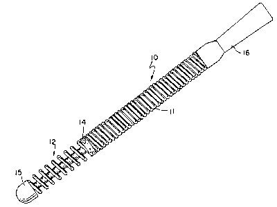
A guidewire (10) adapted to be inserted into a vascular vessel or into a
catheter that is to be inserted into a vascular vessel or the like.
The guidewire comprises a coil of flexible radiotransparent wire having a
proximal section (11) and a distal section (12). The proximal
section (11) is formed of a coil of wire having abutting turns and distal
section is formed by the same coil of wire with the turns of wire
being spaced from each other. A layer of radiopaque material of predetermined
length is disposed in a predetermined location on the distal
section, the interior of the layer being interstitially disposed within the
outer surface of the coil. A hemispherical tip (15) is disposed at
the distal end of the distal section (12). A small braze (14) is made at the
juncture between the proximal section and the distal section to
prevent spreading of the coils from the abutting relationship in the proximal
end of said guidewire.


French Abstract

Un fil de guidage (10) adapté pour être inséré dans un vaisseau vasculaire ou dans un cathéter devant être introduit dans un vaisseau vasculaire ou similaire. Le fil de guidage comprend une spirale de fil radiotransparent flexible comportant une section proximale (11) et une section distale (12). La section proximale (11) est formée d'une spirale de fil métallique ayant des spires en butée et une section distale est formée par la même spirale de fil métallique, les spires étant espacées les unes des autres. Une couche de matériau opaque aux rayonnements, de longueur prédéterminée, est placée dans un emplacement prédéterminé sur la section distale, l'intérieur de la couche étant placée de manière interstitielle à l'intérieur de la surface extérieure de la spirale. Une pointe hémisphérique (15) est placée au niveau de l'extrémité distale de la section distale (12). Une petite brasure (14) est effectuée à la jonction entre la section proximale et la section distale pour éviter la dispersion des spires depuis leur position de butée dans l'extrémité proximale du fil de guidage.

Claims

Note: Claims are shown in the official language in which they were submitted.


6
1. A guidewire adapted to be inserted into a vascular
vessel or into a catheter that is to be inserted into a
vascular vessel or the like, said guidewire comprising:
a coil of flexible radiotransparent metal wire, said
coil having a proximal section and a distal section, said
proximal section being formed of a coil of wire having
abutting turns, said distal section being formed by the same
coil of wire with the turns of wire being spaced from each
other;
a coating of radiopaque metal of predetermined length
disposed in a predetermined location on said distal section,
the interior of said coating forming an intermediate layer
comprising said substrate and said coating, said intermedi-
ate layer being interstitially disposed within the outer
surface of said coil and beneath said coating;
a tip disposed at the distal end of said distal sec-
tion;
means disposed at the juncture between the proximal
section and the distal section to prevent spreading of the
coils from the abutting relationship in the proximal end of
said guidewire.
2. The guidewire according to claim 1 further includ-
ing a core wire axially disposed within said guidewire, the
diameter of said core wire being less in said distal section
than in said proximal section, said core wire being formed
of a radiotransparent metal.
3. The guidewire according to claim 2 wherein the
diameter of the core wire in the distal section is less than
about half the diameter of the core wire in the proximal
section.
4. The guidewire according to claim 1 wherein said
guidewire is formed of stainless steel or nickel titanium
alloys and said coating is formed of gold or platinum.

7
5. The guidewire according to claim 1 wherein the
coating has a thickness between about less than 0.0001 and
0.0006 inches.
6. The guidewire according to claim 1 wherein said
coating is disposed on both the inside and the outside of
the coils of the guidewire.
7. The guidewire according to claim 1 wherein the
diameter of the coil is between about 0.006 to 0.040 inches.
8. The guidewire according to claim 7 wherein the
diameter of the wire forming the coil is between about .0010
and .010 inches.
9. The guidewire according to claim 1 wherein coils
in the distal section are spaced apart and not in contact
with each other.
10. The guidewire according to claim 1 wherein said
coating is formed by ion implantation of said radiopaque
metal in said radiolucent metal.

8
11. A guidewire adapted to be inserted into a vascular
vessel or into a catheter that is to be inserted into a
vascular vessel or the like, said guidewire comprising:
a coil of flexible radiotransparent metal wire, said
coil having a proximal section and a distal section, said
proximal section being formed of a coil of wire having
abutting turns, said distal section being formed by the same
coil of wire with the turns of wire being spaced from each
other;
a coating of radiopaque metal formed by ion implanta-
tion of said coil of wire, the interior of said coating
being interstitially disposed within the outer surface of
said coil, said coating being of predetermined length dis-
posed in a predetermined location on said distal section;
a tip disposed at the distal end of said distal sec-
tion;
means disposed at the juncture between the proximal
section and the distal section to prevent spreading of the
coils from the abutting relationship in the proximal end of
said guidewire.

Description

Note: Descriptions are shown in the official language in which they were submitted.


W0 96/01076 PCTIUS95/08087
2191966
FLUOROSCOPICALLY VIEWABLE GUIDEWIRE
Field of the Invention
The present invention relates to an improved guidewire
for insertion into a vascular vessel or into a catheter that
is to be inserted into a vascular vessel or the like.
Specifically the present invention relates to a coiled
guidewire which comprises a proximal section and a distal
section. A coating of gold or platinum is disposed on the
distal section of the guidewire and is formed such that it
is disposed in a predetermined location and is of predeter-
mined length. The interior of the coating is not merely
disposed on the substrate but is interstitially disposed
within the outer surface of the substrate. The guidewire
can be inserted into the vessel and can enable a physician
to identify the magnitude and location of a target site
through radiography.
Description of the Prior Art
Guidewires formed of coiled wire are well known in the
art and the disposition of core wires within the guidewire
is also known. For example, the United States Patents to
Daigle et al., 5,253,653; Claude, 5,084,022; Gambale et al.,
5,060,660, are illustrative of coiled guidewires. Mecha-
nisms to define radiopacity in a guidewire to define dark
images on coiled guidewires are also known to the art in,
for example, Gambale et al., 5,144,959, and Daigle et al.,
5,253,653.
Summary of the Invention
According to the present invention we have invented a
novel flexible, shapable guidewire which can be used by
itself or within a catheter sleeve. The guidewire of our
invention has a radiopaque tip disposed in its distal end.
While coatings have previously been disposed upon guidewire
tips to make them radiopaque for radiographic identification

CA 02191966 2004-07-08
76664-78
2
of their location, we have discovered when such materials
are merely coated upon guidewires they tend to have less
than satisfactory adhesion and processes for coating the
substrates can involve the use of deleterious chemicals.
Such markers have conventionally been made of silver, gold,
platinum, tantalum or other radiopaque bio-compatible
materials.
According to a preferred embodiment of the present
invention the radiopaque metal is applied to a stainless
steel coil by means of an ion beam deposition process. In
the ion beam deposition process the coating metal is
implanted beneath the surface of the substrate to effectuate
a bond. Such implantation is provided without the use of
chemicals and thus eliminates certain hazards in the product
associated with residual chemicals in the product when using
traditional electrochemical deposition processes. According
to the preferred embodiment of the invention the coil has a
substrate of stainless steel and an outer layer which is a
combination of the stainless steel and the ion implanted
coating disposed thereon. On top of the ion implanted layer
is a layer of the radiopaque material itself.
Such deposition methods eliminate the problems
associated with a guidewire that is stiff at the joint
between radiopaque coils and radiotransparent coils since
there is no need to braze, solder or adhesively attach
multiple components. Moreover the problem related to the
joint failing is also eliminated.
The guidewire construction of the present
invention enables a single length of coil to display varying
degrees of radiopacity traditionally associated with an
assembly of different materials. The coil's performance is

CA 02191966 2004-07-08
76664-78
3
not compromised due to stiffness created by component
attachment joints. The surface enhancement of the device is
by means of an ion beam deposition of dense materials
provides a denser and less porous deposition of these
materials over known electrochemical deposition methods.
Thus radiopacity can be enhanced without the introduction of
deleterious chemicals. Quite importantly, with the use of
an expanded coil in the distal section of the guidewire the
entire coil, both inside and out, can be coated with the
radiopaque materials.
The invention may be summarized according to one
aspect as a guidewire adapted to be inserted into a vascular
vessel or into a catheter that is to be inserted into a
vascular vessel or the like, said guidewire comprising: a
coil of flexible radiotransparent metal wire, said coil
having a proximal section and a distal section, said
proximal section being formed of a coil of wire having
abutting turns, said distal section being formed by the same
coil of wire with the turns of wire being spaced from each
other; a coating of radiopaque metal of predetermined length
disposed in a predetermined location on said distal section,
the interior of said coating forming an intermediate layer
comprising said substrate and said coating, said
intermediate layer being interstitially disposed within the
outer surface of said coil and beneath said coating; a tip
disposed at the distal end of said distal section; means
disposed at the juncture between the proximal section and
the distal section to prevent spreading of the coils from
the abutting relationship in the proximal end of said
guidewire.

CA 02191966 2004-07-08
76664-78
3a
According to another aspect the invention provides
a guidewire adapted to be inserted into a vascular vessel or
into a catheter that is to be inserted into a vascular
vessel or the like, said guidewire comprising: a coil of
flexible radiotransparent metal wire, said coil having a
proximal section and a distal section, said proximal section
being formed of a coil of wire having abutting turns, said
distal section being formed by the same coil of wire with
the turns of wire being spaced from each other; a coating of
radiopaque metal formed by ion implantation of said coil of
wire, the interior of said coating being interstitially
disposed within the outer surface of said coil, said coating
being of predetermined length disposed in a predetermined
location on said distal section; a tip disposed at the
distal end of said distal section; means disposed at the
juncture between the proximal section and the distal section
to prevent spreading of the coils from the abutting
relationship in the proximal end of said guidewire.
The many other features, objects and advantages of
the present invention can become apparent from and are set
out in more detail in the accompanying drawing and following
descriptions of the best mode of carrying out the invention.
Brief Description of the Drawing
The Figure is a side elevational view of a
guidewire according to the present invention.
Description of the Preferred Embodiments
Referring now to the Figure a coiled guidewire 10
is formed of a proximal section 11 and a distal section 12.
A braze 14 is disposed between the proximal section 11 and
the distal section 12. The two sections are formed of a

CA 02191966 2004-07-08
76664-78
3b
single coil of stainless steel wire having a diameter
between about .010 and .040 inches in diameter and formed of
wire having a diameter from .001 to .O1 inches. The
proximal section 11 of the coil is tightly wound with turns
touching and the distal section 12 being open wound with
turns not touching.

WO 96101076 PCT/US95/08087
~2i 91966
4
The guidewire 10 terminates in a hemispherical shaped tip 15
formed by welding, soldering, or brazing. ,
The distal section of the guidewire is generally be-
tween about one and five centimeters and the entire length ,
of the coil section is between about fifteen and fifty
centimeters, although the coil could extend over the full
length of the guidewire. The diameter of the tip 15 is
about the same as the diameter of the coiled guidewire 10.
The braze 14 is disposed between the proximal
section 11 and the distal section 12 to prevent the coil in
the proximal section 11 from stretching as the guidewire is
removed from the vascular conduit in which it is inserted,
and also to aid in guidewire torque transmission. No sig-
nificant stiffness is contributed by the braze.
The proximal end of the proximal section 11 has a
retaining device 16 disposed thereon. The retaining device
enables the person operating the guidewire to turn and
orient the guidewire within the vascular conduit.
A core wire 5 is disposed within the guidewire 10. The
core wire 5 is necked down or tapered from a larger diameter
to a smaller diameter at the braze 14 the diameter of the
core wire inside the distal section 12 is between about
0.002 to 0.006 inch and within the proximal section 10 is
about 0.020 inch. The tip of the core wire 5 is disposed
within the tip 15. The core wire provides stability to the
guidewire during its use.
The radiopaque material is disposed on the distal sec-
tion 12 by conventional ion implantation processes. A
predetermined length of the distal section of the guidewire
is impregnated with gold or other radiopaque material so as
to create a radiopaque distal section on an otherwise radio-
lucent coil. This is accomplished under vacuum whereby an
ion beam impinging on the coil surface causes the coil to
give off material creating an irregular substrate of micro-
scopic depth. A second ion beam, with vaporized radiopaque
material in its path, then impinges on the coil surface

WO 96/01076 PCTIU595108087
filling the irregular substrate and continues to deposit
radiopaque material to a controlled desired thickness.
It is apparent that modifications and changes can be
made within the spirit and scope of the present invention
5 but it is our intention, however, only to be limited by the
scope of the appended claims.
As our invention we claim.

Representative Drawing
A single figure which represents the drawing illustrating the invention.
Administrative Status

2024-08-01:As part of the Next Generation Patents (NGP) transition, the Canadian Patents Database (CPD) now contains a more detailed Event History, which replicates the Event Log of our new back-office solution.

Please note that "Inactive:" events refers to events no longer in use in our new back-office solution.

For a clearer understanding of the status of the application/patent presented on this page, the site Disclaimer , as well as the definitions for Patent , Event History , Maintenance Fee  and Payment History  should be consulted.

Event History

Description Date
Time Limit for Reversal Expired 2012-06-27
Letter Sent 2011-06-27
Inactive: IPC from MCD 2006-03-12
Grant by Issuance 2004-11-16
Inactive: Cover page published 2004-11-15
Letter Sent 2004-09-13
Amendment After Allowance Requirements Determined Compliant 2004-09-13
Letter Sent 2004-08-02
Pre-grant 2004-07-09
Inactive: Final fee received 2004-07-09
Inactive: Amendment after Allowance Fee Processed 2004-07-08
Amendment After Allowance (AAA) Received 2004-07-08
Inactive: Office letter 2004-03-23
Appointment of Agent Requirements Determined Compliant 2004-03-23
Revocation of Agent Requirements Determined Compliant 2004-03-23
Inactive: Office letter 2004-03-23
Letter Sent 2004-03-15
Notice of Allowance is Issued 2004-03-15
Revocation of Agent Request 2004-03-10
Appointment of Agent Request 2004-03-10
Inactive: Approved for allowance (AFA) 2004-02-26
Inactive: Status info is complete as of Log entry date 2002-04-11
Letter Sent 2002-04-11
Inactive: Application prosecuted on TS as of Log entry date 2002-04-11
All Requirements for Examination Determined Compliant 2002-03-18
Request for Examination Requirements Determined Compliant 2002-03-18
Application Published (Open to Public Inspection) 1996-01-18

Abandonment History

There is no abandonment history.

Maintenance Fee

The last payment was received on 2004-06-25

Note : If the full payment has not been received on or before the date indicated, a further fee may be required which may be one of the following

  • the reinstatement fee;
  • the late payment fee; or
  • additional fee to reverse deemed expiry.

Patent fees are adjusted on the 1st of January every year. The amounts above are the current amounts if received by December 31 of the current year.
Please refer to the CIPO Patent Fees web page to see all current fee amounts.

Owners on Record

Note: Records showing the ownership history in alphabetical order.

Current Owners on Record
BOSTON SCIENTIFIC CORPORATION
BOSTON SCIENTIFIC LIMITED
Past Owners on Record
BRUCE W. FLIGHT
JAMES B. DAIGLE
RICHARD M. DE MELLO
Past Owners that do not appear in the "Owners on Record" listing will appear in other documentation within the application.
Documents

To view selected files, please enter reCAPTCHA code :


To view images, click a link in the Document Description column. To download the documents, select one or more checkboxes in the first column and then click the "Download Selected in PDF format (Zip Archive)" or the "Download Selected as Single PDF" button.

List of published and non-published patent-specific documents on the CPD .

If you have any difficulty accessing content, you can call the Client Service Centre at 1-866-997-1936 or send them an e-mail at CIPO Client Service Centre.


Document
Description 
Date
(yyyy-mm-dd) 
Number of pages   Size of Image (KB) 
Representative drawing 1997-12-30 1 6
Description 1995-06-26 5 200
Abstract 1995-06-26 1 47
Drawings 1995-06-26 1 12
Claims 1995-06-26 3 88
Representative drawing 2004-03-03 1 9
Description 2004-07-07 7 237
Description 2004-11-14 7 237
Abstract 2004-11-14 1 47
Drawings 2004-11-14 1 12
Claims 2004-11-14 3 88
Reminder - Request for Examination 2002-02-27 1 119
Acknowledgement of Request for Examination 2002-04-10 1 180
Commissioner's Notice - Application Found Allowable 2004-03-14 1 161
Maintenance Fee Notice 2011-08-07 1 170
PCT 1996-12-02 5 273
Correspondence 2004-03-09 3 78
Correspondence 2004-03-22 1 14
Correspondence 2004-03-22 1 17
Correspondence 2004-07-08 1 37
Fees 1996-12-02 1 47