Language selection

Search

Patent 2192482 Summary

Third-party information liability

Some of the information on this Web page has been provided by external sources. The Government of Canada is not responsible for the accuracy, reliability or currency of the information supplied by external sources. Users wishing to rely upon this information should consult directly with the source of the information. Content provided by external sources is not subject to official languages, privacy and accessibility requirements.

Claims and Abstract availability

Any discrepancies in the text and image of the Claims and Abstract are due to differing posting times. Text of the Claims and Abstract are posted:

  • At the time the application is open to public inspection;
  • At the time of issue of the patent (grant).
(12) Patent Application: (11) CA 2192482
(54) English Title: CLAMP CONNECTOR FOR THE ASSEMBLY OF PREFABRICATED SHAPED-SECTION BARS TO FORM SCAFFOLDING
(54) French Title: DISPOSITIF DE RACCORDEMENT A BLOCAGE POUR ASSEMBLER DES BARRES PROFILEES PREFABRIQUEES ET FORMER UN ECHAFAUDAGE
Status: Deemed Abandoned and Beyond the Period of Reinstatement - Pending Response to Notice of Disregarded Communication
Bibliographic Data
(51) International Patent Classification (IPC):
  • E04G 7/30 (2006.01)
  • E04G 1/15 (2006.01)
  • E04G 5/16 (2006.01)
(72) Inventors :
  • KRAUSE, GUNTHER (Germany)
(73) Owners :
  • KRAUSE-WERK GMBH & CO. KG
(71) Applicants :
  • KRAUSE-WERK GMBH & CO. KG (Germany)
(74) Agent: SMART & BIGGAR LP
(74) Associate agent:
(45) Issued:
(86) PCT Filing Date: 1995-05-12
(87) Open to Public Inspection: 1995-12-21
Availability of licence: N/A
Dedicated to the Public: N/A
(25) Language of filing: English

Patent Cooperation Treaty (PCT): Yes
(86) PCT Filing Number: PCT/EP1995/001805
(87) International Publication Number: WO 1995034727
(85) National Entry: 1996-12-09

(30) Application Priority Data:
Application No. Country/Territory Date
G 94 09 418.7 U (Germany) 1994-06-10

Abstracts

English Abstract


A clamp connector for scaffolding must not only make
it possible to join two scaffolding components rapidly
and securely but also be inexpensive to manufacture, have
long life and be suitable for use with a wide variety
of scaffolding designs. To this end, the invention calls
for there to be an aperture (PA) in each of the shaped-
section bars of the scaffolding units to be fixed
together, the aperture being designed to hold a cross-
bar (121 and to be locked by a moving clamp (6).


French Abstract

L'invention vise à mettre au point un dispositif de raccordement à blocage pour échaffaudage qui permette d'une part d'assembler rapidement et de manière fiable deux éléments d'échafaudage, tout en étant par ailleurs économique à réaliser et durable, et adapté à des éléments d'échaffaudage de structures très diverses. A cet effet, il est prévu que les barres profilées des éléments d'échaffaudage à fixer comportent au moins une cavité (PA) retenant une traverse (12), et pouvant être fermée à l'aide d'une pièce de blocage (6) mobile.

Claims

Note: Claims are shown in the official language in which they were submitted.

Claims:
1. A clamp connector for prefabricated structural
elements for the assembly of a scaffolding, for example
shaped-section bars (P) and crossbars (12) or brackets
whereby
(a) an aperture (PA) is provided for receiving the
crossbars (12) or the brackets, the axis of symmetry (PQ)
of the aperture is directed transverse with respect to
the longitudinal axis (PL) of the shaped-section bars
(P), and the aperture is open with a slot (PA2) toward
the underside (PU) of the associated shaped-section bar
(P) so that the aperture can receive the associated
crossbar (12) or the bracket therethrough,
(b) the recess (PA) is dimensioned such that the
shape-section bar (P) rests in direction of its
longitudinal axis (PL) nonmovably on the crossbar (12) or
the bracket,
(C) clamps (6) are provided on the end areas (PP)
of the shaped-section bars (P), the clamps can be moved
at least partially parallel to the longitudinal axis (PS)
of the respective shaped-section bar (P) and can be
locked, the clamps in a closed position cover the slot
(Ps2) of the respective aperture PA) to clamp the
crossbar (12) or the bracket in said aperture (PA) are the
shaped-section bar P, characterized in that
(d) the apertures (PA) are provided in the end
areas (PF) of the shaped-section bars (P).
2. The clamp connector according to Claim 1,
characterized in that least two of the apertures (PA)
provided on the shaped-section bars (P) can be locked
with clamps (6) on each structural element (2, 3, 4).
3. The clamp connector according to Claim 1,
characterized in that the area (PA1) of the aperture (PA)
resting on the crossbar (12) or the bracket is shaped

such that it rests approximately with a flat contact on
the crossbar (12) or the bracket.
4. The clamp connector according to one of the
Claims 1 to 3, characterized in that a locking device (5
is provided, with the help of which the clamp (6) can be
locked at least in one closing and one opening position
with reference to the aperture (PA).
5. The clamp connector according to one of the
Claims 1 to 4, characterized in that the clamp (6) is
designed as a shaped-section piece parallel with the
associated shaped-section bar (P).
6. The clamp connector according to one of the
Claims 1 to 5, characterized in that the clamp (6) is
provided in direction of its longitudinal axis (64) on a
bar (62) with a slotted hole (62a), which bar has a
clamping surface, and through which slotted hole extends
a bolt (51) of the locking device (5), which bolt can be
screwed to the shaped-section bar (P).
7. The clamp connector according to Claim 6,
characterized in that the bolt (51) is designed as a
threaded bolt and the clamp (6) can be clamped by means
of a handle (52) provided on the bolt (51).
8. The clamp connector according to Claim 6 or 7,
characterized in that between the bar (62) and the
shaped-section bar (P) there is provided a spacer (PD)
such that the clamp (6) locked by means of the locking
device (5) is positioned approximately parallel with the
shaped-section bar (P).
9. The clamp connector according to one of the
Claims 1 to 8, characterized in that a pressure surface
(63) of the clamp (6) follows the cross-sectional shape

of the crossbar (12), the pressure surface can be clamped
to the crossbar (12) or the bracket (6).
10. The clamp connector according to one of the
Claims 1 to 9, characterized in that the shaped-section
bar (P) has a rectangular hollow shape and the clamp (6)
has a U-shape, and the belts (61) of the U-shape rest on
the sidewalls (PS) of the shaped-section bar (P).
11. The clamp connector according to one of the
Claims 1 to 10 for connecting a platform (2), an at least
diagonal longitudinal or transverse reinforcement (4) of
a longitudinally or transversely extending railing or
intermediate spar (31, 32) of the railing or of another
similar structure element to a crossbar (12) or a
bracket on a post (11).

Description

Note: Descriptions are shown in the official language in which they were submitted.


LE P8tl~' T `~ E 21 924 82
CLAMP ~;u~ R FOR l'HE ASSEMBLY OF
PREFA~RICATED SHAPED-SECTIoN 13ARS TO FORM SCA~FOLD~NG
5 Description:
~ he invention relates to a clamp connector acco}ding
to the Oberbegriff o~ Claim l
A clamp cnn~ntor is kno~n from the U.S. Patent No.
2 308 831, for example, for r~Stening of crossbars to
10 spars, in which 21 clarping part is screwed to the pipe
Qnd, which clamping part has ~ tl-shaped recess for
receiving the pipe to be ~astened. The recesses such can
be closed off by a ~lovable plate adjustable in its
length .
Great Britain Patent No. 1 25Q 607 p~tent describ_s
a C~J- Ll=a~ol~ding clamp connector, ~hereby here two plates
arr~nged sp~ced ~rom onn another are screwed or welded to
the end Or, for example, a crossbar. The slot provide~L
in these plates for recei~ring a scaffolding frame elem~nt
20 can be closed off by a key.
Cla~;p connectors of this type are extensive~y needed
in the building of sca~olding in order to be able to
safely and quickly connect the fr~me elements, platforms,
spars~ reinforcements and similar 8tructural elements
25 with one another, in particular, in the case of
3carfoldings consisting of prafabricated structurzll
ele~ents .
~ hereas the shapes of the structur~l element to be
connected can be essential shaped as deslred at the
30 .-nnnf~nt~n~ point for the clamp connector, and merely only
its sa~e ~astening must be guar~nteed, the crossbars and
brackets are designe~ with a continuously constant cross
section adapted in shape to the clamp connector.
The purpose of the invention is to design such clamp
35 connectors so that they consist of only a ~e~ structural
parts, ca~ be in~y~nsively manufactured and highly
~LL~s:,ed, supporting weldins seams can be eliminated

2~ 924~2
The purpose i8 ~ttained according to the invention
with the charaateristics of Claim 1.
Such ~ clamp connector requires only very few
additional connecting elements and does not require any
5 supporting welding connections.
~ he invention will be discussed in greater detail
hereinafter in connection with one exemplary embodiment
and the dr~wings, which are schematical illustrations.
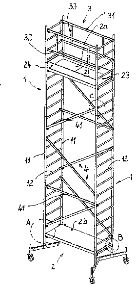
Figure 1 illustrates a (travelling) sca~olding
10 built by means of clamp connectors of the invention,
Figures 2 to 4 illustrates ~enlarged~ clamp
cohnectors of Figure 1 corresponding with the details A,
B and C,
Figure 5 illustrates the clamp connector o~ Figure
15 4, however, it is shown inclined and ~urther enlarged,
Figure 6 illustr~tes a ralling area and Figure 7 a
platform o~ Figure l, however, shown slightly turnsd, all
in a three-dimensio~al illustr~tion,
Figure 8 is a front view of the clamp connector o~
20 the invention, and
Figure g is a side view along direction arrow D of
Figure 8
Figure 1 shows a typical scaffolding, which i5 here
provided ~ith an undercarriage. It consists of a number
25 of structural elements, which can be ~ound ag~in and
again in such scaffolding. Lateral multiple frame
elements 1 cohsiSt o~ vertical posts 11 and horizontal
crossbars 12 c nnn~oting the posts 11. The crossbars 12
are here also used as ladder rungs and are welded with a
30 suitably narrow sp~cing on the posts 11. I'hey are
therefore well suited tc connect the frame el~ment 1 to
the other structural elemen~s of the ~caf~olding. Short
brackets can be provided on the posts ll, in particular
when connections of cther structural elements are needed
35 in places where a crossbrr 12 is not available, for
example, when transverse reinforcements must be
connected. ~he following discussions g~nerally referred

4 `~ 21 q24~2
to crossbars 12 appl~ ~lso to those brackets not showh in
the dr~wings.
Thus two hori20ntal platforms 2 are fastened to the
~ra3me elements 1, of which platforms the upper platform
5 2a has an opening ~l, which c~n be closed off ~ith a flap
22 (Figure 7), and i~ de~ined by transverse and
longitudin~l edges 23 and 24. Furthermore, the platform
2a is secured by a railing 3, which consists of railing
spars ll, int~ te spars 32 and connecting pieces 33
10 lFigure 6). The lo~er platrorm 2b does not nee~ a
railing 3. Finally, longitudinal reinforcements 41 o~ a
reinf~ t 4, which may possibly also include
transv~:rse reinforcements, are provided, which together
with the platforms 2 give the scaf~olding suf~icient
15 rigidity.
The cros~bars 12 con~ist advantageously, like the
postG ll, of circular-cylindrical plpes, however, other
shapes are concseivable and can also be easily connected
to the cl~mp connector of the invention, which is then to
20 be designed slightly differently in shape. In contrast
to this, all other struotural elements are asEiembled out
of shaped-6ection bars P, which have in cross #eCtion
rectangular hollow shape as can be seen with greater
detzil in Figures 4 and 5. These shaped-section bars P
~5 can also instead have a differently shaped cross section.
HoweVer, indepehdent froln the respective ~LU-:LULal
~lement, the shaped-section bars P advantageously have
the same dimensions so that uniformly dimensioned clamp
connectors are possible and only ~ew different structural
30 elemen~s ~re ne~ded.
The area of ~ clamp connector of the invention can
be seen in detail in Fi~ures 8 and ~. ~he shaped-section
bar P is ~on both sides) closed off with a plug 5. An
aperture PA is provided in an end area PF of the shaped-
35 section bar P, has an axis of 8ymmetry PQ perp~ iolllArwith respect to the longitudinal ~xis PI of the shaped-
section bar P, and is sh~ped like the crossbar 12 its

~ ~ 2192482
upper area PAl in the direction of th~ longitudinal axis
121 (Figure 4) Or the arossbar 12 so that the aperture PA
rests flat on the associated crossbar 12 A slot PA2
opens the aperture PA towa~d the underside PU of the
shaped-section bar P, and is ~ ned such that the
shaped-section bar P rests ~ith only a little clearance
in the direotion o~ its longitudinal axis PL above the
crossbar 12. Feed -~lopes PE assist in holding the
crossbar 12 in the aperture PA.
o A bolt S1 of a locking devLce 5 is stationarily,
however, screwably, provided engaging a thread 51a on the
~haped-section bar P. A spacer PD is welded to the
shaped-section bar l? to extend the ihternal thread of the
thread 51a and to ensure that a clamp 6 is spaced at such
lS a distance from the shaped-section bar P that it is
approximately parallel with the same when the associ~t~d
crossbar lZ is placed in the aperture PA and i5 held by
the clamp 6. A handle 5z fixed on the bolt 51 malces the
operation thereof easier.
The clamp 6 is designed with a U-shape, the belts 61
of which rest oh the sidewalls Ps of the associated
shaped-section bar P~ _uLLuull~ing s2me ~rith little
clearance, whereas the connecting bar 62 contacts the
spacer Pl~. A slotted hole 62a is cut into the bar 62
along the direction of the longitudinal 2XiS 64 of the
clamp 6 (Figure S). The bolt 51 extends through the
slotted hole. The slotted hole allows limited
longitudinal ~ovement of the alamp 6. The arrangement is
sUch that (in Figure 8) the clamp 6 can be moved so f~r
to the right that the slût PA2 is no longer covered
thereby. ~he position of the clamp 6 illustrated in
Figure 8 ~uLL~ullds with the final positiûn in the
zlssembled state of Figure 4.
The clamp 6 then cl~mps the crossbar 12 with a
~L~=s_ule surface 63 arranged in the t~o belts 61, the
shape ûf which is adapted to the cross sectlonal shape ûf
the crossbar 12 such that a ~lat cont~ct is guaranteed

~-- 2~924~2
and the surface ~ e is be~rable throughout the
contaat area.

Representative Drawing
A single figure which represents the drawing illustrating the invention.
Administrative Status

2024-08-01:As part of the Next Generation Patents (NGP) transition, the Canadian Patents Database (CPD) now contains a more detailed Event History, which replicates the Event Log of our new back-office solution.

Please note that "Inactive:" events refers to events no longer in use in our new back-office solution.

For a clearer understanding of the status of the application/patent presented on this page, the site Disclaimer , as well as the definitions for Patent , Event History , Maintenance Fee  and Payment History  should be consulted.

Event History

Description Date
Inactive: IPC from MCD 2006-03-12
Time Limit for Reversal Expired 2003-05-12
Application Not Reinstated by Deadline 2003-05-12
Inactive: Status info is complete as of Log entry date 2002-06-26
Inactive: Abandon-RFE+Late fee unpaid-Correspondence sent 2002-05-13
Deemed Abandoned - Failure to Respond to Maintenance Fee Notice 2002-05-13
Letter Sent 1997-10-14
Reinstatement Requirements Deemed Compliant for All Abandonment Reasons 1997-09-26
Deemed Abandoned - Failure to Respond to Maintenance Fee Notice 1997-05-12
Application Published (Open to Public Inspection) 1995-12-21

Abandonment History

Abandonment Date Reason Reinstatement Date
2002-05-13
1997-05-12

Maintenance Fee

The last payment was received on 2001-05-01

Note : If the full payment has not been received on or before the date indicated, a further fee may be required which may be one of the following

  • the reinstatement fee;
  • the late payment fee; or
  • additional fee to reverse deemed expiry.

Please refer to the CIPO Patent Fees web page to see all current fee amounts.

Fee History

Fee Type Anniversary Year Due Date Paid Date
Registration of a document 1997-01-16
Reinstatement 1997-09-26
MF (application, 2nd anniv.) - standard 02 1997-05-12 1997-09-26
MF (application, 3rd anniv.) - standard 03 1998-05-12 1998-04-23
MF (application, 4th anniv.) - standard 04 1999-05-12 1999-04-30
MF (application, 5th anniv.) - standard 05 2000-05-12 2000-04-27
MF (application, 6th anniv.) - standard 06 2001-05-14 2001-05-01
Owners on Record

Note: Records showing the ownership history in alphabetical order.

Current Owners on Record
KRAUSE-WERK GMBH & CO. KG
Past Owners on Record
GUNTHER KRAUSE
Past Owners that do not appear in the "Owners on Record" listing will appear in other documentation within the application.
Documents

To view selected files, please enter reCAPTCHA code :


To view images, click a link in the Document Description column. To download the documents, select one or more checkboxes in the first column and then click the "Download Selected in PDF format (Zip Archive)" or the "Download Selected as Single PDF" button.

List of published and non-published patent-specific documents on the CPD .

If you have any difficulty accessing content, you can call the Client Service Centre at 1-866-997-1936 or send them an e-mail at CIPO Client Service Centre.


Document
Description 
Date
(yyyy-mm-dd) 
Number of pages   Size of Image (KB) 
Representative drawing 1999-06-11 1 25
Description 1995-12-21 5 192
Claims 1995-12-21 3 100
Abstract 1995-12-21 1 14
Cover Page 1997-04-16 1 17
Drawings 1995-12-21 3 75
Courtesy - Abandonment Letter (Maintenance Fee) 1997-08-04 1 188
Notice of Reinstatement 1997-10-14 1 171
Reminder - Request for Examination 2002-01-15 1 117
Courtesy - Abandonment Letter (Maintenance Fee) 2002-06-10 1 183
Courtesy - Abandonment Letter (Request for Examination) 2002-06-25 1 170
International preliminary examination report 1996-12-09 35 778
Courtesy - Office Letter 1997-01-28 1 20
PCT Correspondence 1997-02-05 1 26