Note: Descriptions are shown in the official language in which they were submitted.
21 92523
- CUTTING DRUM FOR AN OPEN CAST WINNING APPARATUS
PERFORMING ITS WINNING ACTION IN BOTH DIRECTIONS OF TRAVEL
BACKGROUND OF THE INVENTION AND PRIOR ART
The invention relates to a cutting drum for an open cast winning
apparatus performing its winning action in both directions of travel,
automotive on an undercarriager comprising cutter bars on its periphery,
5 said cutter bars being interconnected in peripheral direction by two rings
and holding cutter tools consisting of picks and pick holders, the pick
holders including the picks being so pivotally mounted around a pivoting
axis that the picks pointing in the direction of rotation, due to the
excavation resistance, automatically swivel into the cutting position when
10 engaging the material to be worked, the picks oriented in opposite
direction simultaneously swivelling from the angular position of cutting of
the picks performing the excavation work.
For underground coal winning a cutting drum comprising pivotal cutting
tools consisting of double-edged pick holders according to DE-GM
15 17 49 015 is known. The pick holders are adapted to swivel around bolts
provided in the drum body in parallel relationship to the drum axis. In their
end positions the pick holders are fixed by securing means latching into
depressions in the bolt.
According to DE 39 20 011 a cutting drum for use in open pit mining is
20 known which consists of a latticed drum base body on the periphery of
which cutter bars are provided in axial direction in evenly spaced
relationship, interconnected in peripheral direction by rings. On their side
forming the drum circumference, the cutter bars support pick holders on
which, as in the solution cited above as known state of the art, cutting
25 picks are provided in V-shaped manner in pairs each pivotally in a
common joint, parallel to the drum axis. In this context the pick pointing
in the direction of rotation, is in working position while the other pick
21 ~2523
-
facing away, is automatically swivelled to an angle out of the region of
excavation. In the terminal positions the pick holders can be secured by
means of spring elements latching into depressions. This known solution,
however, still has shortcomings:
5 - The disposition of the picks with their tips widely spaced from the
center of the cutter bar cross-section (neutral fibre) generates
large torque in the cutter bar as well as the risk of unacceptable
torsional oscillations (rattling).
- The material loosened by the pick tips is carried along by the sheet
metal scrapers provided between the pick holders. If ridges remain
between the grooves dug by the pick tips when loosening hard
material, these are broken loose by the sheet metal scrapers,
provided the latter are of a sufficiently strong construction. The
large spacing of the outer edges of these sheet metal scrapers from
the center of the cutter bar cross-section likewise results in
considerable strains. In addition, the central disposition of the sheet
metal scrapers of the cutter bar is detrimental to the flow of the
material to be mined.
- The pick holders disposed in radial direction outside the cutter bar
result in a large radial spacing from the cutting orbit up to the
annular chute surface. For a given cutting orbit diameter little
volume for construction is left for the structural components within
the annular chute.
A need still exists to structurally so design the cutting drum for an open
25 cast winning apparatus performing its winning action in both directions of
travel that it is robust and ensures high operational reliability and
availability in a simple technical structure while minimizing material
expenditure.
21 92523
GENERAL DESCRIPTION OF THE INVENTION
In accordance with the invention a mining apparatus is provided as set
out in the opening paragraph, wherein
- two pick holders, of which the one pick holder is provided for
right-hand cutting work and the other pick holder for left-hand
cutting work, are disposed in hinged manner in the direction of
rotation on opposite sides of a cutter bar in the regions of those of
their edges which are directed towards the interior of the cutting
drum and, together with sheet metal scrapers connecting the pick
holders, form cutting tools, consisting of two or more pairs, said
pairs being disposed on both sides of the cutter bars,
- interchangeable picks are attached to the pick holders,
- the sheet metal scrapers are designed as blades in the region of
the pick tips,
15 - connecting bars are provided between the cutting tools, on
opposite sides of the cutter bar so arranged that the cutting tools
pointing in opposition to the direction of rotation are raised from
the cutter bar and swivelled at an angle outside the excavation
being cut while the picks pointing in the peripheral direction
perform excavation work and are pressed against the cutter bar by
the excavation force
- latches are provided on the connecting bars, holding the picks in
their excavating position or non-excavating position, as the case
may be, with a force sufficiently great to avoid tipping over of the
pick holders by their own weight when the cutting drum is rotating
and
- when changing the cutting direction, the picks of one cutter bar
side are moved in such a manner against the force of the latches
due to contact of the picks and blades with the mineral matter to
be cut loose that the picks now pointing in the direction of rotation
21 92523
-
are swivelled into the excavating position and the picks on the
opposite side are swivelled into the non-excavating position.
The blades and rear sheet metal plates ensure improved forwarding and a
better flow of the loosened material being mined. Coalescing strata may
5 likewise be excavated. Due to the larger support base of the pick holders
from the center of the joint to the outer edge of the cutter bar lesser
forces arise at the mountings of the pick holders. The torque on the
cutter bars is thus reduced. By the disposition of a cutting tool on both
sides of a cutter bar, a lower construction height in respect of the cutter
10 bar is attained from the outer diameter of the annular chute towards the
cutting orbit.
The picks are provided - in a known manner - on helical lines on the
drum circumference, the lead of which is so selected that the groove
ripped into the material to be excavated by the pick is followed by a
15 subsequent, laterally displaced groove, which, in relation to the first
groove, has a predetermined spacing of about the same order of
magnitude as the maximum penetration depth of the pick in which
context the groove spacing and the maximum penetration depth of the
material to be excavated, depend on the pick geometry and the desired
20 particle size of the loosened material.
The aforementioned German patent DE 39 200 11 and corresponding
patents in other countries, e.g. US patent 5,092,659 which by cross
reference is to form part of the present disclosure, discloses
constructions wherein, because of high torque and bending loads the
25 cutter bars are interconnected in circumferential direction by a plurality ofrings. In accordance with preferred embodiments of the present invention
these rings (shown as items 5 in Figures 4 and 9 of these prior art
disclosures of the present applicant and inventor) are replaced by bars
which - connected to the cutter bar in a manner resistant to bending -
- 21 92523
are provided on helical lines having the same lead as the helical lines
connecting the pick tips. Exterior and interior outlines of the bars
approximately match those of the cutter bars.
According to the invention, cutting tools each comprising two or more
5 picks and pick holders, and blades are provided between the bars.
The picks, as known per se, are disposed obliquely by a few degrees to
the peripheral direction so that they rotate around their longitudinal axes
when in operation, thereby sharpening themselves.
The cutter bars may be disposed in axial direction or obliquely on the
10 circumference of the cutting roller or in a herringbone pattern. Preferably
the cutter bars are connected by connecting bars, disposed approximately
in peripheral direction and the inward and outward outlines of which
approximately match those of the cutter bars.
The bars connecting the cutter bars distribute the bending loads acting in
15 peripheral direction of a cutter bar to the adjoining cutter bar, further
transforming a greater part of torque of the cutter bars into bending loads
in radial direction, thus utilizing the rigidity of the cutter bars in both
directions (radial and tangential).
Advantageously the cutters are distributed on helical lines over the
20 circumference of the cutting drum. Preferably the connecting bars are
likewise disposed on helical lines, the said helical lines of the connecting
bars being disposed approximately halfway between two adjoining helical
lines of the cutters. The picks may, for example be round picks, flat picks
or spade picks. Preferably the rear of a pick holder is so designed that in
25 operation position it touches the cutter bar only on a small contact
surface and that this contact surface is spaced as far from the hinge as
possible. Advantageously the cutting tools consisting of pick holders,
21 92523
-
picks and blades, find support against the cutter bars merely with the rear
of the blades. According to preferred embodiments the outermost pick
holders disposed in the region of the end faces of the drum are deflected
at right angles in such a manner that their picks cut free a cylindrical
5 outline, projecting beyond the end of the drum, which is wider than the
total of the components disposed in the excavating region of the cutting
drum, except for the pick tips. In a specific construction the cutter bars
at the rings holding together the ends of the drum, at their outer diameter
are connected to conical sheet metal plates, the inner peripheral circles of
10 which encompass parts of the discharge chute, conveying the material
being mined from the cutter bar to an axial conveyor via the annular
chute, and the outer peripheral circles of which approximate the cutting
outlines at the end of the drum, and are protected against wear and tear
by hard inserts. For example the hard inserts are discs of hard metal,
15 soldered into slots cut into the outer peripheral circles of the conical
sheet metal plates.
BRIEF DESCRIPTION OF THE DRAWINGS
The invention is elucidated in more detail in what follows by way of a
working example and with reference to the drawings. There are shown in
20 Fig. 1 a side elevation of a cutting drum in section armed with cutting
tools,
Fig. 2 a side elevation of a cutter bar in section comprising a cutter tool
provided thereon according to embodiment 1,
Fig. 3 a side elevation of a cutter bar in section comprising a cutter tool
provided thereon according to embodiment 2,
Fig. 4 a view of the disposition of the cutting tools on the circumference
21 92523
-
of a cutting drum, illustrated in developed form.
Fig. 5 the cutting drum circumference in the region of a face end and
Fig. 6 the edge protection according to Fig. 5 in an enlarged illustration in
two views.
5 DESCRIPTION OF SPECIFIC EMBODIMENTS OF THE INVENTION
The following description of specific embodiments and the contents of
the drawings as such, read in conjunction with the preceding more
general description will enable the person skilled in the art to practise the
invention as defined in the claims.
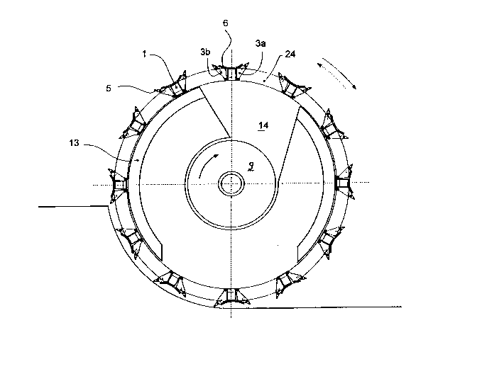
10 According to Fig. 1 the basic body of the cutting drum of an open pit
mining winning apparatus performing its winning action in both directions
of travel, automotive on a crawler type undercarriage, is formed by a
latticed drum. This latticed drum consists of cutting bars 1 evenly spaced
on the drum circumference and interconnected by rings 2. The cutter bars
15 1 are of rectangular cross-section and accommodate the cutting tools 3.
These cutting tools 3 consist of the pick holders 4, the picks 5, the sheet
metal scrapers 6, merging into blades 7 in the region of the pick tips and
the contact surface 8.
According to Fig. 5 the basic structure of the cutting drum further
20 includes the rings 9 terminating at the end face and comprising the ball
bearings 10, and the
toothed wheel rim 11 driven by the pinion 12. Inside the cutting drum the
annular chute 13 as well as the discharge chute 14 are provided.
The cutting drum is able to operate productively in both directions of
25 rotation. In Fig. 1 the momentary direction of rotation, duly observing the
21 92523
.
pick position resulting therefrom, is marked by an arrow pointing in the
right-hand direction.
According to the working example, the design of the cutting tools 3 may
be in accordance with two embodiments. The first embodiment according
5 to Figure 2 is at the same time the preferred embodiment while the
second embodiment according to Figure 3 represents a further
constructional possibility of the special embodiment.
Both embodiments have in common that the cutter bars 1 comprise lugs
on the edges oriented towards the rotation center of the cutting drum.
10 Each of the lugs 15 is provided with a bore 16, wherein the pick holders
4 by means of bolts 17 are held in an articulated manner. The pick
holders 4 can pivot within a range of about 10. The one terminal
position which at the same time is the operational position of the cutting
tool 3, is attained if, in embodiment 1, the pick holders 4 or in
15 embodiment 2, the blade 7 by way of the contact surface 8 bear(s)
against the cutter bar 1. The other terminal position is attained when the
cutter tool 3 is at an angle projecting into the already excavated region. In
the working example this position means that the pick holder 4 swings
away from the cutter bar 1 by approximately 10. As only one cutter tool
20 3a of a pair is in operational position (excavation position) at any one
time, depending on the rotational direction of the cutting drum, while the
other cutter tool 3b has to be swivelled into the already excavated
position, a connection bar 18 is provided between both pick holders 4a
and 4b. For fixing the cutter tools 3 of a pair 3a and 3b in the operational
25 position, depending on the rotational direction, even when moving
beyond the excavation region, a spring-loaded lever 19 comprising a roll
20 is disposed on one of the pick holders 4a or 4b, engaging a two-stage
latching means 21 provided on the outer surface of the cutter bar 1.
2 1 q2~23
-
The cutter tools 3 of both embodiments according to Figures 2 and 3
differ from one another in that in the preferred embodiment according to
Fig. 2 the contact surface 8 in relation to the cutter bar 1 is kept very
small so as to avoid build-up of conveyed material caught there between
S causing possible operational malfunctions. The embodiment according to
Fig. 3 comprises a backing plate of sheet metal connecting the pick
holders 4 and bearing against the cutter bar 1 in the operating position.
This solution offers better rigidity but may in practice result in operational
malfunctions, should the material to be mined be inclined to build-up on
10 the surfaces of the cutter bars 1 and the backing plate of sheet metal 22.
Both cutters 5c, each provided at the end of one of a helical line 23
connecting the pick tips and intended to cut free the end faces of the
cutting drum, are fitted to the pick holders 4c, deflected sideways at right
angles as shown in Fig. 5. Each cutter tool 3 includes two or more pick
15 holders 4 armed with picks 5. On each of the cutter bars 1 extending
over the entire width of the cutting drum and provided preferably parallel
to the rotational axis of the cutting drum, the cutter tools 3 are so
disposed that the picks 5 are evenly distributed. The invention provides
that the cutter tools 3 be designed to include two or more pick holders 4
20 and picks 5. In the working example according to Fig. 4 cutter tools 3
comprising two and three pick holders 4 are provided. From this
illustration it is further readily apparent that the pick holders 4 on
opposite sides of each cutter bar 1, are interconnected in an articulated
manner by one or a plurality of connecting bars 18. The length of these
25 connecting bars 18 is so chosen that, in the event of the cutter tool 3a
performing excavation work bearing against the cutter bar 1, the opposite
cutter tool 3b is raised to such an extent that its picks 5 are within the
cut-free outlines. This is the case when raised by about 10 (Figures 2
30 and 3)
2 1 92523
The bars 24, each disposed centrally between two rows of picks 5,
interconnect the cutter bars 1 rigidly and likewise form helical lines 23.
The blades 7 illustrated in Figures 2 and 3 may be advanced more or less
closely to the cutting orbit defined by the pick tips, depending on the
5 extent to which they are to participate in the excavation work. In the
case of coalescing strata, the blades 7 may be advanced very closely to
the cutting orbit. In the case of very easily excavated strata, picks 5 may
be dispensed with altogether, the blades 7 performing the excavating
task on their own. In very hard rock a gap, as illustrated in Figures 2 and
10 3, is provided between the cutting orbit and the blade 7. This causes the
blades 7 to break only the ridges remaining between the grooves (cut in
the rock by the picks 5) and to pick up most of the loosened material to
be mined. A small remainder, a few centimetres thick, is left on the
ground and is picked up during the next winning trip.
15 Conical sheet metal plates 25 form part of the basic structure of the
cutting drum according to Fig. 5. Their end facing outer edges are
particularly subjected to wear and tear during mining. Special edge
protection is therefore provided. According to Fig. 6 slots 27 are cut into
the conical sheet metal plates 25. Into these slots 27 hard metal discs
20 26 are soldered. This edge protection as well as the picks 4c of deflected
configuration, ensure that during excavation favourable conditions exist
even at the far ends of the cutting drum.
The claims which follow are to be considered an integral part of the
present disclosure. Reference numbers (directed to the drawings) shown
25 in the claims serve to facilitate the correlation of integers of the claims
with illustrated features of the preferred embodiment(s), but are not
intended to restrict in any way the language of the claims to what is
shown in the drawings, unless the contrary is clearly apparent from the
context.
30 What we claim is: -
1()