Some of the information on this Web page has been provided by external sources. The Government of Canada is not responsible for the accuracy, reliability or currency of the information supplied by external sources. Users wishing to rely upon this information should consult directly with the source of the information. Content provided by external sources is not subject to official languages, privacy and accessibility requirements.
Any discrepancies in the text and image of the Claims and Abstract are due to differing posting times. Text of the Claims and Abstract are posted:
| (12) Patent Application: | (11) CA 2192872 |
|---|---|
| (54) English Title: | HUB BRAKE FOR BICYCLES |
| (54) French Title: | FREIN A MOYEU POUR BICYCLETTES |
| Status: | Deemed Abandoned and Beyond the Period of Reinstatement - Pending Response to Notice of Disregarded Communication |
| (51) International Patent Classification (IPC): |
|
|---|---|
| (72) Inventors : |
|
| (73) Owners : |
|
| (71) Applicants : |
|
| (74) Agent: | MARKS & CLERK |
| (74) Associate agent: | |
| (45) Issued: | |
| (22) Filed Date: | 1996-12-13 |
| (41) Open to Public Inspection: | 1997-07-18 |
| Examination requested: | 1999-03-10 |
| Availability of licence: | N/A |
| Dedicated to the Public: | N/A |
| (25) Language of filing: | English |
| Patent Cooperation Treaty (PCT): | No |
|---|
| (30) Application Priority Data: | ||||||
|---|---|---|---|---|---|---|
|
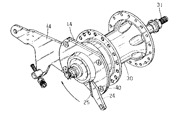
A hub brake for bicycles including a cylindrical hub
in which is fitted a screw rod extending therethrough, a
driving device including a driving screw, a bearing, an
adjusting nut, a bearing and an arm, a recovering device
including a torsion spring, a helical spring and a nut,
and a braking device including a brake block and a
positioning plate, and a cover fixedly mounted on the
positioning plate, whereby the hub brake for bicycles can
effectively reduce speed or stopping motion of a bicycle.
Note: Claims are shown in the official language in which they were submitted.
Note: Descriptions are shown in the official language in which they were submitted.
2024-08-01:As part of the Next Generation Patents (NGP) transition, the Canadian Patents Database (CPD) now contains a more detailed Event History, which replicates the Event Log of our new back-office solution.
Please note that "Inactive:" events refers to events no longer in use in our new back-office solution.
For a clearer understanding of the status of the application/patent presented on this page, the site Disclaimer , as well as the definitions for Patent , Event History , Maintenance Fee and Payment History should be consulted.
| Description | Date |
|---|---|
| Inactive: IPC deactivated | 2012-01-07 |
| Inactive: IPC from PCS | 2012-01-01 |
| Inactive: IPC expired | 2012-01-01 |
| Inactive: IPC from MCD | 2006-03-12 |
| Inactive: IPC from MCD | 2006-03-12 |
| Inactive: IPC from MCD | 2006-03-12 |
| Time Limit for Reversal Expired | 2000-12-13 |
| Application Not Reinstated by Deadline | 2000-12-13 |
| Deemed Abandoned - Failure to Respond to Maintenance Fee Notice | 1999-12-13 |
| Letter Sent | 1999-04-09 |
| Inactive: Status info is complete as of Log entry date | 1999-04-09 |
| Inactive: Application prosecuted on TS as of Log entry date | 1999-04-09 |
| Request for Examination Requirements Determined Compliant | 1999-03-10 |
| All Requirements for Examination Determined Compliant | 1999-03-10 |
| Application Published (Open to Public Inspection) | 1997-07-18 |
| Abandonment Date | Reason | Reinstatement Date |
|---|---|---|
| 1999-12-13 |
The last payment was received on 1998-10-22
Note : If the full payment has not been received on or before the date indicated, a further fee may be required which may be one of the following
Please refer to the CIPO Patent Fees web page to see all current fee amounts.
| Fee Type | Anniversary Year | Due Date | Paid Date |
|---|---|---|---|
| MF (application, 2nd anniv.) - small | 02 | 1998-12-14 | 1998-10-22 |
| Request for examination - small | 1999-03-10 |
Note: Records showing the ownership history in alphabetical order.
| Current Owners on Record |
|---|
| VALISUM INDUSTRIES LTD. |
| Past Owners on Record |
|---|
| I-TAI LAI |

