Language selection

Search

Patent 2192914 Summary

Third-party information liability

Some of the information on this Web page has been provided by external sources. The Government of Canada is not responsible for the accuracy, reliability or currency of the information supplied by external sources. Users wishing to rely upon this information should consult directly with the source of the information. Content provided by external sources is not subject to official languages, privacy and accessibility requirements.

Claims and Abstract availability

Any discrepancies in the text and image of the Claims and Abstract are due to differing posting times. Text of the Claims and Abstract are posted:

  • At the time the application is open to public inspection;
  • At the time of issue of the patent (grant).
(12) Patent Application: (11) CA 2192914
(54) English Title: QUADRATIC STORAGE CONTAINER
(54) French Title: RECIPIENT DE STOCKAGE QUADRATIQUE
Status: Deemed Abandoned and Beyond the Period of Reinstatement - Pending Response to Notice of Disregarded Communication
Bibliographic Data
(51) International Patent Classification (IPC):
  • A61J 01/05 (2006.01)
  • B01L 09/00 (2006.01)
  • G01N 37/00 (2006.01)
(72) Inventors :
  • AMELUNG, ROLF (Germany)
(73) Owners :
  • HEINRICH AMELUNG GMBH
  • HEINRICH AMELUNG GMBH
(71) Applicants :
  • HEINRICH AMELUNG GMBH (Germany)
  • HEINRICH AMELUNG GMBH (Germany)
(74) Agent: SMART & BIGGAR LP
(74) Associate agent:
(45) Issued:
(22) Filed Date: 1996-12-13
(41) Open to Public Inspection: 1997-06-16
Examination requested: 2001-09-20
Availability of licence: N/A
Dedicated to the Public: N/A
(25) Language of filing: English

Patent Cooperation Treaty (PCT): No

(30) Application Priority Data:
Application No. Country/Territory Date
195 46 894.5 (Germany) 1995-12-15

Abstracts

English Abstract


1. Quadratic storage container.
2.1 It is known to cover the inlet openings of measuring
vessels for analyzing blood, plasma or the like, with
which a storage container of this type is furnished, with
a foil in order to protect them against contamination.
When removing the foil, however, dust lying on the foil
can be pushed off, said dust then falling into the
measuring vessels and thus affecting the measurement
results. It is the object of the invention to design a
storage container in such a way that the functionability
of the measuring vessels is fully maintained in every
case.
2.2 To accomplish this, it is provided that openings (4, 5)
which serve to guide an ejector rack (2) and are provided
on the upper side (8) of the storage container, are
arranged laterally outside of the covering area of the
measuring vessels (6).
2.3 Since the measuring vessels are hereby fully covered by
the upper side (8) of the storage container (1), the use
of a foil having the aforementioned disadvantages is no
longer necessary.
3. Fig. 1.


Claims

Note: Claims are shown in the official language in which they were submitted.

Claims
1. Quadratic storage container which has openings in which
an ejector rack can be guided, through which measuring
vessels arranged in rows can be shifted in an ejection
slot on the front end for receiving liquids to be
analyzed, such as blood, plasma or the like, whereby a
sliding bar abutting the ejector rack is situated between
the last row of the measuring vessels facing away from
the ejection slot and the rear wall of the storage
container, characterized therein that the openings (4, 5)
are laterally situated outside of the covering area of
the measuring vessels (6).
2. Storage container according to claim 1, characterized
therein that the openings (5, 6) are provided in the
outermost peripheral area of the upper side (8) and rear
side, adjacent to the opposite front ends.
3. Storage container according to claim 1, characterized
therein that the openings are provided only in the area
of the rear narrow side.

Description

Note: Descriptions are shown in the official language in which they were submitted.


219291~
Description
Quadratic 8torage Container
The present invention concerns a quadratic storage container
according to the preamble of claim 1.
A storage container of this type is known from DE-GM 92 02
381.
In principle, the storage container shown and described there
has proved successful. However, problems could arise when
using the covering foil in that dust collects on it,
especially during a longer storage time, in the area of the
openings, and said dust is pushed off when the foil is pulled
out, can fall into the measuring vessel and thus affect the
measurement result in certain circumstances.
Moreover, when the measuring vessels are furnished with balls,
static charges on the foil could lead thereto that these balls
are pulled out of the measuring vessels, so that they are no
longer suitable for the intended testing which could then
result in equipment breakdowns.
The side walls of the known storage container are
ultrasonically welded together after it has been filled with
measuring vessels and covered with the foil. In this case,
the danger arises that the foil is also heat-sealed with the
walls of the storage container, so that a flawless and easy
removal of the foil is then not assured in every case.
The object of the present invention is to design a storage

2~92914
-- 2 --
._
container of this type in such a way that a contamination of
the measuring vessels is ruled out and its use assured in
every case without restrictions.
This object is solved by a storage container which has the
features of claim 1.
As a result of this structural form, the inlet openings of all
of the measuring vessels can now be completely covered by the
upper housing side of the storage container, so that the
function of the known foil is now assumed by the allocated
broadside of the storage container.
In view of the fact that the inlet openings of the measuring
vessels are not open at any time until they are used in an
automatic testing machine, it is also not possible that dust
which has collected on the cover can get into the measuring
vessels.
The testing accuracy or the reliability of the measurement is
thereby considerably improved.
Due to the missing foil, a static charge of the measuring
vessels is also ruled out, so that problems no longer occur
during measurement as a result of the balls pulled out (as
described).
The disadvantages resulting from heat-sealing the foil are
also ruled out since, as noted, the use of a foil can be omitted.
Naturally, this is also associated with a saving in costs
resulting, on the one hand, from the manufacture of the foil

_ 3 _ 2 1 92 9 1 4
and, on the other hand, from the disposal thereof.
According to an advantageous embodiment of the invention, it
is provided that the openings are arranged on the broadside
forming the upper side of the storage container, that is in
the peripheral areas adjoining the front end and partially in
continuation in the rear area.
The openings on the rear are thereby measured in their length
such that the sliding bar is securely carried along by the
prongs of the ejector rack.
According to a further idea of the invention, it is provided
that openings are only placed on the back through which the
prongs of the ejector rack are pressed against the sliding
bar.
In principle, the storage container is then sealed on all
sides with the exception of the rear openings and the ejector
slot on the front.
Further advantageous embodiments of the invention are
characterized in the sublcaims.
An example of an embodiment of the invention shall be
described in the following with reference to the attached
drawings, showing:
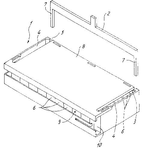
igure 1 a storage container according to the invention in a
perspective view,
igure 2 a storage container in a rear view.

_ 4 _ 2~ 92 914
-
The quadratic storage container 1 shown in the figures is
furnished with a number of measuring vessels 6 which are also
quadratic, arranged in rows and adjacent to one another in the
storage container 1, and which are used to receive liquids to
be analyzed, such as blood, plasma or the like.
Two slot-like openings 4, extending diagonally to the
longitudinal axis, spaced and parallel to one another, are
provided in a broadside forming the upper side 8 of the
storage container 1. These are placed adjacent to one another
in the immediate peripheral area of the upper side 8 of the
respective front end of the storage container 1 and extend
into the rear area where they also form slot-like openings 5.
Prongs 7 of an ejector rack 2 can be guided in these openings
4, 5, said prongs thereby abutting against a sliding bar 3
which extends in the direction of the longitudinal axis of the
storage container 1 over the entire length of a longitudinal
row of measuring vessels 6, whereby the sliding bar 3 is
situated between the rear of the storage container 1 and the
last row of measuring vessels 6.
The inlet openings of the measuring vessels 6, aligned toward
the upper side 8, are completely covered by the upper side 8,
i.e. the openings 4, 5 are located outside of the range of
coverage.
Instead of openings 4, 5, openings can be provided in the rear
of the storage container 1 through which appropriately formed
prongs of an ejector rack or a similar device cna be guided
and shift the measuring vessels 6 by means of the sliding bar
3 in direction of an ejection slot 9. The latter is situated

2 1 929 1 4
-- 5
on the front and provided, on the front side of the storage
container 1, with an opening 10 through which the measuring
vessels 6 can exit individually and be conveyed to an
automatic testing unit.
List of Reference Numbers
1 Storage container
2 Ejector rack
3 Sliding bar
4 Opening
Opening
6 Measuring vessel
7 Prongs
8 Upper side
9 Ejection slot

Representative Drawing
A single figure which represents the drawing illustrating the invention.
Administrative Status

2024-08-01:As part of the Next Generation Patents (NGP) transition, the Canadian Patents Database (CPD) now contains a more detailed Event History, which replicates the Event Log of our new back-office solution.

Please note that "Inactive:" events refers to events no longer in use in our new back-office solution.

For a clearer understanding of the status of the application/patent presented on this page, the site Disclaimer , as well as the definitions for Patent , Event History , Maintenance Fee  and Payment History  should be consulted.

Event History

Description Date
Inactive: IPC from MCD 2006-03-12
Application Not Reinstated by Deadline 2002-12-13
Time Limit for Reversal Expired 2002-12-13
Deemed Abandoned - Failure to Respond to Maintenance Fee Notice 2001-12-13
Letter Sent 2001-10-09
Inactive: Application prosecuted on TS as of Log entry date 2001-10-09
Inactive: Status info is complete as of Log entry date 2001-10-09
Request for Examination Requirements Determined Compliant 2001-09-20
All Requirements for Examination Determined Compliant 2001-09-20
Application Published (Open to Public Inspection) 1997-06-16

Abandonment History

Abandonment Date Reason Reinstatement Date
2001-12-13

Maintenance Fee

The last payment was received on 2000-11-23

Note : If the full payment has not been received on or before the date indicated, a further fee may be required which may be one of the following

  • the reinstatement fee;
  • the late payment fee; or
  • additional fee to reverse deemed expiry.

Patent fees are adjusted on the 1st of January every year. The amounts above are the current amounts if received by December 31 of the current year.
Please refer to the CIPO Patent Fees web page to see all current fee amounts.

Fee History

Fee Type Anniversary Year Due Date Paid Date
Registration of a document 1997-02-26
MF (application, 2nd anniv.) - standard 02 1998-12-14 1998-11-19
MF (application, 3rd anniv.) - standard 03 1999-12-13 1999-11-24
MF (application, 4th anniv.) - standard 04 2000-12-13 2000-11-23
Request for examination - standard 2001-09-20
Owners on Record

Note: Records showing the ownership history in alphabetical order.

Current Owners on Record
HEINRICH AMELUNG GMBH
Past Owners on Record
ROLF AMELUNG
Past Owners that do not appear in the "Owners on Record" listing will appear in other documentation within the application.
Documents

To view selected files, please enter reCAPTCHA code :


To view images, click a link in the Document Description column. To download the documents, select one or more checkboxes in the first column and then click the "Download Selected in PDF format (Zip Archive)" or the "Download Selected as Single PDF" button.

List of published and non-published patent-specific documents on the CPD .

If you have any difficulty accessing content, you can call the Client Service Centre at 1-866-997-1936 or send them an e-mail at CIPO Client Service Centre.


Document
Description 
Date
(yyyy-mm-dd) 
Number of pages   Size of Image (KB) 
Representative drawing 1997-08-14 1 17
Abstract 1997-04-17 1 27
Description 1997-04-17 5 149
Drawings 1997-04-17 1 22
Claims 1997-04-17 1 27
Reminder of maintenance fee due 1998-08-16 1 115
Reminder - Request for Examination 2001-08-13 1 129
Acknowledgement of Request for Examination 2001-10-08 1 194
Courtesy - Abandonment Letter (Maintenance Fee) 2002-01-09 1 182
Prosecution correspondence 2001-09-19 1 48
Correspondence 1997-01-27 1 36