Language selection

Search

Patent 2193148 Summary

Third-party information liability

Some of the information on this Web page has been provided by external sources. The Government of Canada is not responsible for the accuracy, reliability or currency of the information supplied by external sources. Users wishing to rely upon this information should consult directly with the source of the information. Content provided by external sources is not subject to official languages, privacy and accessibility requirements.

Claims and Abstract availability

Any discrepancies in the text and image of the Claims and Abstract are due to differing posting times. Text of the Claims and Abstract are posted:

  • At the time the application is open to public inspection;
  • At the time of issue of the patent (grant).
(12) Patent: (11) CA 2193148
(54) English Title: CARRIER BOX
(54) French Title: BOITE DE TRANSPORT
Status: Expired and beyond the Period of Reversal
Bibliographic Data
(51) International Patent Classification (IPC):
  • B65D 5/46 (2006.01)
  • B65D 5/475 (2006.01)
(72) Inventors :
  • DELISLE, ALAIN (Canada)
  • DELISLE, CHARLES (Canada)
  • ZAMPINI, GERRY (Canada)
(73) Owners :
  • ROLLAND INC.
(71) Applicants :
  • ROLLAND INC. (Canada)
(74) Agent: SWABEY OGILVY RENAULT
(74) Associate agent:
(45) Issued: 2000-04-18
(22) Filed Date: 1996-12-17
(41) Open to Public Inspection: 1998-06-17
Examination requested: 1997-04-23
Availability of licence: N/A
Dedicated to the Public: N/A
(25) Language of filing: English

Patent Cooperation Treaty (PCT): No

(30) Application Priority Data: None

Abstracts

English Abstract


A container for printer paper or the like formed of a
rectangular bottom part containing the paper and a rectangular cover having
peripheral flanging which enables the cover to fit exactly over the bottom
part. The cover is formed with a deformable band which is integral with the
material of the cover and constitutes the handle of the container. To prevent
any damage to the handle while carrying the carrier box, a reinforcing belt
is wrapped around the bottom part and cover while remaining in contact
with the band.


Claims

Note: Claims are shown in the official language in which they were submitted.

The embodiments of the invention, in which an exclusive property or
privilege is claimed are defined as follows:
1. Container for printer paper or the like, which
comprises a rectangular bottom part to contain said paper, a rectangular
cover having means defining peripheral flanges enabling to fit said cover
over said bottom part, said cover formed with means defining a deformable
band which is integral with the material of said cover and can be used to
constitute a handle for said container, and a reinforcing belt to wrap around
said bottom part and said cover over said band when said cover is in
position over said bottom part, and means enabling said reinforcing belt to
follow and remain in substantial contact with said band when said band is
formed into said handle.
2. Container according to claim 1, wherein at least said
cover is made of cardboard.
3. Container according to claim 1, wherein said bottom
part and said cover are both made of cardboard.
4. Container according to claim 1, wherein said cover
comprises a substantially rectangular blank having flange-forming folding
lines provided therein.
5. Container according to claim 5, wherein said flange-forming
folding lines are placed on said blank to coincide with upper edges
of said cover.

6. Container according to claim 5, wherein a first pair of
said folding lines which are parallel to one another extend all the way from
one side of said blank to the opposite side thereof.
7. Container according to claim 6, wherein said blank
comprises slots which extend from said first pair of flange-forming folding
lines to the remaining sides of said rectangular blank, a second pair of said
folding lines being provided parallel to one another and perpendicular to
said first pair of folding lines, said slots being in the continuation of said
second pair of said folding lines, said slots-defining folding tabs at all
corners of said rectangular blanks.
8. Container according to claim 7, wherein said cover is
formed by downwardly folding flange portions between said tabs along said
first flange-forming folding lines, folding along said second flange-forming
folding lines, and finally folding said tabs against said flange portions.
9. Container according to claim 8, wherein said blank
additionally comprises a first pair of transverse parallel cuts which extend
all the way between a pair of said flange-forming folding lines to form said
band and past them sufficiently to enable said band to arch upwardly when
being pulled, thereby forming said handle.
10. Container according to claim 9, wherein said first pair
of transverse parallel cuts are formed between said first pair of
flange-forming folding lines.

11. Container according to claim 9, wherein said cover
comprises an intermediate folding line parallel to and disposed between said
cuts and flange-forming folding lines parallel thereto and second cuts which
extend from the ends of said intermediate folding lines and extend to said
first cuts, thereby defining downwardly foldable flaps enabling to grab said
handle.
12. Container according to claim 11, which comprises a
reinforcing tape applied against the under face of said handle.
13. Container according to claim 12, wherein said belt is
made of plastic material.

Description

Note: Descriptions are shown in the official language in which they were submitted.


2193148
This invention relates to a carrier box. More particularly, the
present invention is concerned with a container for printer paper or the like
w_ich is provided with handle means enabling to easily carry the box from
one location to another.
The development of the computer has given rise to an
enormous consumption of paper which is customarily stored in small
cardboard boxes. Now, it is quite normal to carry these boxes from one
location to another, generally by grabbing the entire box and to hand carry it
to a chosen place. Of course, all sorts of means to facilitate the h~n~ling of
1 o these boxes. However, to this date, the art has not suggested something that
is inexpensive, easy to produce and convenient to use in hAnllling carrier
boxes, especially those that are utilized to contain printer paper.
U.S. 2,880,866 issued April 7, 1959 to W.J. Van Dyck
discloses a shipping package for paper, which however has no means to
handle it.
U.S. 3,012,660 issued December 12, 1961, inventor Water T.
Sheldon, Jr., relates to a shipping container including a prismatic body,
closure caps and a strap to secure the parts together.
U.S. 4,418,864 issued December 6, 1983, inventor John C.
Nielsen, describes a carton with handle which is made of a strip of
reinforcing tape which is secured to the side walls of the carton.
U.S. 4,567,070 issued January 28, 1986, inventor Thomas J.
Karass, is concerned with a container having a handle integral therewith and
a tape inserted between the layers of the box and also between those
2 5 forming the handle. Although giving some s~ fAction, this article is
complicated and expensive to mAmlf~cture.

21 931 '~
U.S. 4,817,866 issued April 4, 1989, inventor Roger J.
Wormacott, is another example of a tape incorporated into the material of
the box and of the handle to reinforce the latter.
Other pale~ of interest for storing sheet material including
5coll~puler forms.
It will be realized that there is a need for cheap container
which includes a reinforced handle.
It is an object of the present invention to provide a carrier box
which incorporates a reinforced handle that is easy to msmll~cture and
10cheap to produce.
It is another object of the present invention to provide a
container for printer paper which is built with an integrated handle and is
reinforced with a plastic belt wrapping the container including the handle
part.
5These and other objects of the invention may be achieved by
providing a container for printer paper or the like, which comprises a
rect~n~ r bottom part to contain the paper, a recl~n~ r cover having
means ~lçfining peripheral flanges enabling to fit the cover over the
rect~nglll~r bottom part. The cover is formed with cuts defining a
2 odeformable band which is integral with the material of the cover and can be
used to con~tit~lte a handle for the container.
A reinforcing belt is provided to wrap around the bottom part,
and the cover over the band when the cover is in position over the bottom
part. Means are provided to enable the reinforcing belt to follow and remain
2 5in substantial contact with the band when the latter is formed into a handle.The invention is illustrated but is not limited by the annexed
drawings which show a preferred embodiment and in which:

;~1 931 4~
--3--
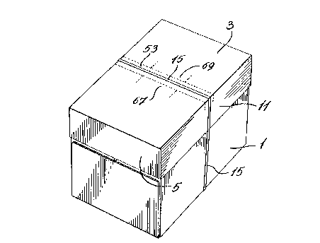
FIGURE 1 is a perspective view of a carrier box according to
the invention, provided with a wrapping belt;
FIGURE 2 is a partial perspective view showing the carrier
box being grabbed by the handle;
5FIGURE 3 is a view of a blank which may be used to
m~mlf~cture the cover of a carrier box according to the invention;
FIGURE 4 is a transverse cross-section view through the
carrier box illustrated in FIGURE l;
FIGURE S is a partial cross-section view showing the handle
10and belt in raised position and the flaps in depressed position; and
FIGURE 6 is a cross-section view of the handle portion in
storage position of the carrier box, taken along line 6-6 of FIGURE 3.
With reference to the drawings, it will be seen that the carrier
box according to the invention is especially designed as a container for
5printer paper or the like, and is entirely made of cardboard. Of course, the
carrier box may be designed for other purpose, i.e. to contain any type of
product and may be made of any kind of m~tçri7.17 such as plastic.
As illustrated, the carrier box essentially consists of a
rect~nglll~r bottom part 1, which is designed to contain printer paper, a
20rect~ng~ r paper 3 formed with flanges S, 7, 9 and 11, a handle 13 and a
wrapping belt 15. As shown, the flanges are folded as will be discussed
later so as to enable the cover to fit exactly over bottom part 1.
In the embodiment illustrated, both the bottom part 1 and
cover 3 are made of cardboard although, as discussed previously, any other
25type of m~t~ l could be used. Handle 13 is integral with the m~t~ 1 of
cover 3 as will be discussed later.
Cover 3 is made from a substantially rectangular blank A as
particularly in Figure 3. Blank A is formed with a first set of flange-forming

- ~ 931 48
-
-4-
folding lines 17,19 which are parallel to one another and extend all the way
from one side of the blank to the opposite side thereof. The blank also
comprises slots 21, 23, 25 and 27 which, as shown, extend from respective
folding lines 17,19 to other sides of the blank. In addition, a second pair of
flange-forming folding lines 29,31, which are parallel to one another are
perpendicular to folding lines 17,19, are provided so that slots 21,25 and
23,27 are in the respective continl~tion of folding lines 29,31. To facilitate
the production of cover 3, blank 1 has four cut-out portions at the corners
thereof so that each tab 33, 35, 37 and 39 formed by folding along flange-
0 forming folding lines 17,19, will have an angular edge 41, 43, 45 and 47.
It will therefore be realized that, to form cover 3 of the carrier
box according to the invention, flanges 7 and 11 are first folded
dowllw~dly along flange-forming folding lines 29,31, respectively. Tabs
33, 35, 37 and 39 are then folded inwardly. This is followed by a downward
folding of flanges 5 and 9 along folding lines 17,19 and finally adhesively
combining tabs 33,39 and 35,37 respectively against the inner faces of tabs
5 and 9.
The blank additionally comprises a pair of transverse parallel
cuts 49,51 which extend all the way between folding lines 29,31 and past
2 o these two folding lines as shown in Figure 3, sufficiently to enable band 53
which is formed to arch upwardly as shown in Figures 2 and 5 when being
pulled, thereby formillg handle 13.
Blank A additionally comprises intermediate folding lines
55,57 which, as shown in Figure 3, are located intermediate between cut 49
and folding line 17 and cut 51 and folding 19, respectively. The ends of
folding lines 55,57 are connected to cuts 49,51 respectively by means of
cuts 59, 61, 63 and 65. It will be seen, with particular rererellce to Figure 5,that these intermediate folding lines and secondary cuts will form tabs 67,69

~1~3148
' - -s-
which can be pushed duwllw~dly as shown in Figure S while the band 53 is
pulled u~wardly to form handle 13.
When the cover is formed from blank ~, it is placed over
bottom part 1 and belt 15 is fixedly wrapped around the box to cover the top
5 surface of band 53, as particularly shown in Figure 1. To provide for a
stronger handle, its inner face is adhesively covered with a reinforcing tape
71. Anyone skilled in the art would know the material to be used to
m~mlf~cture belt 13 and reinforcing tape 71.

Representative Drawing
A single figure which represents the drawing illustrating the invention.
Administrative Status

2024-08-01:As part of the Next Generation Patents (NGP) transition, the Canadian Patents Database (CPD) now contains a more detailed Event History, which replicates the Event Log of our new back-office solution.

Please note that "Inactive:" events refers to events no longer in use in our new back-office solution.

For a clearer understanding of the status of the application/patent presented on this page, the site Disclaimer , as well as the definitions for Patent , Event History , Maintenance Fee  and Payment History  should be consulted.

Event History

Description Date
Time Limit for Reversal Expired 2001-12-17
Letter Sent 2000-12-18
Grant by Issuance 2000-04-18
Inactive: Cover page published 2000-04-17
Amendment Received - Voluntary Amendment 2000-02-08
Inactive: Final fee received 1999-11-03
Pre-grant 1999-11-03
Notice of Allowance is Issued 1999-05-06
Letter Sent 1999-05-06
Inactive: Approved for allowance (AFA) 1999-04-22
Amendment Received - Voluntary Amendment 1999-01-21
Application Published (Open to Public Inspection) 1998-06-17
Inactive: Application prosecuted on TS as of Log entry date 1997-08-04
Letter Sent 1997-08-04
Inactive: Status info is complete as of Log entry date 1997-08-04
Request for Examination Requirements Determined Compliant 1997-04-23
All Requirements for Examination Determined Compliant 1997-04-23

Abandonment History

There is no abandonment history.

Maintenance Fee

The last payment was received on 1999-12-17

Note : If the full payment has not been received on or before the date indicated, a further fee may be required which may be one of the following

  • the reinstatement fee;
  • the late payment fee; or
  • additional fee to reverse deemed expiry.

Please refer to the CIPO Patent Fees web page to see all current fee amounts.

Fee History

Fee Type Anniversary Year Due Date Paid Date
Request for examination - standard 1997-04-23
MF (application, 2nd anniv.) - standard 02 1998-12-17 1998-11-25
Final fee - standard 1999-11-03
MF (application, 3rd anniv.) - standard 03 1999-12-17 1999-12-17
Owners on Record

Note: Records showing the ownership history in alphabetical order.

Current Owners on Record
ROLLAND INC.
Past Owners on Record
ALAIN DELISLE
CHARLES DELISLE
GERRY ZAMPINI
Past Owners that do not appear in the "Owners on Record" listing will appear in other documentation within the application.
Documents

To view selected files, please enter reCAPTCHA code :


To view images, click a link in the Document Description column. To download the documents, select one or more checkboxes in the first column and then click the "Download Selected in PDF format (Zip Archive)" or the "Download Selected as Single PDF" button.

List of published and non-published patent-specific documents on the CPD .

If you have any difficulty accessing content, you can call the Client Service Centre at 1-866-997-1936 or send them an e-mail at CIPO Client Service Centre.


Document
Description 
Date
(yyyy-mm-dd) 
Number of pages   Size of Image (KB) 
Abstract 1997-04-21 1 13
Description 1997-04-21 5 187
Drawings 1997-04-21 3 84
Claims 1997-04-21 3 83
Cover Page 1997-04-21 1 16
Cover Page 1998-06-17 1 38
Abstract 2000-02-08 1 16
Cover Page 2000-03-02 1 32
Representative drawing 1998-06-17 1 8
Representative drawing 2000-02-09 1 7
Representative drawing 2000-03-02 1 11
Acknowledgement of Request for Examination 1997-08-04 1 178
Reminder of maintenance fee due 1998-08-18 1 115
Commissioner's Notice - Application Found Allowable 1999-05-06 1 164
Maintenance Fee Notice 2001-01-15 1 178
Correspondence 1999-11-03 2 51
Correspondence 2000-02-08 2 52
Fees 1999-12-17 1 40