Note: Descriptions are shown in the official language in which they were submitted.
~ W096/02022 ~I/ZJ~ ~
21 9~t'~
Image-Receiving Film ~or Electrography
The present invention relates to an image-receiv-ng
film for electrography. More particularly, it relates to
a film useful for receiving an image formed by
electrography.
The term "electrography" used herein is intended to
mean systems including electrophotography,
electroradiography and magnetography, as widely
recognized in the field of imaging and described in a
nu~ber of patent documents and the like. The image-
receiving film of the present invention can be useful:y
utilized for the preparation of an OHP film particularly
by color electrophotography among the electrographic
systems.
In recent years, various electronic equipment
manufacturers have put electrophotographic full-color
copying machines on the market. In fact, the advance of
fuil-color electrophotographic techniques in recent ;ears
is significant, and even copying ~nhin~, which can
reproduce images having a quality close to printed
matters or photographic prints, have now appeared. In
tr.e OHP films, however, there are problems to be solved.
A particularly serious problem is as follows. In orcer
to avoid the occurrence of the so-called "offset
ph~nn~Pnnn," that is, the transfer of a toner on a
fixation roller at the time of fixation of an image
transferred onto an OHP film, a silicone oil is coated on
the surface of the fi~ation roller, which unfavorably
causes the surface of the OHP film to become oily. This
problem is attributable to such a phenomenon that parl of :~
tr.e silicone oil coated on the surface of the fixaticn
roller is transferred from the surface onto the film.
Further, when the oily film, as such, is inser~ed
into a sleeve or a cover utilized for protection and
s~orage of the OHP film, for example, Flip-Frame~
_ _ _ _ _ _ _ _ _ _ _ _ _ _
W096/02022 r~
(registered trade mark) manufactured by 3M, U.S.A.,
particularly when the amount of the oil transferred to
the film is large, the migration and accumulation of the
oil (the so-called "oil pooling") occurs in a region
where the film is in contact with the sleeve. The oil
pooling is projected as a large eyesore at the time o
projection of the OHP film. For this reason, the
development of a technique for reducing the oiliness or
oily feeling and removing the oil pooling has been
desired in the field of OHP films.
In order to reduce the oiliness of the OHP film
attributable to the use of a silicone oil, Japanese
Un~Y~m-ned Patent Publicatlon (Kokai) No. 5-173351
proposes an OHP film comprising a recording layer (ar.
image-forming layer) having a capabllity of absorbing a
silicone oil. The recording layer is composed mainly of
a polymethacrylic ester/styrene copolymer (hydroxyl
number: 40 or more) and a polymer of a quaternary
ammonium salt. However, as-is apparent from Comparative
Example 3, which will be described later, the capability
of this film to absorb the silicone oil still remains low
even when the hydroxyl number of the polymethacrylic
ester/styrene copolymer used in the recording layer s
80. Further, in such a film, although the adsorption of
the silicone oil at the time of contact with the fixation
roller is increased, the oil retention is so low tha~
there is a fear of the oil pooling ph~n~m~n~ becoming
severe. Furthermore, In the above film, the water
absorption of the recording layer is so high that there
is a fear of the recording layer absorbing moisture in
air, thereby causing the silicone oil absorption and the
image formability to be deteriorated with time.
Furthermore, in the film, the composition of the
recording layer is complicate, which unavoidably incurs
an increase in cost.
--2--
W096l02022 P~llu~ _-
~1!q3~'t'9'
In order to prevent the occurrence of oil pooling at
the time of contact of the OHP film with Flip-Frame~',
U.S. Patent No. 5,208,093 proposes to incorporate, into
' an image-receiving layer comprising a polymer film having
a thickness of 0.5 to 10 um, particles at least half of
which have a particle diameter enough to protrude from
the image-receiving layer (for example, silica particles
having a particle diameter of about 10 um). For example,
as shown in Fig. 5, this novel film comprises a substrate
11 comprising a transparent polyethylene terephthalate
film and, provided on said substrate, an image-receiving
layer 12 comprising a polyester resin containing silica
particles 15. ~he silicone oil from the fixation roller
is absorbed into the image-receiving layer 12 on its
surface to form an oil layer 17. When the film as shown
in the drawing is housed in Flip-Frame~ 18, the
occurrence of oil pooling can be effectively inhibited
because the particle diameter of the silica particles 15
is larger than the thickness of the image-receiving layer
12. Since, however, the thin oil layer provided on the
image-receiving layer is indispensable to this film, the
problem of the oiliness to the touch cannot be solved.
Accordingly, an object of the present invention lS
to provide an image-receiving film for electrography
which enables the occurrence of an oil pooling ph~n~r~n~n
to be minimi~ed (the inhibition of an oil pooling
ph~r ~n~n), the silicone oil once held on the image-
receiving layer to remain held without rapid falling (an
improvement in oil retention) and the transfer of the
silicone oil, when touched by hand, to be reduced (a
reduction in oiliness to the touch).
According to the present invention, the above-
described object of the present invention can be attained
by an imagereceiving film for electrography, comprising a
transparent substrate or support and an image-receiving
--3--
- ~/ 2793219
layer or receptor layer provided on at least one surface
of said substrate, wherein said image-receiving layer
contain5 at least one silicone oil adsorbent selected
- from the group consistinq of fatty acids, esters of fatty
S acids, derivatives of fatty acids and metallic soaps~
Furthcr, accard -~ to thc prc-cnt invcnt on, thc
~bove deacri~cd objcct can bc ~ttaincd by an imagc
rccciving film for clcctrography, e- ri~ing c
tran-parcnt ~ubotratc and an imagc rccciving lay~r
: 10 providcd on at lca3t onc surfacc of ~aid 3ub3tratc,
whcrcin 3aid :- ~c rccciving laycr contain_ at lca-t ono
3iliconc oil ad~or~cnt sclcctcd fr~- the ~.ou~ cor,3itting
polyhydric alcohols, higher alcohols and higher
dialcohols~ orL
~urthc ~rc, thc abovc-dc_cribcd objcct can bo
attaincd by an imagc-rccciv ng film for clcctrography,
e~..rri3ing a tran-parcnt sub_tratc or 3upport and an
imaqa Le_eiving layer or reccptor layer providcd on at
lca~t onc ~uriacc of acid ~ub~trctc, wl.~rein said image-
ho~q
receiving layer ha~Von its surface an overcoat layer, and
said overcoat layer cont~n~ at least one silicone oil
adsorbent selected from the group consisting of fatty
acids, esters of fatty acids, derivatives of fatty acids
and metallic soaps.
~u~l h9 ~~~0, th~ ~CVC ~criocd objcct Cl~ bc
attaincd by an imagc ~ccciving film for clcctrography,
c riaing a trar.~rrrcnt ~ub_tratc and an ~~gc-rcceiving
laycr providcc on at lca3t onc ~urfacc of aaid ~batrate,
uhcrcin ~aid im~gcreeciving laycr ha~ on it~ 3urf~cc an
ovcrcoat lcyer, and scid overccat layer .ontaills at least
onc _iliconc oil adoorbcnt aclcc~cd fr~ the g~oup
co-~icting of polyhydric alcohols, higher alcohols and
higher dialcohols ~h~ d ~ ~c~ O~ ~d~ ~ ~-Q~,
~Qt~ O~ O~O /s~ c.
In~the present invention, the overcoat layer
containing a silicone oil adsorbent may be provided on
_ 4 _ AMENDEl) SHEET
. , _ . . . . .. _ . ..... _ .
W096/02022 ~ 9 r~
the image-receiving layer directly or alternatively
through any intermediate layer. In general, the
thickness of the overcoat layer is preferably in the
range of from 0.01 to 10 g/m~ in terms of the coveraqe.
The construction and the mode of operation of the
image receiving film for electrography according to the
present invention will now be described in detail.
Fig. 1 is a schematic cross-sectional view of a
preferred embodiment of the image-receiving film
according to the present invention. In this image-
receiving film, an image-receiving layer 2 and an
overcoat layer 3 are successively provided on one sur-ace
of a transparent substrate 1. The overcoat layer 3
ccmprises a specific compound having a carboxyl group
(fatty acids, esters of fatty acids, derivatives of ~atty
acids and metallic soaps) or a specific compound hav ng a
hydroxyl group (polyhydric alcohols, higher alcohols and
higher dialcohols). In this embodiment, if necessar;,
tne image-receiving layer 2 and the overcoat layer 3 may
be provided also on the opposite side of the suostrale 1
although this is not shown in the drawing. Further, it
is also possible to interpose one or more additional
layers, for example, between the image-receiving layer 2
ar.d the overcoat layer 3 or on other positions, so far as
the additional layer is not detrimental to the effec_
contemplated in the present invention.
With respect to the transparent substrate, a
suitable transparent film may be properly selected f-om
plastic films commonly used as a substrate in the ar in
the production of an image-receiving film. The suitable
~ substrate is preferably a heat-resistant plastic film,
ar.d examples thereof include films of polyethylene
terephthalate, polyethylene naphthalate, polymethyl
acrylate, polymethyl methacrylate, cellulose triacetate,
plyamides, polyimides, polyvinyl chloride, polyvinyl:dene
--5--
.. _ . _ .. . . , ., .. . . , . _ . _ _ _ _ .
W096/02022 ~ ~ ~ r ~
ch oride, polystyrene and polycarbonate. If necessar;,
the above-described plastic film may be subjected to a
corona treatment or may have on its back surface a layer
containing an antistatic agent. '-
The thickness of the substrate is preferably in .he
range of from 10 to 200 um. When the thickness of the ''
substrate is smaller than 10 um, no satisfactory heat
resistance and mechanical strength can be attained. On
the other hand, when the thickness of the substrate
ex_eeds 200 um, the light transmittance (transparency; is
lowered and, at the same time, the handleability beccmes
poor. Therefore, it is preferred to avoid both the aoove
cases. The thickness of the substrate is more preferably
ir. the range of from 50 to 175 um, most preferably i.. the
range of from 75 to 15D um. The regulation of the
thickness of the substrate to the above-described range
can offer a good balanced film construction and, at the
sa~e time, would reduce the cost per unit weight.
Also with respect to the image-receiving layer, a
suitable material may be properly selected from resir.
ma=erials commonly used as a material for an image-
re-eiving layer in the art in the production of an image-
re~eiving film. A suitable material for the image-
re_eiving layer is preferably a resin material which
er.ables a toner, particularly a color toner, to be easily
fused thereto and, at the same time, can provide an 1mage
having a high transparency. Examples of the suitable
ma_erial include polyester resin, styrene/acrylic resin,
epoxy resin, urethane resin and polyolefin resin. ~mong
tkem, polyester resin is particularly preferred.
The thickness of the image-receiving layer is
p~eferably in the range of from 0.1 to 100 g/m~ in terms
o_ the coverage. When the thickness is less than 0.1
g~m~, it cannot receive the toner satisfactorily. On the
o~her hand, when the thickness exceeds LOD g/m~, the light
--6--
_ _ ,
_ W096/02022 P_l/u~
transmittance becomes low and, at the same time, the film
cannot be carried smoothly within copying machines. ~he
coverage of the image-receiving layer is more preferably
in the range of from 0.5 to 10 g/m~ most preferably ir. the
range of from 0.1 to 5 q/m~. The regulation of the
coverage of the image-receiving layer in the above-
described range would offer a good balanced film
construction and, at the same time, facilitate the
production of the image-receiving layer.
As described above, the overcoat layer provided on
the image-receiving layer contains at least one compound
having a carboxyl group, selected from ~he group
consisting of fatty acids, ester of fatty acids,
derivatives of fatty acids and metallic soaps, as a
silicone oil adsorbent. In the preser.t invention, these
silicone oil adsorben~ compounds serve as a gelling agent
for the silicone oil, that is, are substances which can
cause gelation of the fed silicone oil by taking
advantage of heat fed by the fixation roller. The
gelation inhiblts the migration of the silicone oil and,
at the same time, reduces the oiliness on the surface of
the film.
Typical examples of the carboxyl group-containir.g
compound (fatty acids, esters of fatty acids, deriva.ives
of fatty acids and metallic soaps3 useful as a silicone
oil adsorbent in the present invention are as follows.
The term "fatty acids" is intended to mean chain
compounds having one carboxyl group, and include lauric
acid, myristic acid, palmitic acId, stearic acid, behenic
acid, montanic acid, oleic acid, linolenic acid,
eleostearic acid, 12-hydroxystearic acid and the like.
The term "Esters of fatty acids" is intended to mean
ester compounds of the above-mentioned fatty acids wi~h
monoalcohols, dialcohols or trialcohols, and typical
.
~ . 2 1 9 3 2 1 ~
examples thereof include stearic glycerin ester, palmitic
glycerin ester and the like.
The term "derivatives of fatty acids" is intended to
mean compounds containing or.e or more carboxyl groups in
the molecular chain thereof exclusive of said fatty acids
and esters thereof, and as examples thereof, there are
mentioned phthalic acid, maleic acid, malic acid,
succinic acid and the like.
The term "metallic soaps" is intended to mean metal
salts of fatty acids, and include aluminum stearate,
sodium stearate, potassium stearate, lead stearate, zinc
stearate and the like.
Among these, silicone oil adsorbent compounds,
palmitic acid, myristic acid, stearic acid, aluminum
stearate and zinc stearate are easily available and
inexpensive. 12-hydroxystearic acid has in its molecule
a hydroxyl group as well as a carboxyl group, so that the
silicone oil adsorption is better.
As described above, the overcoat layer contains at
least one compound selected from the group consisting of
polyhydric alcohols, higher alcohols and higher
dialcohols. ~ore specifically, preferable examples of
the hydroxyl group containing compound useful as a
silicone oil adsorbent in the present invention include
dibenzylidenesorbitol and 1,10 decanediol. The compounds
exemplified above are suitable because they have a high
capability of forming a hydrogen bond and a good silicone
oil adsorption.
In the practice of the present invention, the above
described silicone oil adsorvent compounds are generally
used alone, however, if desired, a mixture of two or more
types of the compounds may also be used in combination.
~tc~ ~rcfcrrcd compounds having a carboxyl group, as a
silicone oil adsorbent, to have a melting point of from
40 to lSO~C and be solid at room temperature. Nhen the
--8--
AMENDED SHEET
~ W096/02022 .~ C ~l
2,1 9 3 2 ~ 9
melting point is below 40~C, the compound is liquid z~
roo~ temperature, so that the resultant film has a po_r
handleability. On the other hand, when the melting p_int
exceeds 150~C, it becomes difficult to melt the compcund
at a temperature fed by the fixation roller, which
results in difficulty in fixing the toner successful:................ =
The above silicone oil adsorbent compounds are suitac:y
soluble in a non-solvent for the image-receiving laye~
from the viewpoint of production of thelovercoat layer.
Specifically, in general, they are soluble in a lower
aicohol, glycerin or the like, wnich is a non-solver- or
the image receiving layer. In this case, the overcca~ ~_
layer can be easily formed wi~ho l detriment eo the
image-receivinq layer at the time of coating.
The overcoat layer may further comprises a pclyester ~ :
resin, a styrene resin and the like in addition to t'~e
above described compounds having a carboxyl group or a
hyaroxyl group as a silicone oil adsorbent. These
aaditional resins are useful for improving the adhes_on
of the overcoat layer to the underlayer (image-receiv-ng
layer). In this case, however, precautions should be
taken so as not to lower the Iransparency of the over_oat
layer. The use (as the additional resin) of a resin
iàentical to or in the same type as the resin for the
image-receiving layer is advantageous in that the
improvement in adhesion is significan~ and no lower:~g in
receptivity to the image is observed~
The thickness of the overcoat layer comprising a
s licone oil adsorbent compound is preferably in the
range of from 0.01 to 10 g~m~ in ~erms of the coverage.
Wr.en the coverage is less than 0.01 g/m-, the effect of
adsorbing the silicone oil is small. On the other hand,
when it exceeds 10 g/m-, the light transmittance is l:kely
to be lowered. The coverage of the overcoat layer is
more preferably in the range of from 0 1 to 1 g/m~, mast
W09~02022
1 9 3 2 ~ 9
preferably in the range of from 0.3 to 0.3 g/m . The
regulation of the coverage of the overcoat layer in tr.e
above-described range offers a good balanced film
construction and, at the same time, facilitates the
formation of the overcoat layer.
The image-receiving film according to the above
embodiment has an additional advantage over an image-
receiving film:without an overcoat layer, in that a
satisfactory e~fect can be attained using a very smal_
amount of silicone oil adsorbent (compound having a
carboxyl group or compound having a hydroxyl group~.
However, the image-receiving film wlthout an overcoat
layer also has an addi~ional advantage over the image-
receiving film of the above embodlment in that the si.mple
layer construction simlifies the production process ar.d a
thin film can be provided.
Fig. 2 is a schematic cross-sectional view of
another preferred embodiment of the image-receiving f_lm
of the present invention. The image-receiving film
according to this embodiment comprises a transparent
substrate 1 and, on one surface of the substrate, an
image-receiving layer 4 comprising a silicone oil
adsorbent ~compound having a carboxvl group or compou.d
having a hydroxyl group). As with the image-receivir.g
film shown in Fig. l, the image-receiving film shown :n
Fig. 2 may furt~er comprise any additional layer ~not
5 hown).
The transparent substrate l may be the same as that
in the image-receiving film shown in Fig. l. Furtherf
t.he image-receiving layer 4 and, the silicone oil
adsorbent incorporated therein may also be the same as
those used in the image-receiving film shown in Fig. .
In the image-receiving layer 4, the useful amoun~ of
the silicone oil adsorbent compound added is from 1 to
1000 parts by weight based on lO0 parts by weight of the
--10--
~ W096/02022 .~
remaining resin in the image-receiving layer. When i- is
less than 1 part by weight, the intended effect cannc- be
attained; when it exceeds 1000 parts by weight, the l:ght
transmittance is lowered, which is likely to cause a
lowering in image quality and ha7e development. The
preferred amount of the compound(s) is from 10 to 500
parts by weight, most preferably in the range of from 30
to 300 parts by weight. The addition of the compound(s)
in the above suitable amount yields a layer construct-on
with balanced properties, and eliminates possible phase
separation occurring between the sllicone oil adsorbe-t
compound and the remaining resir ir. the production c the
image-receiving layer.
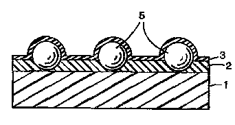
Fig. 3 is a scnemalic cross-sectior.al view of a ~
further preferred emoodlment of Ihe lmage-receiving _lm
of the present inventior,. The image-receiving film ~=
according to this embodiment has the same constructicn as
ir. Fig. 1, except t;hat the image-receiving layer 2
provided on the ~ransparent substrate l contains fine
particles 5 (silica part cles ir. thls case) and is
covered with the overcoat layer 3. The overcoat laye- 3
comprises a silicone oil adsorbent (compound having a
carboxyl group or compour.d having a hydroxyl group).
Flne particles include silica particles and fine
particles of various other inorganic and organic
materials are useful. Suitable examples of the fine
particles include those of silica, alumina, calcium
carbonate, diatomaceous earth, plymethacrylate and
polystyrene. The incorporation of these fine partic es
into the image-receiving layer are favorable from the
viewpoint of reducing the oil pooling phenomenon and more
smoothly carrying the film (i.e., improving the
feedability of the film) within copying machines.
When the silica particles are incorporated into the
image-receiving layer, they may be in the form of a
--11--
W096/02022 I~l/L~ . _ _
?il'.~ l; 9
primary particle or an aggregate of particles. The
particle diame~er of the silica particles or aggregate
may be prefera~ly in the range of from 1 to 100 um. When
it is less than 1 um, the effect of reduclng the oil
pooling phenomenon is poor and an improvement in
feedability is small. When it exceeds 100 um, the light
transmittance Is lowered, which results in an increase in
haze. The particle diameter is more preferably in tbe
range of from ~ to 50 um, most preferably in the range of
from 8 to 25 um.
Preferably, the silica particle contains the above-
described silicone oil adsorber.t (compound havir.g a
carboxyl group or compound having a hydroxyl group).
Wr.en the silicone cil adsorben~ compounds are
ir.corporated into the image~receiving film in this way,
the particles are protruded on the surface of image-
receiving film. The intended effect can be attained even
when the amount of the silicone oil adsorbent compour.d(s)
added is small, and the effect is maintained, so that
there is no fear of the light transmittance being
lowered.
Eurther, the silica particles may be incorporaled
ir..o the overcoat layer instead of or in addition tc ,he
image receiving layer. This is suitable from the
viewpoint of reducing the oil pooling phenomenon and
improving the feedability of the film, and when added to
the overcoat layer, the effec~ seen from the particles is
larger for the amount added.
According to a preferred embodiment of the present
invention, the antistatic effect of the film can be
enhanced by adding an antistatic agent to any layer
constituting the image-receiving film. Examples of
useful antistatic agents include quaïernary ammonium
salts and vario~s clay particles.
~ W096/02022
~ 2 ~3~ J 9
The addition of the antistatic agent reduces the
s~rface resistivity of the image-receiving film.
Therefore, the amount of the antistatic agent added -s
preferably determined by taking the surface resistiv--y
of the film into consideration. Although the surface
resistivity varies depending upon the specific copylr.
machine used, it is suitably in the range of from 1 x 10
tc 1 x 10li Q. When it is less than 1 x 10- Q, the
transfer of the toner is poor. On the other hand, w:-en
it exceeds 1 x 10'4 n, the film cannot be smoothly ca~ried
w:~hin copying machines. The surface resistivity is more
preferably ln the range of from 1 x 10' to 1 x 10i; n.
The image-receiving film of the present inventic.
may be prepared by various techniques depending upor. ilm
layer construction and other factors. In one examp;e of
a useful technique, an image-receiving layer is formei by
ccating directly on a substrate film, and drying. AC~er
t:~e resultant coating is dried, a solution of the
selected silicone oil adsorbent and an antistatic agent
d:ssolved in ethanol are coated. The coating operataon
may be carried out by coating methods commonly used ~.
t.e art, such as Mayer bar coating, a & M extrusion
c_ating, die coating, Narr coating, gravure coating a.ld
k:ss coating.
Mode of Operation
As described above, the effect of the present
invention relies largely on the function of the specf~ic
c~mpound having a carboxyl group or a hydroxyl group Ised
as a silicone oil adsorbent. This will now be descr bed
w:-ile taking 12-hydroxystearic acid as an example
particularly with reference to a schematic diagram s~own
i- Fig. 4.
12-Hydroxystearic acid is soluble in an oil at ~he
melting point or above. When the resultant solutior is
-13-
W096/02022
~. 2 1~32 1'9
allowed to stand, the temperature decreases with time,wr.ich causes molecules to be arranged thrQugh a hydr_~en
bond in a three-dimensional manner, 50 that a network
s~ructure 6 similar to that of poiymeric c-ompounds s
fcrmed as a whole. It is considered that a silicone -il
7 ls incorporated in the network structure 6 and gels.
As a result, the migration of silicone oil is prever~-d,
which contributes to a reduction in surface oiliness -f
the film.
EXAMPLES
The present inven~lon will now be described in -~re
de~ail with reference ~o the fcllowing examples.
Example 1
A transparenr polyester resLn was coated on a ;~_ um
thick transparent polves~er film ~a substrate~ at a
c_verage of 2.5 g/m ~o form an image-receiving layer.
T:een, a solution of ~q 5 g of 12-hydroxyslearic acic ,nd
12.6 g of an artistatic agent comprising a quaternar:
a.monium salt dissolved in 3043 g of ethanol was coa-ed
t-ereon by extrusion coating to form an overcoat laye-.
I:-e coverage of the overcoat layer on a dry basis was 0.5
g/m-.
An image was formed on the resultant image-form:-g
f:lm by means of a color copylng machine The image~
.ilm was used as an OHP film to evaluate the propert-=s.
Laser Copia CLC200 ~a reqistered trade mark) (a color
laser copying machine manufactured by Canon Sales Co.,
_-c.) was used as the coLor copying machine.
Oil pooling test
The film under test was lnserted into Flip-FraFe~: (a
f:lm holder manufactured by 3M, U.S.A ), and observa-ion
was made by visual inspection for pooling caused by a
-14-
_ W096/02022
932 ~ 9
silicone oil. The results were evaluated based on the
following three grades.
[Excellent] No pooling observed
[Good] Substantially no pooling observed
[Failure] Pooling clearly observed
Touch test (evaluation on oiliness)
The film under test was touched with a finger, a-.d ~:~
the results were evaluated as follows. :T
[Excellent] No oiliness observed
[Good] Subs~antially no oiliness observei
[FailureJ Oiliness clearly observed
Haze test
In order to evalua~e the occurrence of haze in -:e
film under test, the haze value was measured with a ;saze
meter manufactured by '3~K Gardner (available under the
designation XL-211" and the results were evaluated as
follows.
[Excellent] Less than 8
[Good] 8# to less than 12
[Failure] Not less than 12~
Image qualitv test
The film under test was inserted into Flip-Frame-:,
and an image was pro~ecled by means of OHP "M2180"
manufactured by 3M, U.S.A. The pro~ec~ed image (tes
pattern) was observed by visual inspection, and the
reproduction of the imaqe was evaluated as follows.
[Excellent] Complete reproduction
[Good] Satisfactory reproduction
[Failure] Unsatisfactory reproduction
No oil pooling was observed at all. In this
connection, it is noteworthy that neither the background
WO 96101022 ' 1 ~ 1~91 3 2 1 9
nor image had oil pooling. Further, no oiliness was elt
when the surface of the film was touched with a finge~.
The haze value was very low, and the image reproduct-~n
was excellent. ~The results obtained in this example
together with the results obtained in the other examp es
are given in the following Table 1.
Example 2
The procedure o~ Example l was repeated, except _hat
an image-receiving layer was formed by coating a solu-ion
of 300 g of a ~olyester resin (PS-2 manufactured by .~ao
Corp.) and 6.0 g of a polyester resin (VITEL 2200
manufactured by Goodyear Tire & Rubber Co.) as ar.
adhesive composition for improving the adhesion to a
toner, dissolved in 1347 g of toluene and 1347 g of
methyl ethyl ~etone. The coverage of the image-rece:ving
layer was 2.5 q/m . Then, a solution of 68.8 g of 12-
hydroxysteariczacid and 16.1 g of an antistatic agen~
comprising a quaternary ammonium salt and 2.29 g of
Silica MC-A manufactured by Nai-Gai Ta~c Co., Ltd.
dissolved in 2207 g of ethanol was coated on the imaae-
receiving layer to form an overcoat layer. The coverage
of the overcoat layer was 0.5 gim on a dry basis. .-._
with Example 1, this example providea good results. ~he
results are given in the following Table 1.
Examples 3 to 7
The procedure of Example 1 was repeatedl except ~hat
instead of 12-hydroxystearic acid, the following
compounds were used in the same amounts as 12-hydroxy
stearic acid.
Example 3 ~ dibenzyl-dienesorbitol
Example 4: ammonium stearate
-16-
_ W096/02022 P~~ .;A
' ~ '9321 9
Example 5: zinc stearate
Example 6: stearic acid
Example 7: 1,10-decanediol
As with Examples 1 and 2, Examples 3 to 7 provi~ed
gocd results. The results are shown in Table l.
.,
Examples 8 to 10 _~
The procedure of Example 1 was repeated, except ~hat
the antistatic agent used was a commercially availak_e :
ar._istatic agent as noted below used in the same amo_ ;s
as the antistatic agent used in Example 1.
~xample 8: Electrostopper QE (a cationic antis'_-ic
agent manufactured by Kao Corp.)
Example 9: Chemistat 3033 (an anlonic antistati_
agent manufactured by sanyo Kasei Kc-yo
K.K.)
~xample 10: Adekamine (a cationic antistatic age~-
manufactured by Asahi Denka Kogyo L-~ )
As with Examples l to 7, Examples 8 to 10 provided
good results, and no color dropout occurred. The re~_lts
a-e shown in Table 1.
Examples 11 and 12
The procedure of Example l was repeated, excepr -hat
t:e coverage of the overcoat layer was changed as
fc:lows.
Example 11: 0.1 g/m~
Example 12: l g/m~
As with the above examples, Examples ll and 12
provided good results. Thé results are shown in Tak:e 1.
Example 13
A solution of 0.50 g of 12-hydroxystearic acid, ~.50 --
g of a polyester resin (PS-1 manufactured by Kao Cor-.),
0.01 g of a polyester resin (VITEL 1200 manufactured by
WO 96/02022 P~.J/L~ '~ _
2~ ~32 i ~ --
Goodyear Tire & Rubber Co.), 0.015 g of an antistatic
agent derived from a quaternary ammonium salt dissolved
in 2.16 g of toluene and 2.16 g of methyl ethyl ketone
was coated using a #12 Mayer bar on a 125 um thick
transparent polyethylene terephthalate film (a substrate)
at a coverage of 2.5 g/m' to form an image-receiving
layer.
The film as imagea in the same manner as descrired
in Example 1, and the imaged film was tested for
evaluation of properties. The results are shown in able
1.
Table l
Test for image-rece~i~g films
Items for test
Oil Image
Pooling Touch Quality
Ex. No. Test Test Ha7e Test Test
1 Excellent Excellent Excellent Excellen~
2 Excellent E~cellent Excellen~ Excellen
3 Excellent Excellent ~Pll~nt Excellen
4 Excellent Excellent Excellent Exceller
Excellent Excellent Excellen~ Exceller.r
6 Excellent Excellent Excellent Exceller.~
7 Excellent Excellent Excellent Excellen~
8 Excellent Excellent Excellent Excellen
9 Excellent Excellent Excellent Exceller_
Exc~llent Excellert Excellent Exceller.r
11 GDDd Good Excellent Excellent
12 Excellent Excellent Good Good
13 Good Good Good Good
-18-
W096/02022 '~ 2 ~ 9 P~ .5
Comparative Examples 1 and 2
The procedure of Example 1 was repeated, except
that, for comparison, 12-hydroxystearic acid was not
added to the overcoat layer and the coverage of the
overcoat layer was changed as follows.
Comparative Example 1: 0.5 g/m~
Comparative Example 2: 0.1 g/m~
The results are given in the following Table 2.
Comparative Example 3
In the present comparative example, the procedure
described in Japanese Unexamined Patent Publication
(Kokai) No. 5-173351 was repeated.
50 parts by weight of xylene, 10 parts by weigh~ of
methyl methacrylate, 11 parts by weight of n-butyl
methacrylate, 10 parts by weight of 2-hydroxyethyl
methacrylate, 18 parts by weight of styrene, 0.5 parts by
weight of acrylic acid and 0.5 parts by weight of
azobisisobutyronitrile were mixed together in a flask,
and the mixture was stirred ae 80~C for 2 hr to carry out
a polymerization reaction. As a result, a
polymethacrylic ester~styrene copolymer having a hydr~xyl
number of 80 was obtained. A solution comprising 20
parts by weight of the copolymer, 20 parts by weight -r a
polymer of a quaternary ammonium salt (Elecond PQ-50~
manufactured by Soken Chemical Engineering Co., Ltd.,, 30
parts by weight of toluene and 30 parts by weight of
methyl isobutyl ketone was prepared and coated on a _
mil-thick polyethylene terephthalate film at a coverage
of 5 g/m- on a dry basis. As is apparent from Table 2,
the image-receiving film thus obtained was unsatisfactory
in silicone oil adsorption and other properties.
--19--
W096/02022 ~ ? ~ 2 l 9
[Table 2]
Characte~istic test for image-receiving films
Items for test
Oil Image
Pooling Qua::ty
Ex. No. Test Touch Test Haze Test Test
l Failure Failure Excellen~ Exce; ent
2 Failure Failure Excellent Exce lent
3 Failure Failure Failure Failure
According to the present invention, in image-
receiving films, for example, for OHP, the occurrence of
an oil pooling phenomenon can be reduced, and a sill~one
oil, which has been once held on an image-receivirlg
layer, can be kept on the image-receiving layer.
Further, it is also possible to reduce the transfer ~_ an
silicone oil upon touch on the film with a finger.
Moreover, according to the present inventior., it is also
possible to enhance the feedability of the }:lm wi~h-n a
copying machine. In addition, in the present invenr:on,
the film constructio~ is simple, and all the materia's
used are easily available and inexpensive, which
contributes to a lowering in product cost.
BRIEF DESCRIPTION OF THE DRAWINGS
Fig. 1
Fig. 1 is ~a schematic cross~sectional view of a
preferred embodiment of the image-receiving film for
electrography according to the present invention
Fig. 2 =
Fig. 2 is a schemaric cross-sectional view of
another preferred embodiment of the image-receiving ilm
for electrography according to the present invention.
-20-
~ W096l02U22 ~l 9
c~ 3 2 1 9
Fig. 3
Fig. 3 is a schematic cross-sectional view of a
fu~ther preferred embodiment of the image-receiving ~:lm
~ fo- electrography according to the present invention.
Fig. 4
Fig. 4 is a schematic diagram showing typical
gelation of a silicone oil according to the present
invention.
Fig. S
Fig. S is a schematic cross-sectional view show:r.g
ar. embodiment of the conventional image-receiving f~
fcr electrography.
Description of Reference Numerals
1 substrate
2 image-receiving layer
3 overcoat layer
4 image-receiving layer
S adsorptive particle
6 networ~. structure of 12-hydroxystearic aci~
7 silicone oil
, !: ,, '
-21-