Note: Descriptions are shown in the official language in which they were submitted.
219~ai~
WO 95135129 PCT/US95105671
CATHETER APPARATUS
BACKGROUND OF THE INVENTION
1. Field of the Invention
The invention relates to catheters for intravenous applications.
2. Description of the Related Art
Each year, the number of individuals who are infected with Human
Immuno-deficiency Virus (NIV), Hepatitis B (HPV), and other dangerous diseases
is increasing. Currently, the Center for Disease Control (CDC) estimates that
from
1.5 - 2 million people in the United States are infected with HIV. Many of
these
io HIV cases are undiagnosed, which makes anyone who comes in contact with the
infected person's body fluids vulnerable to HIV infection as well. Nurses and
doctors are particularly vulnerable to HIV infection because their work
involves
working closely with the body fluids of their patients.
One significant source of HIV exposures for health care workers is
accidental needfesticks. The number of accidental needlesticks is estimated to
be
more than one million per year.
Of these, roughly 2% are contaminated by HIV. To make matters worse,
about 50°l0 of HIV needlesticks go unreported. The significance of this
problem is
borne out by the fact that 80°I° of HIV exposures to health care
workers are
2o caused by needlesticks. Of these needlesticks, one in 200 results in an HIV
infection.
The CDC also estimates that 12,000 health care workers in the United States
will
become infected with HPV each year. Over 80% of those HPV infections acquired
occupationally by health care workers will be as a result of needlesticks or
other
1 ~ .~ :°':. i' (~
WO 95J35129 PCTII35951t15671
2
sharp instruments. Of those infected, over 200 wilt die.
Clearly, there is a vital need for reducing the occurrence of this type of
accident.
Studies reveal that more that 75°~0 of needlesticks occur after use
of the
needle, in preparation far, or during disposal. Yet despite special
precautions
such as the use of containers for needles to be discarded and educational
programs for health workers, the incidence of needlesticks has not been
significantly reduced. lNany experts predict that this situation will not
change until
needles and catheters of safer design are introduced.
Typical catheter designs for intravenous applications require that an
to introducing needle be used to create an opening in a vein into which the
catheter
can be inserted. The disadvantage of this approach is that body fluids can
discharge from the opening while the needle is being withdrawn and the
catheter
inserted, thus risking exposure to the health care worker. Furthermore,
neither the
needle or catheter contains a means of protecting the worker from a
needlestick.
i5 Attempts have been made to provide a needle which can be withdrawn into
a protective shield. A typical example of this type of apparatus is the
PROTECTIVT"' catheter marketed by Gritikon, lnc. This device has an
introducing
needle which includes a protective guard for preventing contact with the
needle
during and after use. A catheter is attached to the needle, the needle is used
to
2o provide an introducing opening within the vein of a patient, and the
catheter is
inserted into this opening by sliding it off the needle as the needle is
withdrawn
into the protective guard. The needle is then removed from the catheter and
discarded.
However to complete the procedure, such devices, including the
PROTEGTIVT"°
~l9~ui'6
W 0 95/35129 PCTlUS95/05671
3
design, requires that the user then attach the catheter to the intravenous
tubing.
During this attachment, the user is vulnerable to exposure to the patient's
blood.
In the case of hemodialysis, this potential for the exposure discourages the
use of catheters of this type. Instead, needles that are attached directly to
intravenous tubing are preferably used. For hemodialysis patients, doctors
must
often perform surgery upon the patient to create a fistula. A fistula is a
large,
highly accessible vein, built from connecting one of the patient's veins with
an
artery, and designed to better accommodate numerous intravenous injections or
withdrawals. Nevertheless, the introduction of the needle into the dialysis
fistula
~.o risks causing significant local trauma of several varieties. Whenever a
needle is
inserted in the fistula, the potential for trauma to the fistula tissue
exists. Further,
when a needle is left in place during the hemodialysis procedure, it presents
potential trauma since it may be moved to the point that it impacts or even
penetrates the opposite wall of the fistula, thus leading to infiltration and
bleeding.
is Furthermore, the removal of the dialysis needle is accompanied by applying
pressure to the exit site, which usually traumatizes the inner surtace of the
fistula,
resulting in a tendency for scarring of the fistula.
The repetitive traumatization of dialysis fistulas often leads to failure of
the
fistula, which is the primary cause of hospitalization for patients with End
Stage
2o Renal Disease. The use of catheters for hemodialysis offers significant
advantage
over metal needles. Since the catheter can be manufactured from a flexible,
non-
traumatizing material such as Teflon, the only trauma to the fistula is
limited to the
initial insertion of the introduction needle.
A device which allows placement of an intravenous tubing-connected
Wp 95135129 E- ~ r~ ~ ~ ~ C~ PCTJU595/115671
4
catheter inside the vein without the need to remove the introducing needle,
while
allowing secure enclosure of the needle so as to prevent subsequent
n2edlesticks
is not disclosed in the prior art.
SUMMARY OF THE INVENTION
s It is the object of the invention to provide a catheter apparatus which can
place a catheter inside the patient' vein or fistula without requiring the
removal of
the introducing needle.
It still another the object of the invention to provide a catheter apparatus
which completely encloses the introducing needle after use so that it cannot
to produce a needlestick.
It still another the object of the invention to provide a catheter apparatus
which secures the introducing needle with the apparatus after use.
It still another the object of the invention to provide a catheter apparatus
which is substantially leak-free.
15 It still another the object of the invention to provide a catheter
apparatus
which can be connected to intravenous tubing prior to insert the catheter in
the
patient.
It still another the object of the invention to provide a catheter apparatus
that enables the viewing of the flashback of blood once the introducing needle
has
zo been introduced into the vein.
The invention is an apparatus for intravenous medical procedures. A
housing having a barrel with an interior cross-section is provided. The
housing
has a tip at one end and a plunger opening at the other end. Tip of said
housing
has a tip bore with a diameter. The tip bore extends into the barcel of said
1 ~:~iJi'6
WO 95J35129 PCTlUS95105671
S
housing. A plunger having a needle opening, and an intravenous tubing line
opening is provided. Said plunger has an exterior cross-section corresponding
to
the interior cross-section of the barrel of said housing. An introducing
needle
having a point and a gauge size corresponding to the diameter of the tip bore
is
s provided. Said needle is rigidly connected to the needle opening of said
plunger,
such that when said plunger is fully inserted into the barrel of said housing,
said
needle extends through said tip bore. Locking means for holding said plunger
in a
fixed retracted position relative to said housing is provided. When said
plunger is
in the fixed retracted position, the paint of said introducing needle is held
within
io the tip bore of said housing. A flexible catheter, having a venous end and
an
attachment end is provided. The attachment end of said catheter is permanently
attached to the tip of said housing. Said catheter has a gauge size
corresponding
to the gauge of said needle. When said plunger is fully inserted into said
housing,
said introducing needle extends through said flexible catheter with the point
of said
is needle extending beyond the venous end of said catheter. When said plunger
is
in the fixed retracted position, a continuous path for conducting the flow of
fluids is
provided extending from the venous end of the catheter through the catheter,
through a portion of the tip, through said introducing needle, through the
plunger
and exiting the intravenous tubing line opening of said plunger.
2o BRIEF DESCRIPTION OF THE DRAWINGS
Figure 1 is an isometric view of the catheter apparatus in accordance with
the invention.
Figure 2 and Figure 3 are longitudinal cut-away views of the catheter
device, showing the introducing needle before use and after use, respectively.
R'O 95135129 ~ ~ ~ ~ ~~ ~ ~ PCTIUS95!(15671
6
Figure 4 and Figure 5 are longitudinal cut-away views of an alternative
embodiment of the invention.
DETAILED DESCRIPTION OF THE INVENTION
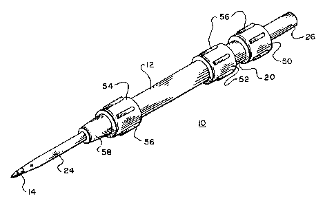
Figure 1 is an isometric view of catheter apparatus 10. The material
selected for the construction of the invention are preferably plastics of the
type
that is typically used for constructing such medical devices. The external
shape of
the invention, including housing 12, is preferably cylindrical but other cross-
sectional shapes would be acceptable.
Housing 12 is externally made up of tip 58, insertion collar 54, barrel 59,
to and housing retraction collar 52. A plurality of grips 56 are
longitudinally place
along collars 54 and 52. The diameter of housing 12 and ifs associated
component parts are not critical and can be sized similar to present catheter
devices. In this manner, medical personnel will be instantly comfortable with
the
use of the invention without needing to be accustomed to a differently sized
i5 apparatus.
Housing 12 can be manufactured in a number of ways, however, the most
practical from a cost and quality perspective is to inject mold the unit. With
the
exception of tip 58, which is preferably color caded to indicate gauge size,
housing
12 should be substantially translucent to permit medical personnel to detect
blood
2o flashback.
Fitted within housing 12 at tip 58 is catheter 24. Catheter 24 is preferably
flexible tubing of a type that is typical for use in catheters such as Teflon.
Any
materials that have been approved for catheter use are acceptable. Catheter 24
is
attached within tip 58 using techniques well known in fhe art such as electro-
~193oi'6
WO 98133129 PCTlCTS951(15671
7
welding.
Slidably mounted within housing 12 is plunger 20. Attached to plunger 20
is needle 14. Catheter 24 and needle 14 are sized so that needle 14 can be
used
as an introduction needle for catheter 24. Attached to plunger 20 is plunger
collar
50 which like its housing counterparts features grips 56. Attachment end 26 is
provided at the end of plunger 20. Attachment end 26 is shaped and
dimensioned so that a standard IV set (not shown) can be attached.
Figure 2 is a longitudinal cut-away side view of catheter apparatus 10,
showing needle 14 before use. Within tip 58 is bore 61 which is sized so that
needle 14 can slide through yet be sufficiently tight to keep needle 14
rigidly
aligned within housing 12 and prevent fluid from leaking between needle 14 and
tip 58. As noted above, needle 14 is firmly attached to plunger 20. Opening 62
in
barrel 53 is provided within plunger which serves to direct fluid flow from
needle
14 to attachment end 26.
is Locking fingers 22 are attached to the inside wall 63 of barrel 53. The
number of locking fingers 22 is not critical but at least two is preferable so
that
plunger 20 will be symmetrically held within housing 12. Locking fingers 22
are
resilient metal or plastic projections which can be easily flexed by plunger
head 28
as plunger 20 is retracted from housing 12. Head 28 is preferably chamfered at
2o corner 64 so that fingers 22 can easily move around head and be locked in
position on surface 65 of head 28, once plunger 20 is fully retracted as shown
in
Fig. 3.
To use catheter apparatus 10, an IV set is attached to attachment end 26.
An operator grasps housing 12 via insertion collar 54 and inserts needle 14
and
~~~~~;~~6
W0 95135129 PCTJU$95/05671
8
the attached catheter 24 into a vein or fistula of the patient. The operator
then
retracts plunger 20 by grasping housing retraction collar 52 with one hand and
plunger collar 50 with the other hand. Simultaneously, the retraction of
plunger 20
retracts needle 14 through bore 61. Recall that bare 61 is dimensioned so that
filuid cannot leak past needle 14. As plunger 20 and attached plunger head 28
are
further retracted, locking fingers 22 are pried apart, sliding over chamfer
64, until
plunger head 28 moves past fingers 22. At that point, locking fingers 22 snap
back to their original positions locking head 28 in position via surface 65,
thus
preventing plunger head 28 being pushed in the reverse direction. Plunger stop
la 18 prevents plunger head 28 from being retracted completely out of housing
12.
At this point, shown in cross-section in Figure 3, needle 14 is completely
enclosed
and securely locked within housing 12 and bore 61. Catheter 24 can be advanced
into vein or fistula by advancing collar 54. Also, since an IV tubing line is
connected to attachment end 26, the medical procedure such as hemodialysis can
is be immediately initiated without having to break the line with the
attendant risk of
contamination. Once the procedure is completed, catheter apparatus 10 can be
removed from the patients vein and discarded, knowing that tip 66 of needle 14
is
still completely enclosed and securely locked within housing 12 and bore 61.
Figure 4 is a longitudinal cut-away side view of an alternative embodiment
2a of catheter apparatus 10, showing needle 14 before use. Housing 12 contains
substantially hollow plunger 20, to which needle 14 is attached. In this
embodiment, plunger head 28 is modified to flared end 72. Since head 28 is
preferably a compliant material such as rubber, end 72 will be compressed as
plunger 20 is withdrawn, urged by taper 74 of barrel 53. Once plunger 20 is in
a
?~9a~i
WO 95135129 PCT/ITS95105671
9
fully retracted state as shown in Fig. 5, plunger 20 is locked by flared end
72
being held within notch 73, formed by incline 75 of stop 18 and surface 77 of
barrel 53. As in the preferred embodiment, the operator is prevented from a
needlestick since tip 66 of needle 14 is completely enclosed within tip 58.
s While there have been described what are at present considered to be the
preferred embodiments of this invention, it will be obvious to those skilled
in the
art that various changes and modifications may be made therein without
departing
from the invention and it is, therefore, aimed to cover all such changes and
modifications as fall within the true spirit and scope of the invention.