Note: Descriptions are shown in the official language in which they were submitted.
~~.93~~
TITLE OF THE INVENTION
SEPARATE OILING TYPE TWO CYCLE ENGINE
BACKGROUND OF THE INVENTION
1. Field of the Invention
The present invention relates to a separate oiling
type two cycle engine and more particularly to a separate
oiling apparatus for a two cycle engine having a float-less
type carburetor.
2. Prior Art
Generally, separate oiling type two cycle engines
for marine use or those engines used in coast areas need
countermeasures to prevent salt damage. For example, Japanese
Unexamined Patent Application laid open No. Toku-Kai-Hei 4-
191409 discloses a technology to prevent carburetor compo-
vents such as a throttle valve or a choke valve from being
stained, rusted or corroded by salt contained in the intake
air.
According to the technology disclosed in the prior
art, an oil supply hole is provided on the upstream side of
the bearing section of the choke valve to prevent the valve
rotating shaft of butterfly valves from being stuck due to
salt damage.
However, a defect of this technology is an insuf-
ficient supply of oil to inner components of the carburetor,
such as a needle valve, metering needles, metering jets, a
1
~~.q~43
metering chamber, and miscellaneous fuel passages, leading
to salt damages on these components. Especially, in case
where salt water is contained in fuel, it comes into the
carburetor together with fuel and may cause corrosion or rust
in fuel passages, metering jets. °,rother defect is oil stuck
to the inner wall of the intake manifold due to an inadequate
mixing with fuel.
To solve these problems, Japanese Unexamined
Patent Application laid open No. Toku-Kai-Hei 7-119553 dis-
closes a diaphragm type carburetor in which a lubricating oil
supply hole is provided downstream of and adjacent to the
check valve for supplying fuel into the metering chamber,
whereby lubrication of the metering chamber and mixing of
fuel with lubricating oil being improved.
However, the above technique also has a disadvan-
tage that the mixing of fuel with oil in the metering cham-
ber become insufficient particularly when the engine is in a
wide open throttle condition or at a high speed condition.
SUMMARY OF THE INVENTION
Accordingly, the present invention is intended to
minimize the abovementioned shortcomings of previous arts and
it is an object of the present invention to provide a sepa-
rate oiling type two cycle engine capable of lubricating
inner components of a carburetor such as fuel passages,
miscellaneous metering jets, needle valves and nozzles as
2
~1~~~~
well as a choke valve and a throttle valve in order to pre-
vent these carburetor components from being damaged by salt
water contained in fuel. Means to achieve the object com-
prise:
a needle valve for regulating the amount of fuel;
a fuel reservoir for reserving fuel;
a fuel supply port provided at the fuel reservoir
for supplying fuel into the fuel reservoir;
a fuel passage for connecting the fuel reservoir
with the needle valve;
an oil discharge port provided adjacent to the
inlet of said needle valve for discharging lubricating oil
therethrough so as to mix lubricating oil with fuel; and
a fuel return port provided at the higher position
than the fuel supply port for returning fuel to a fuel tank.
BRIEF DESCRIPTION OF THE DRAWINGS
Fig. 1 is a schematic diagram showing a construc-
tion and an operation of a carburetor according to an embodi-
ment of the present invention;
Fig. 2 is a top view of an engine according to the
present invention;
Fig. 3 is a side view of an engine according to
the present invention; and
Fig. 4 is an enlarged sectional view of a portion
enclosed by a circle A.
3
DETAILED DESCRIPTION OF PREFERRED EMBODIMENTS
Referring now to Fig. 2 and Fig. 3. numeral 1
denotes a separate oiling type two cycle engine and in this
embodiment it shows a three-cylinder engine for a personal
water craft use. A spark plug 4 is disposed in a cylinder
head 3 of a cylinder 2. Further, a carburetor 5 is incorpo-
rated on the intake side of each cylinder 3 and an exhaust
port (not shown) for each cylinder 3 is formed on the oppo-
site side of the carburetor 5.
Lubricating oil is supplied from an oil pump 6 to
each of these carburetors 5 through a pipe 7. Fuel is fed
from a fuel tank Cnot shown) to a fuel supply hole 8 of the
carburetor 5 and returned from a fuel return hole 9 to the
fuel tank.
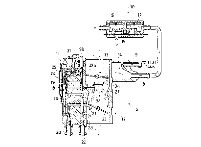
Further, as illustrated in Fig. 1. the carburetor
is a diaphragm type float-less carburetor which comprises a
metering chamber 11 for regulating and reserving fuel sup-
plied from a fuel pump 10. a mixing chamber 12 for forming
air-fuel mixture and feeding it to the engine and a fuel
reservoir 14 for reserving fuel. The above metering chamber
serves as regulating fuel so as to forming a proper air-fuel
ratio of mixture gas. Further, there is provided with a fuel
passage 13 having a specified length between the metering
chamber 11 and the fuel reservoir 14.
The fuel pump 10 feeds fuel from the fuel supply
4
hole 8 to the fuel reservoir 14 by the operation of a spring
diaphragm 15. a suction diaphragm 16 and a discharge dia-
phragm 17 respectively moving up and down according to the
changing pressure of the crank case chamber.
Further, in the carburetor 5 there are provided a
metering diaphragm 18 operated by the pressure difference
between intake negative pressure and atmospheric pressure, a
diaphragm chamber 19. a fuel passage connecting the diaphragm
chamber 19 with a bypass hole 21 through a slow screw 20. a
fuel passage connecting the diaphragm chamber 19 with a pilot
outlet 23 through a pilot screw 22 and a fuel passage con-
necting the diaphragm chamber 19 with a main nozzle 28 of an
inner venturi 27 in the mixing chamber 12 through a check
valve 24. a main jet 25 and a metering needle 26. The slow
screw 20. the pilot screw 22 and the metering needle 26 have
been adjusted beforehand respectively so as to obtain a
proper amount of fuel.
Further, in the diaphragm chamber 19 of the meter-
ing chamber 11. there is provided with a metering arm 29
pushed and operated by the movement of the metering diaphragm
18 so as to open and close a needle valve 30 disposed in the
fuel passage 13.
Further, the fuel supply hole 8 is provided in the
fuel reservoir 14 so as to supply fuel to the metering cham-
ber 11 through the fuel passage 13 and the needle valve 30
and a fuel return port 9 is provided on the upper side of the
219393
fuel supply hole 8 so as to bring back return fuel to the
fuel tank therethrough.
Referring to Fig. 4. there is provided with an oil
discharge port 32a for discharging lubricating oil supplied
from the oil pump 6 in the fuel passage 13 immediately adja-
cent to the entrance of the venturi 31. Further, upstream of
the oil discharge port 32a there is provided with a check
valve 32 for preventing a reverse flow of oil.
On the other hand, a throttle valve 33 is disposed
downstream of the inner venturi 27 of the mixing chamber 12
and a choke valve 34 is disposed upstream thereof. Downstream
of the throttle valve 33 an intake pipe 35, a crank case 36
and a cylinder 2 are arranged in this order.
Next, an operation of the carburetor constituted
above will be described.
First, when the engine 1 starts cranking, the
crank case pressure is changed by the reciprocating motion of
the piston anc' the spring diaphragm 15 of the fuel pump 10
which is connected with the crank case is operated as shown
by an arrow mark in Fig. 1. The fuel pump 10 may be used as
one for each carburetor or one for all.
The operation of the spring diaphragm 15 induces
an operation of the suction diaphragm 16 and the discharge
diaphragm 17 and as a result the fuel inside of the fuel pump
is sent to the fuel reservoir 14 through the fuel supply
hole 8.
6
On the other hand, the metering diaphragm 18 of
the metering chamber 11 is operated by the pressure differ-
ence between atmospheric pressure and intake negative pres-
sure to send fuel mixed with lubricating oil to the bypass
hole 21 through the slow screw 20, the pilot outlet 23
through the pilot screw 22. and to the main nozzle 28 of the
inner venturi 27 through the check valve 24. the main jet 25
and the metering needle 26. Further, the metering diaphragm
18 pushes the metering arm 29 so as to open the needle valve
30.
When the needle valve opens, the fuel in the fuel
reservoir 14 flows into the metering chamber 11 through the
venturi 31. Then, lubricating oil supplied from the oil pump
6 is discharged from the oil discharge port 32a and mixed
with fuel adequately when fuel passes through the venturi 31
and the needle valve 30 with high speed. Further, in the
metering chamber 11 the mixing of fuel and oil is enhanced by
the vibrating motion of the metering diaphragm 18. When the
engine comes into the high speed condition, the vibrating
motion of the metering diaphragm 18 becomes small. However,
on the other hand, the amount of fuel consumed by the engine
increases and the flow speed of fuel becomes so high as to
encourage mixing of fuel and oil when they pass through the
venturi 31 and the needle valve 30. In this embodiment. the
oil discharge port 32a is provided immediately before the
venturi 31 but alternatively it may be provided at the other
7
~193~3
portion adjacent to the inlet of the needle valve 30.
The oil mixed with fuel lubricates the slow screw
20, the pilot screw 22, the check valve 24, the metering
needle 26, and miscellaneous fuel passages in the carburetor.
When fuel is ejected from the bypass hole 21, the
pilot outlet 23 and the main nozzle 28, it is atomized in the
mixing chamber 12 and sucked into the cylinder 2. When fuel
is atomized, a part of of l contained in fuel lubricates the
choke valve 34 and the throttle v;.lve 33 and the rest of oil
is sucked into the cylinder 2 to lubricate the piston. The
reason why the choke valve 34 located upstream of the main
nozzle 28 is lubricated is that the reverse flow of mixture
gas occurs due to the blow-back phenomenon of engine.
The fuel not sent to the metering chamber 11 is
returned to the fuel tank through the fuel return port 9
which is located at the high position of the fuel reservoir
14.
Thus, according to the embodiment of the present
invention, since lubricating oil is discharged from the oil
discharge port which is located ~:nmediately before the ven-
turi and js mixed with fuel white fuel and oil pass through
the venturi and the needle valve with high speed, and further
mixing of fuel and oil is enhanced in the diaphragm chamber
by the vibrating operation of the metering diaphragm, miscel-
laneous fuel passages, metering needles, metering jets and
other components in the carburetor can be prevented from
8
~193a3
being corroded, rusted or clogged by the oil contamination.
Further, since the mixing of of l and fuel is conducted more
completely as described above, excessive sticking of oil to
the inner wall of the intake pipe can be prevented. Further,
oil consumption can be regulated properly and smoke emissions
particular to two cycle engines can be reduced. Further,
since the choke valve and the throttle valve is lubricated
enough by lubricating oil, these moving components can be
prevented from being stuck due to salt damage.
Further, since the fuel reservoir has an enough
volume to reserve fuel and the fuel passage connecting the
fuel reservoir with the needle valve has a specified length
so as to restrain the back-flow of lubricating oil, and since
lubricating oil has a larger specific gravity than fuel and
the fuel return port is located ~:f the high position of the
fuel reservoir, fuel mixed with oil can be prevented from
being returned to the fuel tank.
While the presently preferred embodiment of the
present invention has been shown and described, it is to be
understood that this disclosure is for the purpose of illus-
tration and that various changes and modifications may be
made without departing from the scope of the invention as set
forth in the appended claims.
9