Language selection

Search

Patent 2194077 Summary

Third-party information liability

Some of the information on this Web page has been provided by external sources. The Government of Canada is not responsible for the accuracy, reliability or currency of the information supplied by external sources. Users wishing to rely upon this information should consult directly with the source of the information. Content provided by external sources is not subject to official languages, privacy and accessibility requirements.

Claims and Abstract availability

Any discrepancies in the text and image of the Claims and Abstract are due to differing posting times. Text of the Claims and Abstract are posted:

  • At the time the application is open to public inspection;
  • At the time of issue of the patent (grant).
(12) Patent: (11) CA 2194077
(54) English Title: DUAL-MODE CAVITY FILTER
(54) French Title: FILTRE A CAVITE BIMODAL
Status: Term Expired - Post Grant Beyond Limit
Bibliographic Data
(51) International Patent Classification (IPC):
  • H01P 01/207 (2006.01)
  • H01P 01/208 (2006.01)
(72) Inventors :
  • CACERES ARMENDARIZ, JOSE LUIS (Spain)
(73) Owners :
  • ALCATEL
(71) Applicants :
  • ALCATEL (France)
(74) Agent: ROBIC AGENCE PI S.E.C./ROBIC IP AGENCY LP
(74) Associate agent:
(45) Issued: 2004-11-02
(22) Filed Date: 1996-12-27
(41) Open to Public Inspection: 1997-06-29
Examination requested: 2001-10-25
Availability of licence: N/A
Dedicated to the Public: N/A
(25) Language of filing: English

Patent Cooperation Treaty (PCT): No

(30) Application Priority Data:
Application No. Country/Territory Date
P9502560 (Spain) 1995-12-29

Abstracts

English Abstract

Comprising one or more resonant cavities in which are produced two resonant modes at two different frequencies f1 and f2, both modes having essentially the same field distributions but rotated 90 ° with respect to each other. Each cavity comprises a tuning element (TS a) for tuning the resonant frequency f1 of the first mode along a first axis, a tuning element (TS b) for tuning the resonant frequency f2 of the second mode along a second axis perpendicular to the first, input coupling means (IC) and output coupling means (OC) for injecting into and extracting from the cavity, respectively, a radiofrequency signal along axes not parallel to those of resonance. Filter tuning is done by using only two tuning elements, which means that the filter cost is lower and the tuning time is reduced.


French Abstract

Comprenant une ou plusieurs cavités résonnantes dans lesquelles sont produites deux modes de résonance à deux fréquences différentes F1 et F2, les deux modes ayant essentiellement les mêmes distributions de champ, mais avec une rotation de 90 degrés l'un par rapport à l'autre. Chaque cavité comporte un élément d'accord (TS a) pour accorder la fréquence de résonance f1 du premier mode suivant un premier axe, un élément d'accord (TS b) pour l'accord de la fréquence de résonance f2 du second mode suivant un second axe perpendiculaire au premier, un moyen de couplage d'entrée (IC) et un moyen de couplage de sortie (OC) pour injecter dans, et extraire de la cavité, respectivement, un signal radiofréquence suivant des axes non parallèles à ceux de la résonance. L'accord de filtre se fait en utilisant seulement deux éléments d'accord, ce qui signifie que le coût du filtre est plus faible et le temps d'accord est réduit.

Claims

Note: Claims are shown in the official language in which they were submitted.

-6-
CLAIMS
1: Dual-mode cavity filter comprising one or
more dual-mode resonant cavities in which in each cavity
first and second resonant modes are produced at two
different frequencies f1 and f2, both modes having
essentially the same field distributions but rotated 90°
with respect to each other, characterised in that each
cavity comprises:
- first tuning elements (TS a) to tune resonant
frequency f1 of the first resonant mode along a first axis,
- second tuning elements (TS b) to tune
resonant frequency f2 of the second resonant mode along a
second axis perpendicular to the first,
- input coupling means (TC) to inject a
radiofrequency signal into the cavity in accordance with
field polarization along axes not parallel to those or
resonance, and
- output coupling means (OC) to extract the
applied signal from the cavity in accordance with field
polarizations along axes not parallel to those of
resonance.
2. Dual-mode cavity filter in accordance with
claim 1 characterised in that the resonant modes have
polarization axes rotated 45° with respect to polarization
axes of the input and output coupling means.

Description

Note: Descriptions are shown in the official language in which they were submitted.


219407
-1-
DUAL-MODE CAVITY FILTER
OBJECT OF THE INVENTION
This invention refers to a dual-mode cavity filter excited by two orthogonal
propagation modes with similar field distributions and in which the modes
mentioned are tuned independently of each other.
This type of filter has a particular application in microwave technology
with complex transfer functions since it permits, for a single transfer
function, the
use of half the number of cavities that would be required with a filter not of
the
dual-mode type. The result is a filter of much lower weight and volume and
therefore highly attractive for space applications.
The invention described below is intended for the design of this kind of
filter which permits its production at lower cost and the time required for
tuning
adjustments to be reduced, the latter being achieved through the
simplification of
the tuning elements that it incorporates.
BACKGROUND OF THE INVENTION
To date, dual-mode cavity filters have, in the majority of cases, been
based on the use of resonant structures and resonant modes whose field
distributions permit excitation on two perpendicular axes of polarization. The
cavity is then excited at one of the two resonant frequencies (or at both
simultaneously) such that the frequencies at which the cavity resonates are
tuned and the fields inside it are mutually coupled.
By means of a coupling window, a portion of the resonant energy on one
of the axes (or on both) is extracted.
Independently of the means of coupling employed for injecting and
extracting the cavity input and output signals, tuning is always done inside
the
cavity by means of three tuning screws or equivalent devices.
This is explained in the article "A full-wave analysis of tuning and coupling
posts in dual-mode circular waveguide filters" by J. Montejo-Garai et al.,
published in Microwave and Optical Technology Letters, vol. 7, n° 11,
of August
5th, 1994, pages 505 to 507.
The publication mentioned shows how a first tuning screw can be
employed to tune the first resonant mode in accordance with the field
direction in
one of the modes of propagation; a second screw is used to tune the second
resonant mode according to the field direction in the other mode of
propagation;
and finally a third tuning screw is used to produce the mutual coupling
between

2194~7~
-2-
the two modes.
The use of this third tuning screw consequently results in the two
orthogonal modes not being independent. Despite this, it is assumed that there
are still three degrees of freedom for effecting the tuning and that they are
normally associated with the three parameters of the equivalent circuit model
employed in the analysis and design of this type of filters. These parameters
are
the resonant frequencies of each of the modes and the mutual coupling between
the two of them.
By means of the tuning elements both modes in each cavity can be tuned
to the design centre frequency "fo' and the desired coupling value "k"
obtained.
The elimination of one or more tuning screws cari only be justified when a
very precise design of the cavity dimensions is made, whereby there is no
requirement for any adjustment.
For this to be possible, it is necessary to have an extremely costly
manufacturing process that permits tight control of mechanical tolerances;
consequently it is only admissible in prototypes. The inclusion of tuning
elements, normally screws, appears therefore to be unavoidable although it
increases the cost of the filters both in their manufacture and in the
adjustment
time needed for their tuning.
CHARACTERISATION OF THE INVENTION
The cavity filter of this invention comprises one or more dual-mode
resonant cavities in which in each cavity two resonant modes are produced at
two different frequencies f~ and f2, both modes having essentially the same
field
distribution but rotated 90 ° one from the other and in which each
cavity includes
first tuning elements for tuning resonant frequency f, of the first resonant
mode
along a first axis, second tuning elements for tuning resonant frequency f2 of
the
second resonant mode along a second axis perpendicular to the first, input
coupling means for injecting a radiofrequency signal into the cavity in
accordance with the field polarizations along axes not parallel to those of
resonance, and output coupling means for extracting the applied signal from
the
cavity in accordance with the field polarizations in accordance with the axes
not
parallel to those of resonance.
Thus, the filter tuning is achieved through the use of only two tuning
elements, which results in a lower filter material cost and the use of less
time to
carry out its tuning.

. ~- 2194077
-3-
_BRIEF FOOTNOTES TO THE FIGURES
A fuller explanation of the invention is provided in the following
description of it, based on the figures attached, in which:
- figure 1 is a drawing of the equivalent circuit of a cavity designed to
have two orthogonal modes of resonance,
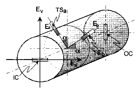
- figure 2 shows a cylindrical cavity with two orthogonal modes of
propagation, which includes two tuning screws in a direction rotated an angle
a
with respect to the fields that are propagated, and
- figure 3 shows the narrow-band equivalent circuit commonly employed
for the design of this type of filter.
DESCRIPTION OF AN IMPLEMENTATION OF THE INVENTION
A cavity filter of this type is formed by a number of resonant cavities
arranged one after the other and coupled through rectangular windows cut in
the
conductor that separates them.
Below is given a description of a filter of this type in which, for greater
simplicity, only one cylindrical type cavity has been used, the model being
perfectly applicable to a greater number of cavities.
This cavity is of a size that permits two modes of propagation along two
axes of polarization Ea and Ee perpendicular to each other. These axes of
polarization are fixed by the actual geometry of the cavity and by the tuning
elements.
The cavity also has input coupling means IC and output coupling means
OC which are windows or slots made in the faces perpendicular to the direction
of propagation. These windows permit, respectively, the excitation of the
cavity
by means of an input signal the direction of polarization of which is rotated
a '
certain angle a with respect to that of the propagation modes inside the
cavity,
and the extraction of the signal from the cavity in a direction of
polarization also
rotated 90 ° with respect to that of the excitation.
Figure 1 shows the equivalent circuit of the cavity described. The
behaviour of the modes of propagation a and b within the cavity, between its
input and output planes S2 and S3, can be modeled, respectively, using an
uncoupled two-port network.
Between the input and output planes of the 4-port network, S1 and S2,
each field is proportional to a certain standardised field pattern, Ea and Eb,
defined by the modes of propagation. Any field in the input and output planes,

2194071
-4-
S1 and S2, can be expressed as a linear combination of the aforementioned
standardised fields Ea and Ee. This type of breakdown is applicable to the
incident and reflected waves at all the ports.
Referring now to the exciting and extracting signal fields, E" and E", the
following relationship can be found:
E cosa sen a E _ E
CEx ) - sen a cosa E6 ) R(a~Eb
in which a represents the angle of rotation between the two directions of
polarization, that of the input and output signals and that of the propagation
modes inside the cavity.
This transformation relates the excitation patterns E" and E" with the
patterns of the resonant fields E, and Ee. The four-port network of figure 1
is
determined, in terms of the S parameters, for the incident and reflected waves
by the following expression:
0 ~'2 0
(S) - R(a~ 0 0 Sb" 0 Sb,2 RT (a~_ 0
~~0 ~ R(a~ Sa2, 0 Saz2 0 ~0~ ~RT (a)
0 Sb2, 0 Sbzz
in which Say and Sb9 are the S parameters of the two individual modes of
propagation and R(a) is the rotation vector matrix.
Dual-mode operation of the four-port network happens when a signal is
transmitted from one of the inputs 1,2 to both outputs 3 and 4.
By developing the last expression, it can be shown that this occurs when
sin a cos a (S6,2 - Sa,2) ~ 0. For this to happen, two conditions have to be
satisfied:
1.- the angle of rotation a has to be different from mrJ2, and
2.- the parameters Sb,2, Sa,2 have to be different (Sb,2 ~ Sa,2). This
condition implies that the electrical lengths of the two modes of propagation
are
different.
In other words, the cavity of figure 2 offers dual-mode resonance if both
modes are excited simultaneously and their resonances are tuned to different
frequencies f~ and f2.
As can be seen from figure 2, the angle of rotation a between the axes
of polarization of the input and output signals and the axes of the
polarization of
the cavity is 45 ° and the polarizations in the cavity are forced by
means of two

219477
-5-
small protuberances that are the actual tuning elements TSe and TSb which are
introduced into the cavity along two mutually perpendicular axes.
The matrix of the vector of rotation R(a) therefore becomes:
1 1
-1 1
By expanding the S parameters of the two modes in the four-port
network, the following expression is found:
0 0 S13 S14
- 0 ~ S14 S13
S13 S14
S14 S13
in which S13 = 2 (e ~~p + a >~b) and Si 4 = 2 ~e - ~~ b - a - J~ a ) .
By assuming that the effect of the tuning elements TSe and TSb is an
effective increase of the electrical length of the cavity, it is possible to
make
In a narrow-band approximation, the dual mode cavity can be associated
with the equivalent circuit of figure 3, commonly employed in filter
synthesis, in
which fo is the frequency of series resonance of the upper and lower branches
and k is the coupling coefficient between the two modes.
By idenfrfying the S parameters of both networks close to fo, the following
approximations are obtained:
f =2 fl*f2 and k~2f2 fl(-1)n when (f -f I«(f +f )/n7L
o fl + f2 fl + f2 2 1 1 2
This shows that the dual-mode cavity described above can be employed
for designing and tuning a filter by correcting the electrical dimensions by
modifying the effective length of the cavity by a whole multiple of one half-
wavelength at the resonant frequency fo and by acting on the tuning elements
TSe and TSb to achieve the resonant frequencies f, and f2 of each of the modes
a
and b in accordance with the desired values of fo and k of the synthesis
network.

Representative Drawing
A single figure which represents the drawing illustrating the invention.
Administrative Status

2024-08-01:As part of the Next Generation Patents (NGP) transition, the Canadian Patents Database (CPD) now contains a more detailed Event History, which replicates the Event Log of our new back-office solution.

Please note that "Inactive:" events refers to events no longer in use in our new back-office solution.

For a clearer understanding of the status of the application/patent presented on this page, the site Disclaimer , as well as the definitions for Patent , Event History , Maintenance Fee  and Payment History  should be consulted.

Event History

Description Date
Inactive: Expired (new Act pat) 2016-12-27
Inactive: Correspondence - MF 2010-08-10
Inactive: IPC from MCD 2006-03-12
Grant by Issuance 2004-11-02
Inactive: Cover page published 2004-11-01
Inactive: Final fee received 2004-08-18
Pre-grant 2004-08-18
Notice of Allowance is Issued 2004-05-14
Letter Sent 2004-05-14
Inactive: Approved for allowance (AFA) 2004-05-03
Amendment Received - Voluntary Amendment 2004-04-05
Inactive: S.30(2) Rules - Examiner requisition 2003-10-08
Inactive: Status info is complete as of Log entry date 2001-11-20
Letter Sent 2001-11-20
Inactive: Application prosecuted on TS as of Log entry date 2001-11-20
All Requirements for Examination Determined Compliant 2001-10-25
Request for Examination Requirements Determined Compliant 2001-10-25
Letter Sent 1999-07-26
Application Published (Open to Public Inspection) 1997-06-29

Abandonment History

There is no abandonment history.

Maintenance Fee

The last payment was received on 2003-11-18

Note : If the full payment has not been received on or before the date indicated, a further fee may be required which may be one of the following

  • the reinstatement fee;
  • the late payment fee; or
  • additional fee to reverse deemed expiry.

Patent fees are adjusted on the 1st of January every year. The amounts above are the current amounts if received by December 31 of the current year.
Please refer to the CIPO Patent Fees web page to see all current fee amounts.

Owners on Record

Note: Records showing the ownership history in alphabetical order.

Current Owners on Record
ALCATEL
Past Owners on Record
JOSE LUIS CACERES ARMENDARIZ
Past Owners that do not appear in the "Owners on Record" listing will appear in other documentation within the application.
Documents

To view selected files, please enter reCAPTCHA code :


To view images, click a link in the Document Description column. To download the documents, select one or more checkboxes in the first column and then click the "Download Selected in PDF format (Zip Archive)" or the "Download Selected as Single PDF" button.

List of published and non-published patent-specific documents on the CPD .

If you have any difficulty accessing content, you can call the Client Service Centre at 1-866-997-1936 or send them an e-mail at CIPO Client Service Centre.


Document
Description 
Date
(yyyy-mm-dd) 
Number of pages   Size of Image (KB) 
Representative drawing 1997-09-23 1 34
Abstract 1997-04-24 1 21
Description 1997-04-24 5 251
Claims 1997-04-24 1 28
Drawings 1997-04-24 1 42
Claims 2004-04-04 1 33
Representative drawing 2004-05-02 1 38
Courtesy - Certificate of registration (related document(s)) 1998-05-28 1 116
Reminder of maintenance fee due 1998-08-30 1 115
Reminder - Request for Examination 2001-08-27 1 129
Acknowledgement of Request for Examination 2001-11-19 1 179
Commissioner's Notice - Application Found Allowable 2004-05-13 1 161
Correspondence 1997-02-18 2 102
Correspondence 2004-08-17 1 23
Correspondence 2010-08-09 1 45