Language selection

Search

Patent 2194287 Summary

Third-party information liability

Some of the information on this Web page has been provided by external sources. The Government of Canada is not responsible for the accuracy, reliability or currency of the information supplied by external sources. Users wishing to rely upon this information should consult directly with the source of the information. Content provided by external sources is not subject to official languages, privacy and accessibility requirements.

Claims and Abstract availability

Any discrepancies in the text and image of the Claims and Abstract are due to differing posting times. Text of the Claims and Abstract are posted:

  • At the time the application is open to public inspection;
  • At the time of issue of the patent (grant).
(12) Patent: (11) CA 2194287
(54) English Title: METHOD FOR PRODUCING A CAP BAND FOR DISCHARGE LAMPS
(54) French Title: METHODE DE PRODUIRE UNE BANDE CAPACITIVE POUR LAMPES A DECHARGE
Status: Expired and beyond the Period of Reversal
Bibliographic Data
(51) International Patent Classification (IPC):
  • H1J 61/24 (2006.01)
  • H1J 9/395 (2006.01)
(72) Inventors :
  • WEINHARDT, EROLF (Germany)
(73) Owners :
  • PATENT-TREUHAND-GESELLSCHAFT FUER ELEKTRISCHE GLUEHLAMPEN MBH
(71) Applicants :
  • PATENT-TREUHAND-GESELLSCHAFT FUER ELEKTRISCHE GLUEHLAMPEN MBH (Germany)
(74) Agent: SMART & BIGGAR LP
(74) Associate agent:
(45) Issued: 2007-07-10
(86) PCT Filing Date: 1996-05-28
(87) Open to Public Inspection: 1997-01-03
Examination requested: 2003-01-09
Availability of licence: N/A
Dedicated to the Public: N/A
(25) Language of filing: English

Patent Cooperation Treaty (PCT): Yes
(86) PCT Filing Number: PCT/DE1996/000924
(87) International Publication Number: DE1996000924
(85) National Entry: 1997-01-02

(30) Application Priority Data:
Application No. Country/Territory Date
195 21 972.4 (Germany) 1995-06-16

Abstracts

English Abstract


The invention concerns a process for manufacturing a cap strip (4) for
discharge lamps, whereby a carrier strip (1) is coated with at
least one substance destined for introduction into the discharge lamp, in
particular a mercury alloy (2) and/or getter substance (3). According
to the invention, a section (5) is detached from the carrier strip (1) at
right angles to the strip's length. The section forms the discharge
lamp cap strip (4) and is coated over its entire width (bt) with the
substance(s) in question.


French Abstract

L'invention concerne un procédé de fabrication d'une bande de rallonge (4) pour lampes à décharge, selon lequel une bande support (1) est recouverte d'au moins un matériau à introduire dans la lampe à décharge, notamment un alliage de mercure (2) et/ou un matériau getteur (3). Selon l'invention, une section (5) est séparée de la bande support (1) transversalement par rapport à son sens longitudinal. Cette section (5) constitue la bande de rallonge (4) d'une lampe à décharge et est recouverte sur toute sa largeur (bt) du matériau en question.

Claims

Note: Claims are shown in the official language in which they were submitted.

CLAIMS:
1. Method for producing a cap band for discharge
lamps, a carrier band (1) being coated with at least one
material, in particular a mercury alloy (2) or getter
material (3), to be introduced into a discharge lamp,
characterized in that there is separated from the carrier
band (1) at right angles to its longitudinal direction (LB)
a segment (5) which forms a cap band (4) or a part of a cap
band for a discharge lamp and is coated over its entire
width (BT) with the at least one material, the transverse
direction for the carrier band becoming the longitudinal
direction for the segment used as cap band or part of the
cap band.
2. Method according to Claim 1, characterized in that
the carrier band (1) has a width (BB) which is equal to the
circumference of an annular cap of the discharge lamp.
3. Method according to Claim 1, characterized in that
the cap band is produced by one-sided coating of the carrier
band (1) with the at least one material to be introduced
into the discharge lamp.
4. Method according to Claim 1, characterized in that
the cap band is produced by two-sided coating of the carrier
band (1) with at least two materials to be introduced into
the discharge lamp, the cap band being coated on one side
with the at least one material to be introduced into the
discharge lamp and being coated on the other side with the
at least one further material to be introduced into the
discharge lamp.
6

5. Method according to any one of claims 1 to 4,
characterized in that coating is done with a mercury alloy
or with getter.
6. Method according to any one of claims 1 to 5,
characterized in that the carrier band (1) has a width (BB)
in the range of about 12 to 55 mm.
7. Method according to any one of claims 1 to 6,
characterized in that the carrier band (1) is coated in such
a way that the cap band (4) intended for a discharge lamp
has the quantity of the material or materials intended for
this discharge lamp.
8. Method for producing a discharge lamp, in which a
segment (5) is cut from a carrier band (1) which is coated
with at least one material, in particular a mercury alloy or
a getter material, to be introduced into the discharge lamp,
which segment (5) is inserted into the discharge lamp and
fastened therein, characterized in that the segment (5) is
separated from the carrier band (1) at right angles to its
longitudinal direction (LB) and the segment (5) forms a cap
band (4) or a part of a cap band for the discharge lamp and
is coated over its entire width (BT) with the at least one
material, the transverse direction for the carrier band (1)
becoming the longitudinal direction for the segment (5) used
as the cap band (4) or part of the cap band.
7

Description

Note: Descriptions are shown in the official language in which they were submitted.


~
~ ~~~~ ~~r-
'
METHOD FQR PRfSD'UCING A CAP BAND FQE DISCFi.a,RGE LAMPS
The invention relates to a r-ethod for producing a cap band
for discharge lamps as generically defined by the preamble to
claim 1 and to a cap band as qene,rically defined by the preamble
to claim 8.
From Published, CTnexamined Japanese Patent Application 6-
96728, a low-pressure nercury vapor discharge lamp is known. This
discharge lamp has aretal ring cap, which comprises two metal
ring portions, in which one portion has a mercury-dispensing
functican while the other metal portion has no such function. The
first of these metal. portions comprises a nickel-coated iron
substrate and a mercury alloy, which comprises a mercury-titanium
alloy powder applied to the substrate.
The mercury alloy is located on one side, the inside of the
ring portion, while getter is located on the other side, the
outside of the ring portion. The amount of mercury to be
introduced into the discharge lamp is determined by varying the
length of the first portion. That is, if the amount of mercury is
to be increased, the length of the first metal portion mentioned
above is increased.
The ring cap of the previously known discharge lamp is
accordingly not embodied in one piece but rather comprises a
plurality of components. This increases both the costs of
production of the ring cap and the costs of production of the
discharge lamp.
With this prior art as the point of departure, the object
of the invention is to disclose a method of the type referred to
at the outset and a cap band that makes more-economical production
possible.
According to the invention, this object is attained by a
~ ;3123S I~OiS'rJ~Nl3~ t1J :Nr Lw~2'~:ZZ9 69 5t7f ~-idd .~Jtf~SO : tJO~ ~ OC
~S ~ ~ ~ ~~~J-6Z

CA 02194287 2006-02-20
27813-62
method for producing a cap band for discharge lamps, a
carrier band (1) being coated with at least one material, in
particular a mercury alloy (2) or getter material (3), to be
introduced into a discharge lamp, characterized in that
there is separated from the carrier band (1) at right angles
to its longitudinal direction (LB) a segment (5) which forms
a cap band (4) or a part of a cap band for a discharge lamp
and is coated over its entire width (BT) with the at least
one material, the transverse direction for the carrier band
becoming the longitudinal direction for the segment used as
cap band or part of the cap band.
The invention has the advantage that from a
predetermined length of cap band produced by the method of
the invention, many portions can be made, and each portion
can be processed in a simple way, in particular to make a
one-piece ring cap.
For instance, the width of the substrate band used
in the method of the invention is approximately 12 to 55 mm.
If one assumes that for a ring cap a 5-millimeter-wide cap
band should be provided, then from one running meter of
substrate band, 200 cap bands can be made by the method of
the invention; that is, 199 cuts are required. In the prior
art, in which a substrate band has a width of 5 to 7 mm,
only 23 cap bands can be made for one full ring cap
circumference of 42 mm.
The application of getter and mercury alloy is
multiple times more expensive than the material itself. If
according to the invention cutting is done crosswise to the
application of material, and moreover coating is done on one
side, then the production speed for one portion (cap band)
2

CA 02194287 2006-02-20
27813-62
is multiple times greater (depending on the width BT, Figs.
3, 4), for the same machine speed.
In a further advantageous embodiment of the method
of the invention, the cap band is produced by coating the
substrate band on one side with the at least one material to
be introduced into the discharge lamp, and in particular
with two materials namely with a mercury alloy and getter.
This has the advantage, among others, that the coating of
the two materials on the substrate band can be done
simultaneously.
In accordance with a further aspect of this
invention, there is provided a method for producing a
discharge lamp, in which a segment (5) is cut from a carrier
band (1) which is coated with at least one material, in
particular a mercury alloy or a getter material, to be
introduced into the discharge lamp, which segment (5) is
inserted into the discharge lamp and fastened therein,
characterized in that the segment (5) is separated from the
carrier band (1) at right angles to its longitudinal
direction (LB) and the segment (5) forms a cap band (4) or a
part of a cap band for the discharge lamp and is coated over
its entire width (BT) with the at least one material, the
transverse direction for the carrier band (1) becoming the
longitudinal direction for the segment (5) used as the cap
band (4) or part of the cap band.
The invention will now be described in conjunction
with the drawing.
2a

2194287
Shown are:
Fig. 1, a ring cap for a discharge lamp of the prior art;
Fig. 2, a cap band of the prior art;
Fig. 3, a first embodiment of a cap band, produced by the
method of the invention, coated on both sides;
Fig, 4, a second embodiment of a cap band, produced by the
method of the invention, coated on one side; and
Figs. 5 and 6, two exemplary embodiments of a ring cap
produced from a cap band according to the invention.
The ring cap shown in Fig. 1 for a discharge lamp comprises
a two-piece oval ring 30, which comprises a first metal piece 31
and a second metal piere 32. The first metal piece may be formed
by a cap band, which is shown in Fig. 2.
In Fig. 3, an exemplary embodiment of a cap band produced
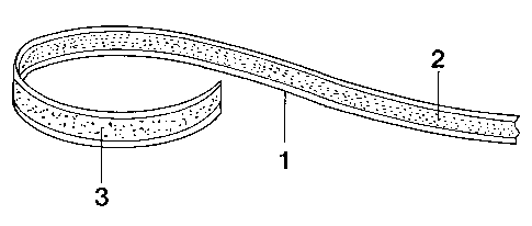
by the rriethod of the invention is shown. A substrate band 1
(metal band), which has the length LB, is coated with at least one
materiai. to be intrgduced, particularly by heating, into the
discharge lamp. Preferably, the substrate band 1, which for
i.nstance comprises nickel-coated sheet iron, is coated with a
mercury alloy 2 and/or getter material. 3, for instance by rolling.
The widtb BB of the substrate band 1 is selected such that it is
egual to the circumference of the respective ri*ig cap of the
discharge lamp.
The c;a.p band 4 produced by the method of the invention may
be formed by one-sided or two-sided coating of the substrate band.
Examples for these embodiments of the cap band are shown in Figs.
3 and 4. Fig. 3 shows a cap band in which the substrate band 1 is
coated on one side with getter material 3 and on the other side
with a mercury alloy 2. A portion 5 that forms the cap band 4 for
a disCharge lamp is sever_efl from the substrate band 1 transversely
-3-
b%-G1iGti Nul563'r11L_- UD:'it1 _Z222?29 58 5b+ W-1d.d 0;~dSO:hd7l OC tS v?
730 b?

21 M87
to its longitudi.nal direction LB (which as a rule is the sdirection
in which the m.aterial is applied). The portion 5 or cap band 4 is
coated over its entire width BT with at least one material.
The cap band produced by the method of the invention has a
length LT in the rar.ge of approximately 12 to 55 mm, for instance.
The respective length. LT, as already noted, is equivalent to the
circumference of t:.e respect3_ve ring cap of the discharge lamp
(for instance, 48 mrr, for a TS low-pressure mercury vapor discharge
lamp with a diameter_ of 8/8 ;nches).
The cap t,and slzcrdm in Fig. 4, produced by the method of the
invention, is coated on one s::de> Getter material and the mercury
alloy are accordingly located on the same sid.e of the cap band.
The cap band shown in Fig. 4 has a width of 44 r,m.
In Figs. 3 and 4, a portion 5 that is 5 mm in width is
shown on the riqht-hand side of the substrate band 4 of each
drawing. According to the invention, from the running substrate
band, for instance as it is shown in Fig. 3 and 4, portions 5 are
cut, eacri, having a width BT of 5 mm (length LT of the portion 5
width BB of the substrate band 1-- circ:uraference of the ring cap =
44 mm). By the determination of the width 87C of the portion, in
the present case 5 mm, the quantity of material (mercury alloy
and/or getter) to be introduced by heating into the discharge lamp
is determined. On the other hand, the quantity of material ts) be
applied per unit of length of substrate band is deterinir;e.d with a
view to a possible fixed width BT of the cap band.
A cap band produced by the method of the invention as
described is use.d to produce a discharge lamp, in such a way that
it is introdaced into the discharge lamp and sec:ured therein.
According to the invention, this cap band has a length that
is ecrial to the circumference of a ring cap of the discharge larip
-4-
~~ h3 F7+ V~-Ltd wHdSO:rao') i!a t-s:77 ??a-Fti

219 42 57
(such as 44 ?nm). The width of the portion or of the cap band is 5
mm, for instance, and this width is chosen as a function of the
material to be introduced into the discharge lamp. Accordingly,
the substrate band is coated in such a way that the quantity of
material oh materials intended for the discharge lamp is applied
over a substrate band portion that is intended for a discharge
lamp and has a predetermined width BT, for instance of 5 to 7 mm.
The portion is optionally curved into the specified shape,
introduced into the discharge lamp, and secured there.
A discharge lamp according to the invention thus has a cap
band 4 of the kind described above and claimed.
ihe ring cap shown in Fig. 5 comprises solely a cap band 4
according to the invention, which is welded on its ends, while the
ring cap shown in Fig. 6 comprises one cap band according to the
irventi.on and one fuz-ther band, the cap band 4 and the further
band being welded to one another.
-5-
3'~ ~ ~1I35 ~J01~~3H1~ tJ 'Ntj LZCZELc _ 63 5'+ W- ltd ~dt~Z57 ~~JC ~ UC] f7S
; I 4 Z-70- 6I

Representative Drawing
A single figure which represents the drawing illustrating the invention.
Administrative Status

2024-08-01:As part of the Next Generation Patents (NGP) transition, the Canadian Patents Database (CPD) now contains a more detailed Event History, which replicates the Event Log of our new back-office solution.

Please note that "Inactive:" events refers to events no longer in use in our new back-office solution.

For a clearer understanding of the status of the application/patent presented on this page, the site Disclaimer , as well as the definitions for Patent , Event History , Maintenance Fee  and Payment History  should be consulted.

Event History

Description Date
Time Limit for Reversal Expired 2015-05-28
Letter Sent 2014-05-28
Grant by Issuance 2007-07-10
Inactive: Cover page published 2007-07-09
Inactive: Final fee received 2007-04-17
Pre-grant 2007-04-17
Notice of Allowance is Issued 2006-10-20
Letter Sent 2006-10-20
4 2006-10-20
Notice of Allowance is Issued 2006-10-20
Inactive: Approved for allowance (AFA) 2006-07-24
Amendment Received - Voluntary Amendment 2006-02-20
Inactive: S.30(2) Rules - Examiner requisition 2006-01-04
Amendment Received - Voluntary Amendment 2005-07-05
Inactive: S.30(2) Rules - Examiner requisition 2005-01-05
Amendment Received - Voluntary Amendment 2004-07-20
Inactive: Application prosecuted on TS as of Log entry date 2003-02-18
Letter Sent 2003-02-18
Inactive: Status info is complete as of Log entry date 2003-02-18
Amendment Received - Voluntary Amendment 2003-02-10
All Requirements for Examination Determined Compliant 2003-01-09
Request for Examination Requirements Determined Compliant 2003-01-09
Application Published (Open to Public Inspection) 1997-01-03

Abandonment History

There is no abandonment history.

Maintenance Fee

The last payment was received on 2007-04-20

Note : If the full payment has not been received on or before the date indicated, a further fee may be required which may be one of the following

  • the reinstatement fee;
  • the late payment fee; or
  • additional fee to reverse deemed expiry.

Patent fees are adjusted on the 1st of January every year. The amounts above are the current amounts if received by December 31 of the current year.
Please refer to the CIPO Patent Fees web page to see all current fee amounts.

Owners on Record

Note: Records showing the ownership history in alphabetical order.

Current Owners on Record
PATENT-TREUHAND-GESELLSCHAFT FUER ELEKTRISCHE GLUEHLAMPEN MBH
Past Owners on Record
EROLF WEINHARDT
Past Owners that do not appear in the "Owners on Record" listing will appear in other documentation within the application.
Documents

To view selected files, please enter reCAPTCHA code :


To view images, click a link in the Document Description column (Temporarily unavailable). To download the documents, select one or more checkboxes in the first column and then click the "Download Selected in PDF format (Zip Archive)" or the "Download Selected as Single PDF" button.

List of published and non-published patent-specific documents on the CPD .

If you have any difficulty accessing content, you can call the Client Service Centre at 1-866-997-1936 or send them an e-mail at CIPO Client Service Centre.


Document
Description 
Date
(yyyy-mm-dd) 
Number of pages   Size of Image (KB) 
Representative drawing 1997-06-08 1 6
Cover Page 1998-06-15 1 19
Cover Page 1996-05-27 1 19
Abstract 1996-05-27 1 46
Description 1996-05-27 5 212
Claims 1996-05-27 3 89
Drawings 1996-05-27 2 37
Representative drawing 2004-12-09 1 9
Claims 2005-07-04 2 78
Description 2005-07-04 6 236
Claims 2006-02-19 2 70
Description 2006-02-19 6 249
Cover Page 2007-06-20 1 39
Reminder of maintenance fee due 1998-01-28 1 111
Reminder - Request for Examination 2003-01-28 1 112
Acknowledgement of Request for Examination 2003-02-17 1 173
Commissioner's Notice - Application Found Allowable 2006-10-19 1 161
Maintenance Fee Notice 2014-07-08 1 170
PCT 1997-01-01 11 428
Correspondence 2007-04-16 1 41
International preliminary examination report 1997-01-01 4 137