Language selection

Search

Patent 2194508 Summary

Third-party information liability

Some of the information on this Web page has been provided by external sources. The Government of Canada is not responsible for the accuracy, reliability or currency of the information supplied by external sources. Users wishing to rely upon this information should consult directly with the source of the information. Content provided by external sources is not subject to official languages, privacy and accessibility requirements.

Claims and Abstract availability

Any discrepancies in the text and image of the Claims and Abstract are due to differing posting times. Text of the Claims and Abstract are posted:

  • At the time the application is open to public inspection;
  • At the time of issue of the patent (grant).
(12) Patent: (11) CA 2194508
(54) English Title: A BAG BUFFER
(54) French Title: DISPOSITIF AMORTISSEUR DE CHOCS POUR SAC
Status: Expired and beyond the Period of Reversal
Bibliographic Data
(51) International Patent Classification (IPC):
  • A45C 13/02 (2006.01)
  • A45C 05/00 (2006.01)
  • B65D 81/107 (2006.01)
(72) Inventors :
  • LEE, YOUN-JAE (Republic of Korea)
(73) Owners :
  • JINWOONG LTD.
(71) Applicants :
  • JINWOONG LTD. (Republic of Korea)
(74) Agent: MARKS & CLERK
(74) Associate agent:
(45) Issued: 1999-09-21
(22) Filed Date: 1997-01-07
(41) Open to Public Inspection: 1998-05-06
Examination requested: 1997-01-07
Availability of licence: N/A
Dedicated to the Public: N/A
(25) Language of filing: English

Patent Cooperation Treaty (PCT): No

(30) Application Priority Data:
Application No. Country/Territory Date
96-52290 (Republic of Korea) 1996-11-06

Abstracts

English Abstract


A bag buffer is applied to a bag, the bag buffer
consisting of two plates, springs, and a sponge, the
springs and the sponge being disposed between the two
plates, such that the bag buffer can effectively buffer
outside shocks to protect articles contained in the bag
as well as to easily carry and use the articles.


French Abstract

Dispositif amortisseur de chocs pour sac. Le dispositif se compose de deux plaques, de ressorts et d'une éponge, les ressorts et l'éponge étant situés entre les deux plaques pour permettre au dispositif d'amortir efficacement les chocs afin de protéger les articles contenus dans le sac. Il facilite donc le transport de ces articles et son utilisation est simple.

Claims

Note: Claims are shown in the official language in which they were submitted.

3
THE EMBODIMENTS OF THE INVENTION IN WHICH AN EXCLUSIVE
PROPERTY OR PRIVILEGE IS CLAIMED ARE DEFINED AS FOLLOWS:
1. A shock absorbing bag having front, rear, left, right, top and bottom
sides, comprising:
at least one buffer mounted on one of said bottom, left and right sides,
said at least one buffer comprising:
two planar elements disposed parallel to the corresponding side;
a first elastic member disposed between said two planar elements, said
first elastic member having at least one hole extending through the first
elastic
member, a central axis of the at least one hole being perpendicular to each of
said
planar elements; and
at least one second elastic member snugly inserted into the at least one
hole, said at least one second elastic member having an elastic constant
higher than
that of said first elastic member.
2. The shock absorbing bag according to claim 1, wherein said first
elastic member is made of a material selected from the group consisting of a
sponge.
3. The shock absorbing bag according to claim 1, wherein said at least
one second elastic member is a metal spring.
4. The shock absorbing bag according to claim 1, wherein said at least
one second elastic member is a coil spring.
5. The shock absorbing bag according to claim 1, wherein said at least
one hole comprises a cylindrical hole.

Description

Note: Descriptions are shown in the official language in which they were submitted.


21 8450 8
A BAG BUFFER
BACKGROUND
The present invention relates to a bag buffer, and more particularly to a
bag buffer so as to keep shock-sensitive articles (i.e. notebook computers) in
safety,
and to carry and use easily.
Conventionally, to protect articles contained in bags from outside
shocks during carrying or keeping, shock-absorbenting material like sponge is
thinly
installed on the inner surface of a bag, or articles are wrapped in shock-
absorbing
1 o wrapper.
However, thin sponge installed in a bag cannot safety protect articles
from severe outside shocks. Furthermore, wrapping articles with shock-
absorbing
wrapper is difficult to apply where the articles are frequently taken out for
use like
notebook computers.
SUMMARY
It is therefore an object of an aspect of the present invention to
overcome the above-described prior art drawbacks and to provide a bag buffer
enabling to keep shock-sensitive articles contained in the bag safely in a new
manner
2o as well as to carry and use easily, differing from methods of the prior
art, and the
assembly thereof.
According to the present invention there is provided a shock absorbing
bag having front, rear, left, right, top and bottom sides, comprising:
at least one buffer mounted on one of said bottom, left and right sides,
said at least one buffer comprising:
two planar elements disposed parallel to the corresponding side;
a first elastic member disposed between said two planar elements, said
first elastic member having at least one hole extending through the first
elastic
member, a central axis of the at least one hole being perpendicular to each of
said
3o planar elements; and
at least one second elastic member snugly inserted into the at least one
hole, said at least one second elastic member having an elastic constant
higher than
that of said first elastic member.
a

2
a1 9450 8
BRIEF DESCRIPTION OF DRAWINGS
Further objects and other advantages of the present invention will
become apparent from the following description in conjunction with the
attached
drawings, in which:
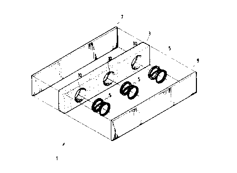
Fig. 1 is an exploded perspective view of a bag buffer in accordance
with a preferred embodiment of the present invention;
Fig. 2 is a perspecitve view of a bag buffer in accordance with a
preferred embodiment of the present invention is applied; and
Fig. 3 is a sectional view of a bag buffer in accordance with a preferred
1 o embodiment of the present invention.
DESCRIPTION
Referring to Fig. 1, there is shown an exploded perspective view of a
bag buffer in accordance with a preferred embodiment of the present invention,
in
which reference numeral 1 indicates a bag buffer.
As shown in Figs. 1 and 3, a bag buffer 1 comprises springs 5 as a first
buffer member and a sponge 3 as a

219450 8
second buffer member, all of which are installed between
two plates 7 and 9 and combined with each other at the
same time. The first buffer member 5 has elastic
constants higher than that of the second buffer member
3.
In this embodiment, there is provided three
circular holes 10 in the sponge 3 such that springs 5
can snugly be placed in the circular holes 10
respectively. The sponge 3 incorporated with the
springs 5 is disposed between two plates 7 and 9.
Fig. 2 a perspective view of a bag in which a bag
buffer 1 for a bag in accordance with a preferred
embodiment of the present invention is applied, while
Fig. 3 is a sectional view of a bag buffer 1 for a bag
according to a preferred embodiment of the present
invention, in which a bag buffer l is installed in the
inner surface of a bottom side, a top side, a left aide,
and a right side respectively, thus forming an inner
peripheral edge, and being covered with covering
material 11.
As described above, a bag buffer 1 for a bag is
installed to form an inner peripheral edge, since an
edge of a flat object generally touches the bottom first
than a wide surface of the object when a flat object is
dropped. If necessary, a bag buffer can be installed in
all planes of a bag.
Therefore, if outside shocks are transmitted to a
3

.. 21 84508
one aide of a bag buffer 1 (i.e:, one of two plates 7
and 9), the shocks are first buffered by springs 5 of
the first buffer member having relatively higher elastic
constants and then gradually reduced by a sponge 3 of
the second buffer member having relatively lower elastic
constants simultaneously, thereby effectively buffering
outside shocks transmitted to articles contained in a
bag.
Although a preferred embodiment of the present
invention has been described in detail hereinabove, it
should be clearly understood that many variations and/or
modifications of the basic inventive concepts herein
taught which may appear to those skilled in the present
art will still fall within the spirit and scope of the
present invention, as defined in the appended claims.
4

Representative Drawing
A single figure which represents the drawing illustrating the invention.
Administrative Status

2024-08-01:As part of the Next Generation Patents (NGP) transition, the Canadian Patents Database (CPD) now contains a more detailed Event History, which replicates the Event Log of our new back-office solution.

Please note that "Inactive:" events refers to events no longer in use in our new back-office solution.

For a clearer understanding of the status of the application/patent presented on this page, the site Disclaimer , as well as the definitions for Patent , Event History , Maintenance Fee  and Payment History  should be consulted.

Event History

Description Date
Inactive: IPC deactivated 2011-07-29
Inactive: IPC from MCD 2006-03-12
Time Limit for Reversal Expired 2001-01-08
Letter Sent 2000-01-07
Grant by Issuance 1999-09-21
Inactive: Cover page published 1999-09-20
Inactive: Final fee received 1999-06-24
Pre-grant 1999-06-24
Notice of Allowance is Issued 1999-04-29
Letter Sent 1999-04-29
Notice of Allowance is Issued 1999-04-29
Inactive: Status info is complete as of Log entry date 1999-04-27
Inactive: Application prosecuted on TS as of Log entry date 1999-04-27
Inactive: Approved for allowance (AFA) 1999-04-22
Application Published (Open to Public Inspection) 1998-05-06
Request for Examination Requirements Determined Compliant 1997-01-07
All Requirements for Examination Determined Compliant 1997-01-07

Abandonment History

There is no abandonment history.

Maintenance Fee

The last payment was received on 1998-12-15

Note : If the full payment has not been received on or before the date indicated, a further fee may be required which may be one of the following

  • the reinstatement fee;
  • the late payment fee; or
  • additional fee to reverse deemed expiry.

Patent fees are adjusted on the 1st of January every year. The amounts above are the current amounts if received by December 31 of the current year.
Please refer to the CIPO Patent Fees web page to see all current fee amounts.

Fee History

Fee Type Anniversary Year Due Date Paid Date
Registration of a document 1997-01-07
MF (application, 2nd anniv.) - standard 02 1999-01-07 1998-12-15
Final fee - standard 1999-06-24
Owners on Record

Note: Records showing the ownership history in alphabetical order.

Current Owners on Record
JINWOONG LTD.
Past Owners on Record
YOUN-JAE LEE
Past Owners that do not appear in the "Owners on Record" listing will appear in other documentation within the application.
Documents

To view selected files, please enter reCAPTCHA code :


To view images, click a link in the Document Description column. To download the documents, select one or more checkboxes in the first column and then click the "Download Selected in PDF format (Zip Archive)" or the "Download Selected as Single PDF" button.

List of published and non-published patent-specific documents on the CPD .

If you have any difficulty accessing content, you can call the Client Service Centre at 1-866-997-1936 or send them an e-mail at CIPO Client Service Centre.


Document
Description 
Date
(yyyy-mm-dd) 
Number of pages   Size of Image (KB) 
Claims 1999-04-13 1 34
Description 1999-04-13 4 123
Abstract 1997-04-27 1 10
Description 1997-04-27 4 112
Claims 1997-04-27 1 16
Drawings 1997-04-27 3 66
Representative drawing 1998-05-21 1 11
Representative drawing 1999-09-12 1 13
Reminder of maintenance fee due 1998-09-08 1 115
Commissioner's Notice - Application Found Allowable 1999-04-28 1 164
Maintenance Fee Notice 2000-02-06 1 178
Correspondence 1999-06-23 1 49
Fees 1998-12-14 1 53
Prosecution correspondence 1997-01-06 9 315
Prosecution correspondence 1997-11-09 3 75
Prosecution correspondence 1999-01-06 2 67
Examiner Requisition 1998-08-10 2 47
Courtesy - Office Letter 1997-02-03 1 38