Note: Descriptions are shown in the official language in which they were submitted.
W 0 95125583 PCT1US95/03431
' VAPOR-.T~TOUTD CONTACT A P~RnTUB
H~CKGROUND OF THE INVENTION
This invention relates to liquid contact
.
apparatus used in chemical processing, and particularly
to such apparatus in which a vessel contains a plurality
of substantially horizontal trays which support a vapor-
liquid-mixture. In apparatus of this type, liquid is
introduced at the upper end of the vessel and it flows
l0 down from tray-to-tray, via downcomers. The trays are
apertured to provide bubble areas through which ascending
vapors can rise to contact liquid and/or vapor-liquid
mixtures which are supported on and flowing across the
respective trays.
There have been many proposals for improving
contact apparatus of this type. However, significant
features of the apparatus disclosed in this specification
are believed to represent new approaches to the design
and construction of such apparatus.
Chuang et al. U.S. patent 4,504,426 shows gas-
liquid contacting apparatus in which downcomers have
apertured lower outlet walls. These downcomers, however,
discharge directly over apertured areas of the deck
therebelow. Such an arrangement can result in
undesirable jetting of liquid down from the downcomer
apertures through the apertures in the deck therebelow,
thus bypassing two subsequent trays and reducing the
performance of the apparatus.
A downcomer with an apertured outlet wall
positioned over an elevated downcomer seal area is shown
in Bentham U.S. patent 4,550,000. Bentham also has
apertures in the elevated downcomer seal area, and this
is believed to be detrimental from the standpoint of tray
performance.
WO 95125583 PCTIUS95103431
- 2 -
In U.S. patent 4,956,127 issued to Binkley et
al., Fig. 8 shows a downcomer with an apertured outlet
wall, but the downcomer seal area is provided with gas
introducing openings located directly beneath a downcomer
outlet. Binkley et al. also disclose a channel beam
truss which directly supports an elevated upstream panel
provided with the downcamer seal area. However, the
channel truss is positioned where it inherently obstructs
the horizontal flow of gas immediately beneath the truss-
supported tray.
sUME~L~-T:Y OTr '~'HE T~tvw~~~rOlQ
This invention relates to improvements in
vapor-liquid contact apparatus of the type comprising a
vessel, a plurality of substantially horizontal trays
mounted in the vessel in vertically spaced relation to
support a vapor-liquid mixture, and downcomer passages
extending down from the trays. In a known manner, the
downcomer passages are arranged to receive a vapor-liquid
mixture from one tray and to release liquid onto a
subsequent tray therebelow.
One aspect of the invention pertains to such
apparatus in which each of said trays having a downcomer
seal area, an overflow weir, and a bubble area which lies
between the downcomer seal area and the overflow weir.
The bubble area has apertures which permit ascending
vapors to flow into the vapor-liquid mixture on the tray.
The downcomer passage has a lower outlet end which
overlies and is horizontally coextensive with a downcomer
seal area of the subsequent tray. The novel combination
of features in such an apparatus are as follows:
(a) each of the downcomer passages has a
bottom wall which is substantially
WO 95125583 ~ ~ 9 4 5 8 0 fCT~S95/03431
- 3 -
horizontal and is provided with apertures
for regulating the effective head of fluid
in the downcomer passage,
(b) the downcomer seal area is substantially
devoid of apertures so as to prevent
ascending vapors from affecting the flow
in a preceding downcomer passage of a tray
thereabove and to prevent fluid in the
preceding downcomer passage from weeping
through the downcomer seal area; and
(c) the downcomer seal area and an upstream
portion of said bubble area are elevated
with respect to a major portion of the
tray's upper surface area.
Preferably, the trays are spaced vertically
from each other by a distance ~, and each of said
downcomer passages has its lower outlet end between a
minimum elevation which is at least H/24 higher than the
weir of the subsequent tray and a maximum elevation which
is a distance H/3 above the downcomer seal area of the
subsequent tray. This elevation of the outlet prevents
excessive horizontal velocity of fluid where it flows
from the downcomer seal area to the bubble area of the
tray. The downcomer seal area and the upstream portion
of said bubble area are on an upstream panel, and the
upstream portion of the bubble area is from 10% to 40% of
the bubble area of the tray. The main portion of the
upstream panel is elevated with respect to said arcuate
margin portion on the upstream panel. Additionally or
alternatively, the apparatus can include a shim which
lies beneath the arcuate margin portion to elevate the
upstream panel.
The bottom wall of the downcomer has an arcuate
edge and a linear edge, and the area occupied by the
wo 9sizsss3 2 ~ 9 q. 5 ~ 0
PCT/iTS95103431
- 4 -
apertures in the bottom wall of the downcomer is greater
near the arcuate edge than near the linear edge.
In another respect, the invention involves a '
construction in which each tray is formed of a plurality
of panels including two downstream panels which are
laterally spaced apart and have downstream portions of
the bubble area formed i.n them. These downstream panels
each have a horizontal deck portion with an edge which
has an integral flange extending downwardly therefrom.
Each integral flange has a lower end provided with a
horizontal web. The apparatus has a stationary truss
which supports the upstream ends of said integral
flanges. The stationary truss is spaced below the
horizontal deck portions. to provide an open area which
permits vapors to flow between the truss and the deck
portions.
Preferably, the truss has a web and flanges
which extend from the web in a substantially horizontally
direction which is upstream with respect to the tray
therebelow so as to capture and laterally disperses part
of the liquid froth or spray which is moving in a
downstream direction on the tray therebelow. There is a
third downstream panel which has a side margin which
overlies and is supported by at least one of the
downstream panels. The 'third downstream panel having a
main portion which includes part of said bubble area, and
the third downstream panel has its side margin elevated
with respect to its main portion.
According to a further feature of the
invention, a corrugated sheet is positioned vertically in
a downcomer passage. The corrugated sheet has
corrugations which form ridge and recesses, and the
corrugated sheet has at least one surface which is
exposed to and openly faces the vapor-liquid mixture in
35. the downcomer passage to promote deentrainment of vapor
ro
W095125583 ~ PCT/US95/03431
- 5 -
' from liquid in the mixture. The corrugations are
inclined to position their ridges and recesses at an
angle to the flow of liquid-vapor mixture in the
downcomer passage so that the ridges reduce the local
velocity, of the mixture and the recesses provide channels
for upward inclined flow of vapor which becomes
deentrained from the mixture.
Preferably, the corrugations are inclined at an
angle of about 45°. However, this angle may range from
20° to,70° from the horizontal. The corrugations are
arranged in two sets of corrugations which extend
upwardly and outwardly on the sheet. The corrugated
sheets can be perforated to permit some pressure
equalization across them.
$I~TEF DESCRTPTTON OF T E D~n,NTyGB
Fig. 1 is a perspective view of one tray
constructed according to the invention.
Fig. 2 is a plan view of a tray according to
the invention, mounted in a vessel.
Fig. 3 is a diagrammatic sectional view of a
tray in the vessel, as seen along the line 3-3 in Fig. 2.
Fig. 4 is a view of the bottom wall of a
downcomer in an apparatus constructed according to the
invention.
Fig. 5 is a diagrammatic sectional view of
three trays constructed according to the invention,
mounted in a vessel.
Fig. 6 shows a preferred configuration of a
1
tray opening.
Fig. 7 shows a portion of a corrugated sheet of
the type which is mounted in a downcomer according to one
feature. of the invention.
Fig. 8 shows a full corrugated sheet which is
suited for mounting in a downcomer.
WO 95/25583
PCT/ITS95/03431
- 6 -
PE80RTP'~'TON OF A PREFERRED Fxaenpr~;p~A~
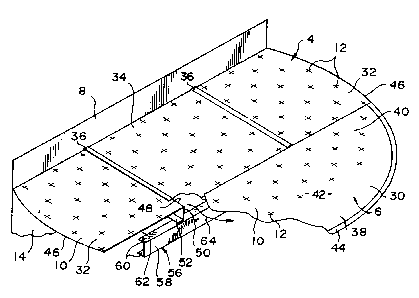
As shown in Figs. 2, 3, and 5, the complete
apparatus includes a vessel 2 which contains a plurality '
of substantially horizontal trays 4 for supporting a
vapor-liquid mixture. 7:.iquid is introduced at the upper
end of the vessel and it flows down from tray-to-tray
where it is contacted by ascending vapors which are
introduced at the lower end of the vessel.
The trays are vertically spaced from each
other. Each tray has a downcomer seal area 6, an
overflow weir 8, and a bubble area 10 which lies between
the downcomer seal area 6 and the overflow weir- 8. The
downcomer seal area is elevated with respect to a major
portion of the tray s upper surface area.
The bubble area 10 has apertures represented
schematically by plus signs ("+o~) 12 which permit
ascending vapors to flow into the vapor-liquid mixture on
the tray. A downcomer wall 14 is attached to and extends
down from each weir to provide a downcomer passage 16
which carries liquid from the downstream end of one tray
to the downcomer seal area 6 of the next lower tray. The
lower outlet end of the downcomer passage 16 overlies and
is substantially coextensive with the downcomer seal area
6 of the next lower tray.
The downcomer seal area 6 is substantially
devoid of any apertures. This prevents ascending vapors
from affecting the fluid flow in the downcomer passage 16
above the downcomer seal area, and it also prevents fluid
in the downcomer passage from weeping through the
downcomer seal area 6. The latter characteristic is
particularly important because any weepage through the
downcomer seal area significantly affects performance
because it permits the fluid to bypass two trays.
At the lower end of each downcomer passage 16,
there is a bottom wall 18 which is substantially
CA 02194580 2006-03-14
-7_
horizontal and is provided with apertures 25 for regulating the effective head
of fluid in the
downcomer passage 16. These apertures may have any suitable size and shape.
For example,
they may be square or round holes which each have an area no greater than
about one square
inch (6.45 square centimeters). Their total area can be from 10 to 50% of the
horizontal area
at the top of the downcomer 16. By changing the total area of the openings in
the bottom 18
of the downcomer, it is possible to adjust the head in the downcomer to ensure
total vapor
disengagement from the liquid flowing to the next lower tray, thus affecting
the overall
performance of the apparatus.
As shown in Fig. 4, the area occupied by the openings in the bottom wall 18 of
the downcomer 16 is greater near its arcuate edge 17 than near its linear edge
19. The bottom
wall 18 has an unapertured segmental area 21 which is bounded in part by the
edge 19. Near
the edge 17, it has a generally crescent-shaped arcuate apertured area 23
which is perforated
with circular holes 25. The holes or apertures 25 are arranged in liner rows
that extend
parallel to linear edge 19 and, as seen in Fig. 4, there is a greater
concentration of apertures 25
to opposite sides of an intermediate region of the apertures extending along
the arcuate edge
17. This arrangement provides for greater liquid output to opposite sides of
the intermediate
region.
The trays are spaced vertically from each other by a distance H. Each of the
downcomer passages 16 has its bottom or outlet end 18 between a minimum
elevation E",;
which is at least H/24 higher than the weir of the subsequent tray and a
maximum elevation
EmaX which is a distance H/3 above the downcomer seal area of the subsequent
tray. This is a
higher downcomer outlet elevation than is customary in the industry, and it is
beneficial
because it results in a slower flow of liquid from the downcomer seal area 6
to the bubble area
10 of the tray. By avoiding excessive horizontal fluid velocities in this
area, the aeration of
the liquid is promoted in the upstream portions of the bubble area.
Details of a typical tray 4 are shown in Fig. 1. It has an upstream panel 30,
two
outboard panels 32,
W 0 95125583 PCT/US95103431
g
and a central panel 34 which is removable to provide a
manway during installation and maintenance of the
apparatus. The vessel 2 has an internal support ring
which supports the circumferential margins of the tray 4.
The upstream panel 30 includes an unapertured upstream
area 38 which constitutes the downcomer seal area, and an
apertured area 40 which is the upstream portion of the
tray's bubble area 10. The bubble area in panel 30 is
from 10% to 40% of the bubble area of the tray.
Preferably, it is about 25 % of the tray's total bubble
area. The upstream panel 30 of the tray 4 has a flat
main horizontal deck portion 42 and an arcuate margin
portion 44. The main horizontal deck portion 42 is flat,
and it is about one tray thickness higher than the margin
portion 44. The downstream margin portion of the panel
30 overlies the upstream margins of the downstream panels
32 and 34. Because the upstream panel 30 is supported on
the downstream panels 32,34 and on the arcuate margin
portion 44 which rests on the support ring in the vessel,
2o the main portion 42 of the upstream panel 30 is higher by
about one plate thickness than the downstream panels
32,34. Arcuate shims can be placed under the arcuate
margin 44 in order to elevate the main portion 42 of the
upstream panel 30. Chordal shims may be placed under the
downstream margin portion of panel 30.
Each of the outboard panels 32 has an arcuate
outboard edge 46 and a linear inboard edge 48 provided
with an integral flange 50 which extends downwardly. A
horizontal web 52 extends laterally in an outboard
direction from the lower end of each of the flanges 50.
The flanges 50 stiffen their respective panels, and they
also support the upstream ends of the panels 32 on a
transversely oriented truss 56 which may be of any
mechanically suitable cross-section. Preferably, the
truss 56 has a channel shape with a vertical web 58 and
W0 95125583 PCT/US95103431
g
two flanges 60 which extend horizontally from the web in
a downstream direction which is upstream with respect to
fluid flow on the tray therebelow. Due to this
orientation, the truss 56 captures and laterally
disperses part of the liquid froth or spray which is
moving in a downstream direction on the tray therebelow.
Above the truss 56, between the flanges 50, there are
open areas 62 through which vapor can flow as it travels
toward the bubble portion 40 of the upstream panel of the
tray thereabove. The path of this flow is represented by
the arrow 64 in Fig. I. The ends of the truss are
clamped rigidly to the support ring in the vessel.
Except for their flange portions, the outboard panels 32
are substantially flat, and their upstream margin
- portions are overlapped by the downstream margin portion
of the upstream panel 30.
The central or manway panel 34 has side margin
portions 36 which overlie the inboard margin portions of
the panels 32. The main surface area of the central
panel is one plate thickness lower than the margin
portions 36 so it lies in substantially the same
horizontal plane as the outboard panels 32. An upstream
margin portion of the central panel 34 lies beneath and
is bolted to the downstream margin portion of the
upstream panel 30.
The weir/downcomer assembly is fastened to and
supports the downstream ends of the panels 32,34 and to
the vessel 2 to provide a fluid tight seal.
Since the upstream panel 30 is slightly higher
than the central and.outboard panels 32,34, the liquid
head on the upstream panel is less. This reduces the
head potential so the initial vapor bubbling will occur
here. This also deters weepage down through the
apertures in the upstream panel in this area where the
liquid has not yet become significantly aerated.
WO 95/25583 PCT/US95/03431
- 10 -
It is believed that the invention is suited for
sieve trays, valve trays, bubble cap trays, and trays
with trapezoidal apertures such as those shown in U.S.
Patent 3,463,464 of August 26, 1969.
A recent improvement to trays of the latter
type is shown in Fig. 6. It has a longitudinal axis
which is parallel to the flow direction indicated by
arrow 69, and it is tapered in the plane of the deck from
a maximum dimension transverse to the flow direction at
its upstream end to a minimum dimension transverse to the
flow direction at its downstream end. A deflector
overlies the aperture, and it includes an upstream
portion 70, a central portion 72, and a downstream
portion 74. Each deflector is integral with the deck and
is, in vertical projection, substantially geometrically
identical to its respective aperture. The upstream
portion 70 of the deflector extends at an obtuse angle
above the deck at an upstream end of the associated
aperture, and it lies across the entire maximum
transverse extent of the aperture so that the entirety of
the aperture is shielded from liquid which is moving in
the flow direction toward the aperture. The downstream
portion 74 of the deflector extends at an obtuse angle
above the deck at the dotunstream end of its aperture, and
it lies across the entire transverse extent of the
downstream end of the aperture to prevent vapors from
impelling liquid in a downstream direction. The central
portion 72 of the deflector is supported on the deck by
the upstream and downstream deflector portions 70, 74.
The deflector and the adjacent deck define lateral outlet
slots 76 which are oriented to direct vapor which passes
up through the aperture i.n directions which are generally
transverse to the flow direction of liquid on the deck.
Each outlet slot has an airea of about 0.25 to 0.35 square
inches (1.6 to 2.3 square centimeters)_ Each of the
WO 95125583 PCTlUS95/03431
- 11 -
outlet slots 76 has an upper edge no longer than about
0.85 inch (2.2 centimeters), a height which is no greater
than 0.35 inch (0.9 centimeter), and a lower edge which
is no longer than about 2.0 inches (5.1 centimeters).
Each aperture, in the plane of the tray deck, has a
length no greater than 2.0 inches (5.1 centimeters)
measured along its longitudinal axis, an upstream width
no greater than about 1.0 inch (2.5 centimeters), and a
downstream width no greater than 0.75 inch (1.9
centimeters). Preferably, the centers of the apertures
are spaced apart no more than about 3.0 inches (7.6
centimeters) longitudinally of the flow direction, and no
more than about 2.0 inches (5.1 centimeters) transversely
of the flow direction. The apertures are arranged in
longitudinal rows, and the apertures in adjacent
longitudinal rows are staggered so that an aperture in
one row has a longitudinal position which is midway
between the longitudinal positions of two apertures in an
adjacent row.
The two phase mixture of vapor and liquid is in
a turbulent state when it enters the upper end of a
downcomer 16. There is some circular motion as indicated
by the arrow 78 in Fig. 5. During the residence time of
the mixture in the downcomer 16, the vapor is deentrained
from the liquid. The deentrained vapors rise, and the
liquid is discharged from the outlet at the bottom end of
the downcomer.
Deentrainment in the downcomer is promoted by
mounting corrugated sheets 80 and/or 82 in the downcomer
substantially vertically, i.e. within 15° of a vertical
plane. As shown in Fig. 7, each of these sheets has
corrugations which formridges 86 and recesses 88. Each
sheet has at least one exposed surface which openly faces
the vapor-liquid mixture in the downcomer passage 16.
The term "openly faces" means that there is no adjacent
WO 95125583
PCT/US95/03431
2194~8p
- 12 -
sheet or wall which contacts the ridges 86 to affect the
flow of the two phase mixture in the region of the
exposed surface of the corrugated sheet.
The sheets 80 and 82 each have one exposed
surface. Additionally or alternatively, a corrugated
sheet may be suspended vertically between and spaced from
the sheets 80 and 82, and it would have two exposed
surfaces.
The corrugations in the sheets are oriented so
that their ridges 86 and. recesses 88 are inclined. The
sheet 80 shown in Fig. 8 is laterally symmetrical. It
has two mirror image sets of corrugations 90 and 92 which
each occupy one half of the sheet. The corrugations
extend upwardly toward opposite outboard or lateral edges
94 and 96 of the sheet, so that the deentrained vapors
will be released from the channel outlets at the upper
edge 98 and outboard edges 94 and 96 of the sheet.
The sheets 80 and 82 can be formed of stainless
steel having a thickness of .008 inch (0.2 mm), or carbon
steel having a thickness of .12 inch (3.0 mm), or any
other suitable material. The corrugations are inclined
to the horizontal at an angle of about 45°, although
inclinations of 20° to 70° may be suitable. The
corrugations can have a ridge-to-ridge distance p of
about one inch (2.5 centimeters), and the total thickness
of the corrugated sheets can be about one-half inch
(1.2 centimeters).
The corrugated sheets 80 and 82 may be
fabricated from perforated stock to permit limited
pressure equalization.across them. This is thought to
enhance the deentrainment effect. Preferably, the
perforations are holes which have diameters of about 1/8
to 1/4 inch (0.3 to 0.6 centimeters), and the hole
centers are spaced apart by distances of about twice
their diameters, set at a triangular pitch. Holes of
R'O 95f25583 PCllU59510343I
- 13 -
3/16 inch (0.5 centimeter) diameter at 3/8 inch (1.0
centimeter) spacing are well suited for this purpose.
~ The ridges 86 are not vertical, so they reduce
the velocity of the two phase mixture. The recesses 88
are not horizontal, so they provide the channels 100
which agglomerate and shield the vapor bubbles from local
velocities so that they can rise up in the downcomer.
The vapor deentrainment phenomenon within the boundaries
near the exposed surfaces of the sheets is not entirely
understood, but the compressibility of vapor and the
incompressibility of liquid may explain why the vapor
rather than the liquid agglomerates and flows in the
channels of the corrugated sheet.
Although only one embodiment of the invention
has been shown, persons skilled in the art will realize
that the invention may take many other forms.
For example, the invention is applicable to multi-pass
trays as well as the one-pass design disclosed herein;
and, the integral flanges 50 can be provided on inboard
as well as outboard panels of the tray. Accordingly, it
is emphasized that the invention is not limited to the
disclosed embodiment, and that it embraces modifications,
variations, and improvements thereto which fall within
the spirit of the following claims.