Note: Descriptions are shown in the official language in which they were submitted.
J~O. Mr:.: 0 ~r ~ E~ E:EC~i; ';;~ -h~ .~'~.5~ ~ES'~ -..E~L'~..'., C`Cjt' ~1 ~ 2 1 9 4 6 5 4
BACI~GRO~r~D OF THE I~'VE~TIO~
1. FIELD OF THE I.~'E~TIC)~
This invention pertains generallv to electrical fuses, and paIticularlv to methods for making
thermoelectIic fuses.
2. DESCRIPTIO~ (-)F THE RELATED ART
Electlicitv is an extremely useful form of energy. With electricity people can generate
motion, heat, light, sound, moving pictures, communications around the world, and even
conlplex computations. -These extraordinary accomplishments are attained through careful
contlol and regulation. Absent such control, electricity can be extremeh potent.
'nfortunately, in nature as well as in man-made circuits, we occasionally are unable to
control and regulate electricity. For example, lightening strikes represent incredible
discharges of energy beyond our normal control. The strikes are very destructive to
standard devices used to control electlicity. There are also occasions where wires may get
crossed or one or more components fail destructively. Each of these events may not be
preventable.
.1,0 .~IE~ 0~ (r-~ oE;~ c -us~ A.`~ tE ~ E ~5:1;. i~l.. .YE:~Er2tC'M ~ n a i 2 1 9 4 6 5 4
~~nderstandably, there has for a long time been a desire to protect against e,Ytreme electrical
events, such as lighteniIlg stlikes and power surges. Also not surprisingly~ this desire is not
new As might be e,Ypected, a whole bodv of technologY has developed around protective
de~ ices.
5 There are the~nal fuses, mechanical fuses. spark gap surge arrestors, valistors, and other
similar devices, each designed specificallY as a solution to one or more e,~;treme electrical
events. Each device provides benefit in particular situations that may be greater than other
types of devices. As a result, a designer of an electrical circuit must evaluate the
requirements of the svstem and assess ~,vhere a given device will be most suitable. Even
withiII these broader categories of overload circuit protectors, different designs yield widely
val~,~ing performances.
In view of the increasirlg prevalence of electrical device;, in modern society, more people are
seeking better ways to control and protect against othelwise destructive electricity. As with
most products, there is a cost and perforrnance assessment which must be made by each
i 5 ~uit designer in selecting the pa~ticular components which will be best for a given circuit.
Given the irnportance of cost in the marketplace, and yet the risk associated with
inadequate designs, advancements in this art have become increasingly more .liffi~ t
One of the more common types of fuses is the electrothermal fuse. In the electrotherrnal
L. hl!C ~ 7 Mi~ lC A .11E"..~.'t~EC~C . USE A~:r . ~E r'3E ~E~;iL. i~ ;G Y~F.E~.CI~ rt C .11 1 9 4 6 ~ 4
fuse~ electrical cur-rent flowing through the fuse causes the fuse to heat. In normal
operation. the temperature of the de~ice reInains relatively low and, likewise, the resistance
of the device also remains low. When an overload current flows through the device, the
intenlal temperature of the hLse lises sufficiently to cause the fuse to electricallv open.
.~lanv of these electrothel~lal tuses are manufactured from a relatively small diameter or
cross-seclion metallic conductor which is connected in series with other electrical
coIIductols or de~ices. As electrical current flows through the srnall diameter conductor, the
thermal energv dissipated is equal to the resistance in the conductor multiplied by the
squale of the current flo~v.ing through the conductor. The power dissipated increases as the
squal-e of the current, meaning that at some fairly well defined level of current, the metallic
conductor ~vill melt. As the conductor melts, given a properly designed fuse, the conductor
vill physically separate fiom itself or from terminations connected to it, thereby opening
the circuit. - - -
The design of the metallic conductor, the te~nin~tions~ and protective encapsulants orhousings are all clitical to the proper operation of an electrothermal fuse. When p~e~ly
designed, the electrothermal fuse can be a very effective circuit protector from both a
pe.Ç~ ~n~e and also cost pe~pective. However, e~en srnall changes or deviations from one
design to another can affect the performance of the device.
; 7~ .~E . r~cr~ o~ ~'N.. .~ E~ r~c~~ ;SE ~ E o.~u~. r~:~, r~Es~rp~or~ ~cr~ d ~l 2 1 9 4 6 5 4
One of the common tvpes of electrothermal fuses uses a solder link to bridge bet~,veen
temlination pads. The termination pads mav be metallic in nature for e,Yample silver, or
may be a glass or ceramic and metal glaze commonlv referred to as a cermet. Various
alternatives are known in ~le art for the tvpes of solder as well as the exact compositions
of the termination pads. Generallv, the solder is attached to the pads by either direct
application of heat or energ~ to the solder link to cause it to melt and flow onto the pads,
or bv application of heat to the tel~linations. Sometimes, when heat is applied to the
terminations, a solder paste which includes metallic solder powder and a fluxing agent is
applied to the terminations prior to heating. The solder paste will then be reflowed,
forming a metallurgical bond between the termination pads and the solder link without
directly melting the bulk of the solder link.
When solder is used as the fusing material, there are several issues that must be addressed
carefully in designing the fuse. One issue is en~ironmental durability, and another is
ensuring actuAl æparation of the link upon melting. In the prior art, clecigners of fuse links
typically design termination pads of relatively large dirnension relative to the solder link.
-The te~nin~ti~n pads are coated with a thin layer of solder or solder paste, and the solder
link attached. The theory behind the design is that the solder link, upon nlPlting, is dr, wn
by surface tension to the termination pads. In moving to the terminations, the link is
thereby divided and separated by an adequate iict~n~e to prevent later reconnection or
arcing. Sc,~ ti."es, multiple layers are applied to form either the link or the terrninations,
` -
`'_ .'.S - ;-;0. . IE. .i~ .~C~:~ A ~-~!E2M~:E~.;C F'`:~E .~.~rc~ r.~E F-~.SE AEsl;;r~ EilEFlL~M Ot~ll a ~ 2 1 9 4 6 5 4
where the allotted cost allows a more elaborate fuse structure.
Protection of the link against environmental degradation, such as oxidation, is typically
a~-hieved through the application of a deoxidant material. The deoxidant is often applied
clire~h OlltO the fuse. generallv surrounding any open surfaces of the link. When the fuse
is exposed to harsh environmental conditions, the deoxidant selectively oxidizes, thereby
protecting the solder link from oxidation.
Further protection of the link is tvpically achieved bY encapsulating the link and the
deoxidant in some tvpe of housing or encapsulant. The housing may take the form of a
m uch larger tube surrounding the link, or may simply be a coating applied directly o~er the
~-i top of the deoxidant where the fuse link is attached to a flat substrate. Sometimes a cover
or cap may be applied over the hnk and deoxidan~, to act a~ an emriromnental barrier.
Figure 1 illustrates a prior art fuse assernbly method. The first step 100 in the prior art
method is screening solder paste onto term~nation pads located on a substrate or support.
The screened solder paste is heated to reflow in step 105, and then an additional layer of
î S solder paste is screened at step 110. The two screening steps 100 and 110 are necessarv
to ensure adequate wetting of the te~nin~tions, which typically will require some
combination of higher time and/or temperature than the fuse link would be exposed to.
Alternatively, two different melting point solder pastes might be used, typically a higher
o .:IE. .~C F ~ ~ ~E~r~ ~ E;~ r, .VE -'~E ~ES'I_;. ;.:~. . !iE3E~ Xi~ 2 1 9 4 6 5 4
melt alloy for the terrnination pad and a lower melt alloy to bond the solder link to the
telmination pad.
~nce the second la~l~er of solder paste is screened at step 110. the fuse is placed at step 1 15 .
III step 120, the fuse and second la~er of solder paste will be retlowed at the terminations.
- ~rhe selective reflov of step 120 may tvpicallv be accomplished either through the
application of a hot iron such as a hot bar or soldering iron, or through the application of
laser energy or a tocussed hot air stream.
Any remaining solder fluxwill need to be removed through a wash at step 125. Deoxidant
is applied over the fuse link in step 130, and the deoxidant is then cured at step 135. In
1-i order to ensure environmental integrity, a second application of deoxidant followed by
~uing is req~ured as shown in steps 1~0 and 1~L5. An adhesive is then applied in step 150,
- and a lid placed over the fuse link and surrounding deoxidant and adhesive in step 155.
The a&esive is then cured as shown in step 160. Finally, any surrounding components
such as resistors or capacitors which might have been trimmed are encapsulated at step
165, and the .~n~ps~ nt is cured as shown in step 170. As is apparent, these fifteen steps
required to apply and seal a solder type fuse link in the prior art are cumbersome,
expensive, and, as with all manufacturing processes, prone to higher losses in total yield
~vith increasing numbers of operations.
-
21 94~54
~ C2 ~'F .1~ ~ . I.E!;, 1C~ 6 ,~;~C . .' ~ F.. SE ~S~ . . . iE2FR:'M. C~l~n ~t l
S~ /LARY OF THE INVE~-TION
In the present invention, a method of making a fuse includes the steps of screening
corlductive pol~ler onto terminations, placiIlg a metal fuse link between the terminations.
curiIIg the conductive polymer appl~riIlg a deoxidant appl~ing an encapsulant, and culing
the encapsulant.
The fuse according to the pl~sent invention has t~Yo termination pads, a fuse link e~tending
bettveen the tern~ination pads and attached thereto by conductive polymer, an encapsulant
surro~mding the fuse link and a liquid deoxidant, where the liquid deoxidant forms a
chamber sulTounding the fuse llnk within the encapsulant.
-i OBJECTS OF THE I~VE~TIO~
A first object of the invention is to reduce the number of manufacturing steps required to
pl~duce a reliable solder t~pe fuse link. A second object of the invention is to improve the
manufactunng yield during production of a solder type fuse link. A third object of the
invention is to produce an environmentally sound solder type fuse link. These and other
1.~ objects of the invention are best accomplished as desclibed hereinbelow in reference to the
preferred embodiment. The scope of the invention is set forth in the claims appended
hereto.
. -.} - l c ~Er ~ AI;~rl A r. E .M; E;l~ C rUSE .~ . hE ' SE 2ES~ E~E. e OM. C~i~C~ 2 1 9 4 6 5 4
BRIEF DESCRIPTIO~ OF THE DRAWI~GS
Figure 1 illustrates a prior art assemblv method for attaching solder tYpe fuse links to
termination pads upon a subslrate
Figure 2 illustrates the preferred embodiment of the assembly method according to the
~., im!ention.
Fi~ 3 ill~lstrates a projection view of a fuse and neighboring circuitrv assembled using the
prefened method of the present invention.
Fi~lre ~ illustrates a cut-away CIOSS section of the fuse of figure 3.
DESCRIPTION QF THE PREFERRED E.~lBQDLMENT
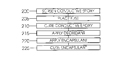
1:~ Figures 2 - ~ illustrate the preferred embodiments of the present invention. Therein a fuse
and assembly method are illustrated. The assembly method of the present invention
in(~ es in step 200 screen printing conductive epoxy ~20 onto fuse termination pads 350
and 370. Terrtlin~tion pads 350 and 370 are illustrated herein in the preferred
emho~iment as being metallic pads on a glass or ceramic substrate 305. However, one of
1~ ordinary skill will recognize that a variety of substrate materials and termination pad
21 94654
-- --S ~ . ,UE ~ C '~ MA.~'~ . .i~ 1CE:E~ ~.;C r;::jc .~ 1E '_5~ ~e~ ~ ' I 7. E~!C ~ ~licrl d ;l
compositions will be verv suited to the teachings of the present invention. ~urthermore.
~hile coIIductive epoxv 420 is sho~,vn, one of ordinaIy skill in the alt will recognize that
other filled or intrinsicallv conductive polvmers can similarly be used to fol~n the
intel-connection between f~lse liI~k 350 and terTninations 350 and 370.
The use of a conductive polvmer tvpe bond is novel in this application, since, in the prior
art, tennination pads 350 and 3 / 0 were depended upon to wick solder link 360, when link
360 Inelted. Polvrmer matelials. however, are notorious for not wetting well by solder. As
uill be explained further, the present invention does not depend upon the usual ~,vicking,
therebv allo~,ving the inventors the benefit of a less complex, lower temperature interconnect
- :! betweeIl link 360 and terminations 350 and 370.
In step 205, fuse link 3G0 is placed between termination pads 350 and 370, and pressed
iIltO the conductive epoxy 420. As best illustrated in figure 4, conduc~ive epoxy 420 will
then surround the ends of fuse link 360, thereby ensuring a reliable bond and electrical
interconnection .
i 5 Once fuse link 360 is placed, cond~lctive epoxy 420 is cured as shown in step 210. Typical
conductive epoxies cure at a temperature of 125 - 150 degrees Centigrade, which is well
below the melting point of tin-lead solders. Therefore, the curing process has no adverse
affect upon fuse link 360.
1'~
~1 94654
~.s --,c. .~E.r.~lOr or M~N., ~ .~Yi'~ '~L~L~ FUSE ~IC rt~E r'~ SE ~ESULrr:l~; ~E~ErttOM, Cti~ t ~ ~
Following the curing step 210, a deoxidant is applied in step 215. In the preferred
embodirllent, this deoxidant is one which remains liquid. such as SP-273 available from
ICester Solder located in Des Plaines, lllinois. Adipic acid mav be added at levels, for
ex-ample, of 15%. The particular deoxidant selected and the subsequent process is critical
for the successful performance of the fuse. The inventors have found that a tYpical cured
deoxidant will form a relativelY rigid straw-like structure around the fuse link, and the fuse
~ ill not open u p reliably during overload conditions. The use of a liquid deoxidant, which
is not subsequentlv cured, results in the forrnation of a chamber-like structure within
encapsulant 380. When link 360 melts, surface tension causes link 360 to divide into
sevelal more rounded pools of molten metal. So long as deoxidant 410 rernains fluid, link
360 will be allowed to pool. However, and this point is critical, the use of a deoxidant
which restricts link 360 from pooling or otherwise changing shape will result in failure of
the fuse to operate properly.
Once deoxidant 410 is applied, an encapsulant 380 is applied in step 220. The inventors
have discovered that an encapsulant used for encapsulating discrete components such as
resistors and ~p~itors after laser scribing is also an effective encapsulant for fuse link 360.
The preferred encapsulant is a solventless silicone conforrnal coating, part number 3-1744
available from Dow Corning located in l~ n~, Michigan. This particular encapsulant
is clear, which allows for visual inspection of the fuse. Additionally, there is no need for
elevated processing temperatures, thereby preserving the state of deoxidant ~10 and link
-~ . o ~1}-.i. r !~ iE ~E;~t î7tC .hSE ~.~ r r.YE r;~jE EE~ ?~EFR.M. ~ 2 1 9 4 ~ 5 4
360
The final step in the process, step 225, is the curing of encapsulant 380. As already noted,
this will preferahlv be done without the use of elevated temperatures, and with an
encapsulaIlt matelial that ~generates ~ miniIIlum of bvproducts during cure.
:- As a result of the simplified method of manufacture, step 220 of applying encapsulant 380
mav sometimes be a dual-function step. In those instances where additional components
3 30 and '335 share substl-ate 305 with fuse link 360, those components 330 and 335 may
simultaneousl~ be encapsulated. This is best illustrated in figure 3, wherein encapsulant
320 encapsulates device 330 and encapsulant 325 encapsulates device 335. As noted
hereinabo~e in reference to the prior art of figure 1, encapsulating additional laser kerfs and
culing the encapsulant required the t~vo additional steps 165 and 170.
As shown, electrical conductors 310, 315, 3~0 and 3~5 may be used to interconnect
valious electrical devices. While the foregoing details what is felt to be the preferred
embodi~nent of the invention, no material limitations to the scope of the claimed invention
5 is intended. Further, features and design alternatives that would be obvious to one of
ordinary skill in the art are considered to be incorporated herein. The scope of the
invention is set forth and particularly described in the claims hereinbelow.