Language selection

Search

Patent 2194813 Summary

Third-party information liability

Some of the information on this Web page has been provided by external sources. The Government of Canada is not responsible for the accuracy, reliability or currency of the information supplied by external sources. Users wishing to rely upon this information should consult directly with the source of the information. Content provided by external sources is not subject to official languages, privacy and accessibility requirements.

Claims and Abstract availability

Any discrepancies in the text and image of the Claims and Abstract are due to differing posting times. Text of the Claims and Abstract are posted:

  • At the time the application is open to public inspection;
  • At the time of issue of the patent (grant).
(12) Patent Application: (11) CA 2194813
(54) English Title: POWER PRESS
(54) French Title: PRESSE HYDRAULIQUE
Status: Deemed Abandoned and Beyond the Period of Reinstatement - Pending Response to Notice of Disregarded Communication
Bibliographic Data
(51) International Patent Classification (IPC):
  • D6F 71/04 (2006.01)
  • D6F 71/34 (2006.01)
  • D6F 71/36 (2006.01)
(72) Inventors :
  • LO, FRANCIS (Hong Kong, China)
(73) Owners :
  • SINGER COMPANY N.V. (THE)
(71) Applicants :
  • SINGER COMPANY N.V. (THE) (Netherlands Antilles)
(74) Agent: GOWLING WLG (CANADA) LLP
(74) Associate agent:
(45) Issued:
(22) Filed Date: 1997-01-10
(41) Open to Public Inspection: 1998-07-10
Availability of licence: N/A
Dedicated to the Public: N/A
(25) Language of filing: English

Patent Cooperation Treaty (PCT): No

(30) Application Priority Data: None

Abstracts

English Abstract


A power press having a press bed and lower ironing panel
secured to the press bed and including a generally horizontal upper face. A
press arm is pivotably mounted to the press bed. An upper press soleplate is
secured to the press arm and is movable with the press arm between closed
and open positions. A spraying device responsive to movement of the press
arm is further provided. A motor driven activator acts between the press bed
and the press arm to move the press arm and in turn the upper press
soleplate between the open and closed positions.


French Abstract

Presse hydraulique ayant une table de presse et un panneau inférieur de nivelage fixé à la table et comprenant une face supérieure généralement horizontale. Un bras de presse est monté sur la table de presse de manière à pouvoir pivoter. Une semelle de presse supérieure est fixée au bras de presse et peut se déplacer avec lui entre une position fermée et une position ouverte. Il y a aussi un dispositif de pulvérisation réagissant au mouvement du bras de presse. Un actionneur motorisé agit entre la table de presse et le bras de presse pour déplacer le bras de presse et la semelle de presse supérieure entre une position ouverte et une position fermée.

Claims

Note: Claims are shown in the official language in which they were submitted.

I CLAIM
1. A power press comprising:
a press bed;
a lower ironing panel secured to said press bed and having a generally
horizontal upper face;
a press arm pivotably mounted to said press bed;
an upper press soleplate secured to said press arm and movable with
said press arm between a closed position adjacent said lower ironing panel
and an open position away from said lower ironing panel;
a spraying device for spraying water at said upper surface of said lower
ironing panel; and
an actuator acting between said press bed and said press arm for
pivoting said press arm and said upper press soleplate between said open and
said closed positions.
2. A power press as claimed in claim 1 wherein said actuator includes;
a motor;
a first shaft rotatable by said motor;
a second shaft generally axially aligned with said first shaft;
a first coupling member connecting an outer end of said first shaft to a
first end of said second shaft to rotatably couple said first and second shafts
and allow relative axial movement between said first and second shafts;
a third shaft rotatably coupled at an inner end to a second end of said
second shaft by a swivel coupling to cause said second and third shafts to
rotate together while allowing angular misalignment therebetween;
said third shaft being threaded at least part way along its length;
said third shaft threadedly engaging a threaded boss pivotably mounted
to said press arm to cause said press arm to pivot relative to said press bed assaid third shaft is rotated;
an activating switch connected to said motor and movable between a
first position causing said motor to rotate in a first direction and a second
position causing said motor to rotate in a direction opposite to said first
direction;

-2-
a first limit switch for stopping said motor when said press arm and
said upper press soleplate are in said open position; and,
a second limit switch for stopping said motor when said press arm and
said upper press soleplate are in said closed position.
3. A power press as claimed in claim 2 further including a pressure sensor
responsive to pressure between said upper press soleplate and said lower
ironing panel for activating said first limit switch to stop said motor when a
predetermined force between said upper press soleplate and said lower
ironing panel is attained.
4. A power press as claimed in claim 3 wherein said pressure sensor
includes;
a disc extending about and secured to said second shaft;
a spring abutment secured to said press bed and extending substantially
about said second shaft;
a spring extending between said disc and said spring abutment, said
spring allowing said disc to move toward said spring abutment in response to
pressure between said upper press soleplate and said lower ironing panel;
said first limit switch acts against said disc to activate said first limit
switch when a force applied by said third shaft to said swing arm exceeds a
predetermined force exerted by said spring between said abutment and said
disc by a predetermined amount.
5. A power press as claimed in claim 4 further comprising a manually
operable safety release lever mounted to said press bed and acting against an
outer end of said third shaft to cause said press arm to move said upper press
soleplate away from said lower ironing panel against the force exerted by said
spring.
6. A power press as claimed in claim 1, 2, 3, 4 or 5 wherein said spraying
device is responsive to relative movement between said press arm and said
ironing press bed and includes;
a water reservoir;

-3-
a cylinder fluidly communicating with said water reservoir;
a piston slidably received in said cylinder;
a first one way valve mounted between said fluid reservoir and said
cylinder to permit fluid flow from said reservoir to said cylinder and inhibit
fluid flow from said cylinder into said reservoir;
a nozzle fluidly communicating with said cylinder, and directed at said
upper face of said lower ironing panel;
a second one way valve mounted between said nozzle and said
cylinder to permit fluid flow from said cylinder to said nozzle and inhibit
fluid flow from said nozzle to said cylinder; and,
a piston activator responsive to movement between said press arm and
said press bed to move said piston into said cylinder as said press arm begins
to move toward said closed position from said open position.
7. A power press as claimed in claim 6 wherein said piston activator
includes;
a base member to which said cylinder is mounted and having a sliding
fork mounted thereto for slidable movement therealong;
a piston rod extending between said piston and said sliding fork;
a spring mounted to act between said cylinder and said piston for
moving said piston out of said cylinder and in turn moving said piston rod
and said sliding fork away from said cylinder;
a cable for moving said sliding fork toward said cylinder to in turn
move said piston outwardly relative to said cylinder, said cable having a first
end secured to said sliding fork and a second end secured to an actuating arm;
said actuating arm being pivotably mounted to said press bed;
a rotating cam mounted to said actuating arm and rotatable therewith;
a swing cam secured to said press arm and pivotable therewith, and
wherein said swing cam presses against said rotating cam as said press arm is
initially moved toward said closed position and causes said rotating cam and
actuating arm to rotate and in turn to pull said cable to slide said sliding fork
toward said cylinder.

-4-
8. A power press as claimed in claim 7 wherein releasable engaging
means are provided between said piston rod and said sliding fork, said
releasable engaging means being movable between an engaged position in
which movement of said sliding fork toward said cylinder causes movement
of said piston rod and a disengaged position in which movement of said
sliding fork is not transmitted to said piston rod.

Description

Note: Descriptions are shown in the official language in which they were submitted.


21948i3
TlTLE POWER PRESS
INVENTOR: FRANCIS LO
FIFI n OF THE INVENTION
This invention relates to ironing presses.
BACICGROUND OF THE INVENTION
Ironing presses are an alternative to hand held irons for pressing
15 garments and other fabric items. Ironing presses generally include a fixed
lower ironing panel on which the garment is placed and a movable upper
press soleplate for applying pressure to the garment between the upper press
soleplate and the ironing panel.
Heretofore ironing presses were manually operated in that dosing of
20 the press and application of pressing force was manually applied to a handle
connected to the upper press soleplate. This required at least one hand to be
removed from the garment to close the ironing press and to apply pressure
to the garment.
An object of the present invention is to provide an ironing press
25 which is motor driven thereby enabling hands free operation.
A further object of the present invention is to provide a power
ironing press which applies a generally constant pressure regardless of
garment thickness to ensure good ironing effect.
A still further object of the present invention is to provide a power
30 press with a safety release me(~h~ni~m to allow separation of the upper press soleplate and the lower ironing panel to enable garment removal in the
event of power failure.
Yet a further object of the present invention is to provide a power
press with a hands-free water spraying system.

2191813
-2 -
SUMMARY OF THE INVENTION
A power press comprising:
a press bed;
a lower ironing panel secured to said press bed and having a generally
horizontal upper face;
a press arm pivotably mounted to said press bed;
an upper press soleplate secured to said press arm and movable with
said press arm between a closed position adjacent said lower ironing panel
and an open position away from said lower ironing panel;
a spraying device for spraying water at said upper surface of said lower
ironing panel; and
an actuator acting between said press bed and said press arm for
pivoting said press arm and said upper press soleplate between said open
and said closed positions.
DESCRI~IION OF DR~WINGS
The present invention is described in detail below with refert!nce to
the ~ccomranying drawings in which:
Figure 1 is a front elevation of a power press according to the present
invention;
Figure 2 is a front elevation of a power press according to the present
invention with a portion of the press bed cut away to illustrate the actuator;
Figure 3 is a bottom plan view of a press bed and part of a press arm
according to the present invention;
Figure 4 is a front elevation of a safety release lever according to the
present invention;
Figure 5 is a perspective view of a base of a s~iayi~lg device according
to the present invention;
Figure 6 is a top plan view of a spraying device according to the
present invention;
Figure 7 is a sectional view on line 7-7 of Figure 6;

219~813
-3 -
Figure 8 is an isometric view of a piston rod according to the present
invention;
Figure 9 is a perspective view of a sli&g fork according to the present
invention;
Figure 10 is a front elevation of a power press accordil~g to the present
invention showing details of the piston activator.
DESCRIPTION OF PREFERRED EMBODIMENTS
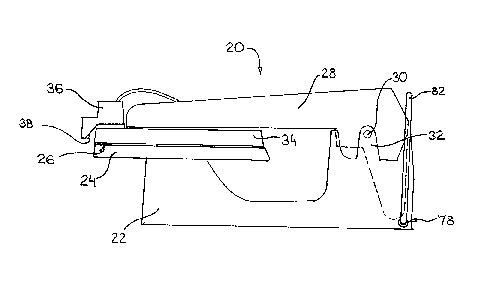
A power press is generally in~ te~3 by refer~llce 20 in figures 1, 2 and
10. The power press 20 includes a press bed 22 which acts as a base for the
power press 20. A lower ironing panel 24 is secured to the press bed and has
a generally horizontal upper face 26.
A press arm 28 is pivotably mounted to the press bed 22 by means of a
pivot pin 30 extending through the press arm 28 and journalled into
supports 32 e~ct~n~1ing upwardly on both sides of the press bed 22.
An upper press soleplate 34 is secured to the press arm 28 and
movable therewith between an open position shown in dashed outline in
Figure 2 and a closed position shown in solid outline in Figure 2. In the
closed position the upper press soleplate 34 is adjacent the lower ironing
panel 24. In the open position the upper press soleplate 34 is away from the
lower ironing panel 24 to allow garments to be removed from or placed on
the lower ironing panel 24.
A spraying device 36 is mounted adjacent an outer end of the upper
press soleplate 34. The spraying device 36 includes a nozzle 38 generally
directed at the lower ironing panel 24.

2194813
-4 -
An actuator indicated generally by reference 40 in Figure 2 acts
between the press bed 22 and the press arm 28 to pivot the press arm 28 and
upper press soleplate 34 between the open and closed positions.
The activator 40 includes a motor 42 connected to a first shaft 44
which is rotatable by the motor 42. A second shaft 46 is adjacent and
generally axially aligned with the first shaft 44. The second shaft 46 is
rotatably coupled to the first shaft 44 by a first coupling member 48. The firstcoupling member 48 includes some clearance to allow some axial
movement between the first shaft 44 and second shaft 46 in the direction of
arrows 50.
Any suitable coupling may be used for the first coupling member 48.
Illustrated in Figure 2 is a 'U' shaped slot in the end of the first shaft 44
which receives a generally rectangular tongue at the corresponding end of
the second shaft 46. Other suitable couplings such as cooperating splined
members or a socket which registers with a similarly shaped prong.
A third shaft 52 is rotatably coupled at an inner end 54 to a second end
of the second shaft by a swivel coupling 56 such as a 'U' joint. The swivel
coupling 56 allows the second shaft 46 to rotate the third shaft 56 despite
some angular misalignm~nt therebetween. The third shaft 52 is threaded at
least part way along its length as shown by reference 58.
The threaded part 58 of the third shaft 52 threadedly engages a
threaded boss 60 pivotably mounted to the press arm 28 to move the
threaded boss 60 along the third shaft 52 and in turn cause the press arm 28
to pivot relative to the press base 22 in the direction of the arrows 62 in
response to rotation of the third shaft 52.
The motor 42 is activated by depressing an activating switch 64 to
move the activating switch 64 to a first position to cause the motor 42 to
rotate in a first direction in which the press arm 28 and upper press plate 34

21g~813
-5-
move toward the closed position. A first limit switch 66 senses when the
press arm is in the closed position to stop rotation of the motor 42.
ReleAsing of the activating switch 64 allows the activating switch 64 to
5 move to a second position which causes the motor 42 to rotate in a direction
opposite the first direction thereby moving the press arm 28 and upper press
plate 34 to move toward the open position. A second limit switch 68
mounted between the press bed 22 and press arm 28 senses when the press
arm 28 and upper press soleplate 34 reach the open position to stop rotation
10 of the motor 42.
A pressure sensor generally indicated by refelel~ce 70 is provided to
activate the first limit switch 66 when a predetermined force has been
~t~ine-l between the upper press soleplate 34 and lower ironing panel 24. In
15 this manner the pressure exerted on a garment placed between the upper
press soleplate 24 and ironing panel 34 is determined by the pressure sensor
70 rather than by the thil~kness of the garment.
The pressure sensor 70 includes a disc 72 extending substantially
20 about and secured to the second shaft 46. The disc 72 is movable with the
second shaft 46. The pressure sensor 70 further includes a spring abutment
74 secured to the ironing press bed 22 and exten~ling subst~nti~lly about the
second shaft 46. The second shaft 46 is slidable through the spring abutment
74.
A spring 76 extends between the disc 72 and the spring abutment 74.
The spring 76 allows movement of the disc 72 toward the spring abutment
96 in response to pressure between the upper press soleplate 34 and the
lower ironing panel 24 which is tr~nsmitted along the second shaft 46. As
30 the disc 72 moves toward the spring abutment 74 it will eventually strike
the first limit switch 66 to activate the first limit switch 66 at a force
predetermined by the length and spring constant of the spring 76.

2194813
A manually operable safety lever 78 in Figures 1, 2, 3 and 4 is
mounted to the press bed 22 to enable the upper press soleplate to be moved
away from the lower ironing panel should the motor 42 fail to operate. The
safety lever 78 acts against an outer end 80 of the third shaft to press the
5 third shaft 52 and second shaft 46 toward the first shaft 44 against the force of
the spring 76. A handle 82 in Figures 2 and 4 is provided as part of the safety
lever 78 to assist in ~ct~l~hng the safety lever 78.
The spraying device 36 and its operation are further illustrated in
10 Figures 5 through 10. The spraying device 36 has a water reservoir 84 with a
filler orifice 86. A cylinder 88 fluidly communicates with the water reservoir
84 through an inlet 90. A first one way valve 92 is mounted between the
water reservoir 84 and the cylinder 88 to permit fluid (i.e. water) flow from
the water reservoir 84 into the cylinder 88 while inhibiting fluid flow from
15 the cylinder 88 back into the water reservoir 84.
A nozzle 90 fluidly communicates with the cylinder 88 through an
outlet 92. A second one way valve 94 is provided between the cylinder 88
and the nozzle 90 to permit fluid (i.e. water) flow from the cylinder 88 into
20 the nozzle 90 while inhibiting fluid (i.e. water or air) flow from the nozzle 90 back into the cylinder 88.
A piston 96 is slidably received by the cylinder 88. A piston activator
generally indicated by reference 98 is provided and is responsive to
25 movement between the press arm 28 and the press bed 22 to move the
piston 96 into the cylinder 88 as the press arm 28 begins to move from the
open position to the closed position.
The piston activator 98 includes a base member 100 to which the
30 cylinder 88 is mounted and which includes a sliding fork 102 mounted
thereto and slidable therealong. A piston rod 104 extends between the piston
96 and the sliding fork 102. A cable 106 analogous to a bicycle cable is
mounted in the base 100 and has a first end 108 secured to the sliding fork

- 21948~3
102 for causing the slit1ing fork 102 to move toward the cylinder 88. A second
opposite end 110 of the cable 106 opposite the first end 108 is secured to an
actuating arm 112 in Figure 10.
A spring 114 extends between an inner end of the cylinder 88 and the
piston 96 to urge the piston 96 out of the cylinder 88.
The actuating arm 112 is pivotably mounted to the press bed 22. A
rotating cam 116 in Figure 10 is mounted to the activating arm 112 and
rotatable therewith.
A swing cam 118 is secured to the press arm 28 and pivots therewith.
The swing cam 118 has a projection 120 which presses against a
corle~onding projection 122 on the rotating cam 116 as the press arm 28 is
initially moved from the open position toward the closed position. Pressure
of the swing cam 118 against the rotating cam 116 causes rotation of the
rotating cam 116 and in turn the actll~ting arm 112 to pull the cable 110 and
in turn slide the sli-ling fork 102 toward the cylinder 88.
Releasable engaging means are provided between the piston rod 104
and the sliding fork 102 such as prongs 120 in Figure 8 which extend radially
outwardly from opposite sides of the piston rod 104. The piston rod 104 is
rotatable about its axis between an engaged position in which the prongs 120
extend across sides 122 of the sli~ling fork 102 and a disengaged position in
which the prongs 120 line up with a slot 124 in the sli(ling fork 102. In the
engaged position, the prongs 120 abut against the sliding fork 102 to cause
the piston rod and in turn the piston 96 to move into the cylinder 88 in
response to movement of the sli~ling fork 102 toward the cylinder 88. In the
disengaged position the prongs 120 line up with the slot 124 to avoid being
acted upon by the slit1ing fork 102. In this manner S~ldyillg can be turned on
or off by the operator of the power press 20.

-
219 18~3
-8--
Rotation of the piston rod 104 about its axis between the engaged and
disengaged position may be effected by a handle 126 engaging a groove 128 in
the piston rod 104.
The above description is intended to be interpreted in an illustrative
rather than a restrictive sense. Variations to the structure described above
may be apparent to those skilled in such apparatus without departing from
the spirit and scope of the present invention as fl~fine-l by the claims set outbelow. It is intended that any variations within the spirit and scope of the
invention as ~l~fin~d by the claims be deemed to fall within the scope of this
patent.

Representative Drawing
A single figure which represents the drawing illustrating the invention.
Administrative Status

2024-08-01:As part of the Next Generation Patents (NGP) transition, the Canadian Patents Database (CPD) now contains a more detailed Event History, which replicates the Event Log of our new back-office solution.

Please note that "Inactive:" events refers to events no longer in use in our new back-office solution.

For a clearer understanding of the status of the application/patent presented on this page, the site Disclaimer , as well as the definitions for Patent , Event History , Maintenance Fee  and Payment History  should be consulted.

Event History

Description Date
Inactive: IPC from MCD 2006-03-12
Time Limit for Reversal Expired 2000-01-10
Application Not Reinstated by Deadline 2000-01-10
Inactive: Cover page published 1999-10-01
Deemed Abandoned - Failure to Respond to Maintenance Fee Notice 1999-01-11
Application Published (Open to Public Inspection) 1998-07-10

Abandonment History

Abandonment Date Reason Reinstatement Date
1999-01-11
Owners on Record

Note: Records showing the ownership history in alphabetical order.

Current Owners on Record
SINGER COMPANY N.V. (THE)
Past Owners on Record
FRANCIS LO
Past Owners that do not appear in the "Owners on Record" listing will appear in other documentation within the application.
Documents

To view selected files, please enter reCAPTCHA code :


To view images, click a link in the Document Description column (Temporarily unavailable). To download the documents, select one or more checkboxes in the first column and then click the "Download Selected in PDF format (Zip Archive)" or the "Download Selected as Single PDF" button.

List of published and non-published patent-specific documents on the CPD .

If you have any difficulty accessing content, you can call the Client Service Centre at 1-866-997-1936 or send them an e-mail at CIPO Client Service Centre.

({010=All Documents, 020=As Filed, 030=As Open to Public Inspection, 040=At Issuance, 050=Examination, 060=Incoming Correspondence, 070=Miscellaneous, 080=Outgoing Correspondence, 090=Payment})


Document
Description 
Date
(yyyy-mm-dd) 
Number of pages   Size of Image (KB) 
Drawings 1997-04-28 6 75
Representative drawing 1998-07-15 1 6
Description 1997-04-28 8 347
Abstract 1997-04-28 1 16
Claims 1997-04-28 4 164
Reminder of maintenance fee due 1998-09-13 1 115
Courtesy - Abandonment Letter (Maintenance Fee) 1999-02-07 1 184